logo elektroda
logo elektroda
X
logo elektroda

Converting shutters RF remote to WiFi with OpenBeken (sending button signals and reading feedback)

p.kaczmarek2 2580 2
ADVERTISEMENT
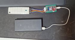
  • Roller blind remote connected to a WiFi module with wires and a power source.
    Many shutter controllers come with RF remotes but without WiFi connectivity, so they cannot be easily paired with Home Assistant. Luckily, it's always possible to simply inject remote button presses and intercept LED states with a simple WiFi module addon modification. Here I will show how to do it step by step in OpenBeken.

    Project was done by @DeDaMrAz, I'm just doing support and documentation.

    So, there are 5 shutters in total. They have one common remote.
    Remote has 5 buttons:
    - right/left (to select shutter)
    - top/down (to open/close)
    - middle (stop)
    Futhermore, the RF remote has also a simple LED feedback (five LEDs) which tells us which shutter we're currently controlling.
    The LEDs are either indicating room index (one of LEDs is lit), or a special "all rooms" mode (all LEDs are lit then).

    That's a total of 10 GPIOs - 5 outputs (to control buttons), and 5 inputs (to read LEDs).
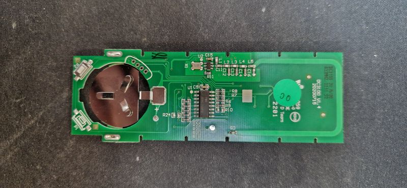
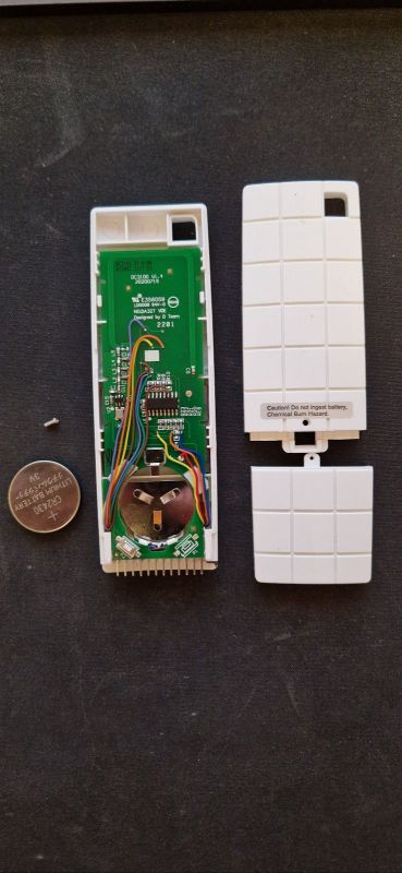
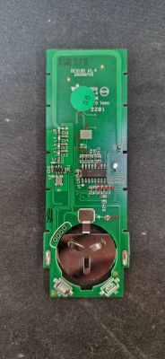
    Let's open the remote and look inside:
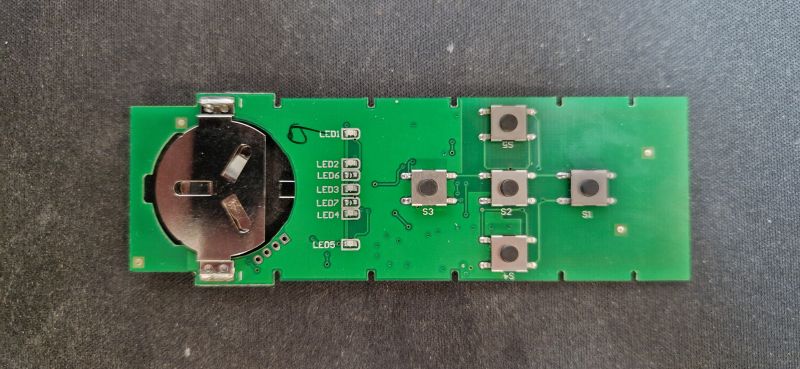
    Image of an electronic circuit board with buttons and a battery holder. Remote control circuit with visible battery compartment and electronic components.
    We can also overlay both images on single picture for more clarity:
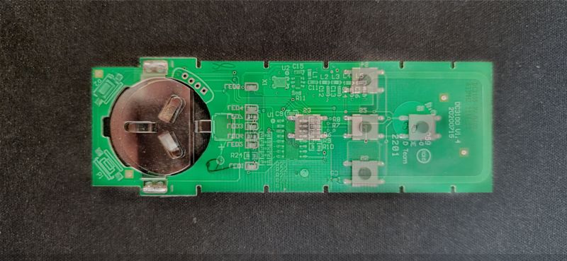
    Photo of remote control interior showing circuit board and battery slot.
    The next step is to figure out how to read LEDs and control buttons. We need to find points where we can solder wires:
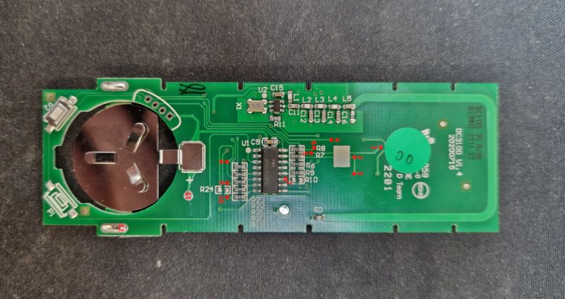
    RF remote control PCB with component markings.
    We didn't want to break the remote, or make it unusable without WiFi addon, so we decided to route out the signals to the male pin header:
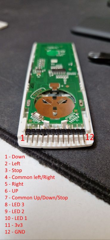
    Remote control circuit board with pins and button descriptions, side view.
    It's time for some soldering. First, the wires were soldered to the pins:
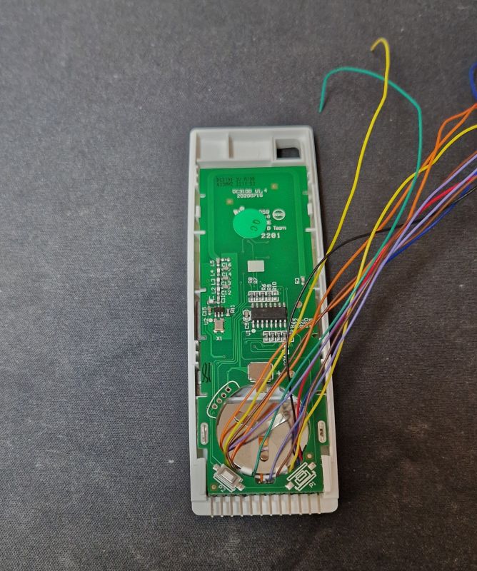
    Remote control for blinds with the case opened and attached wires.
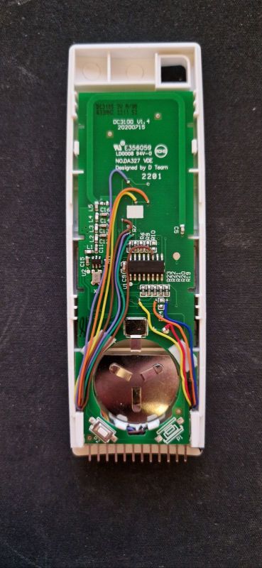
    Then, they were carefuly shorted and soldered to the appropriate pads:
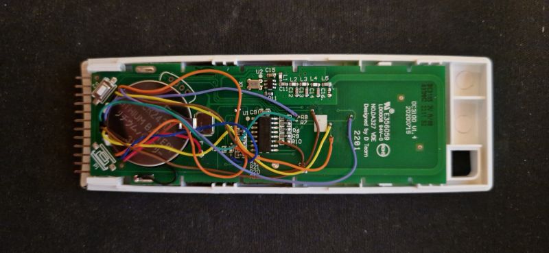
    Interior of an open remote with wires connected to the circuit board
    Opened RF remote with exposed PCB and wires soldered to pins. Interior view of RF remote with attached wires.
    Next step is the WiFi part. We can use any OBK device, but he had some NodeMCU mods at hand. @DeDaMrAz decided to use PC817's for buttons, however, in my opinion, that was not necessary - it depends on how the buttons are connected.
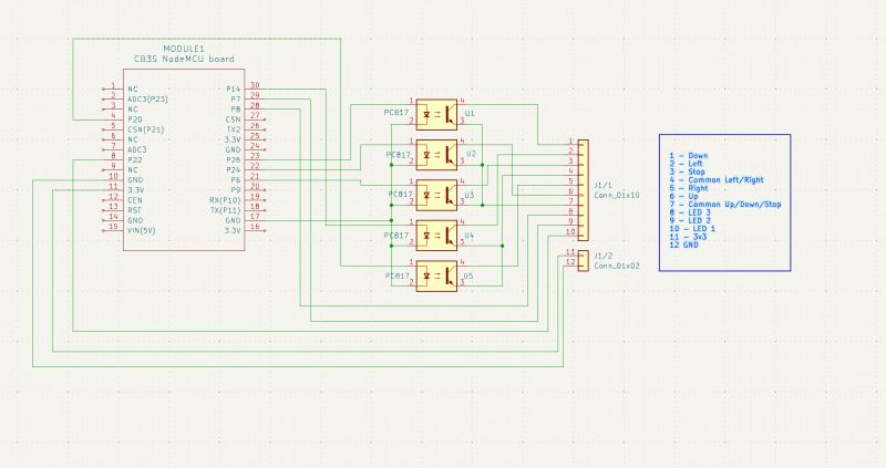
    Wiring diagram of NodeMCU module with PC817 circuit
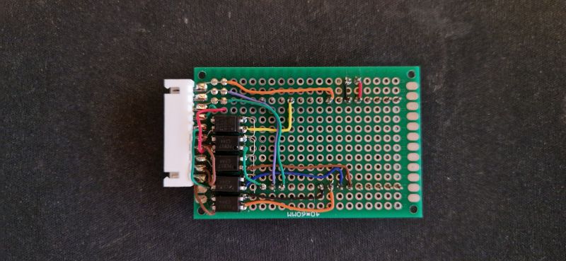
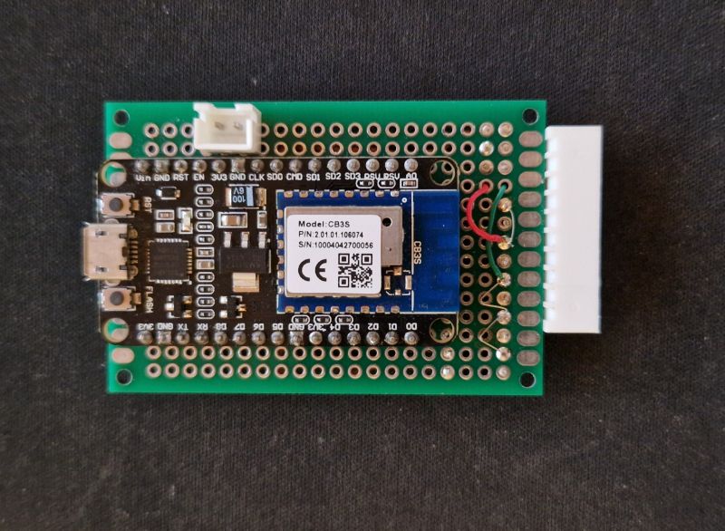
    So, here is the WiFi board:
    Prototype board with soldered wires and electronic components.
    WiFi module board with attached wires.
    The board can be seamlessly connected to the remote and the remote is still intact:
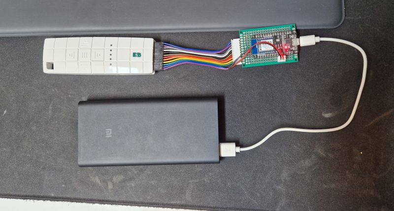
    Remote control with a connected WiFi board via colorful wires.
    Just please note that I'd recommend taking out the battery before connecting external supply.

    Now the hardware part is ready. It's easy to write a script for OpenBeken. No C coding required!
    GPIO config:
    Code: C / C++
    Log in, to see the code

    So, we start by enabling custom buttons:
    
    startDriver httpButtons
    

    Then we add change handlers to make 'button' channels go back to 0 after a short moment:
    
    addChangeHandler Channel1 == 1 addRepeatingEvent 0.2 1 setChannel 1 0
    addChangeHandler Channel2 == 1 addRepeatingEvent 0.2 1 setChannel 2 0
    addChangeHandler Channel3 == 1 addRepeatingEvent 0.2 1 setChannel 3 0
    addChangeHandler Channel4 == 1 addRepeatingEvent 0.2 1 setChannel 4 0
    addChangeHandler Channel5 == 1 addRepeatingEvent 0.2 1 setChannel 5 0
    

    The above code assumes that channels 1-5 have Rel roles (output pins).

    Then we handle reading from dInput pin channels to read LED states:
    
    //test for reading LED's from remote
    addChangeHandler Channel6 == 1 setButtonColor 6 BLUE
    addChangeHandler Channel6 == 0 setButtonColor 6 GREEN 
    addChangeHandler Channel7 == 1 setButtonColor 7 BLUE
    addChangeHandler Channel7 == 0 setButtonColor 7 GREEN
    addChangeHandler Channel8 == 1 setButtonColor 8 BLUE
    addChangeHandler Channel8 == 0 setButtonColor 8 GREEN
    

    They are just setting colors of buttons so we know which room we control.

    Finally, the buttons:
    
    //buttons
    setButtonLabel 1 "STOP"
    setChannelLabel 1 STOP
    setButtonColor 1 RED
    setButtonEnabled 1 1
    setButtonCommand 1 "setChannel 1 1"
    
    setButtonLabel 2 "UP"
    setChannelLabel 2 UP
    setButtonEnabled 2 1
    setButtonColor 2 ORANGE
    setButtonCommand 2 "setChannel 2 1"
    
    setButtonLabel 3 "DOWN"
    setChannelLabel 3 DOWN
    setButtonColor 3 ORANGE
    setButtonEnabled 3 1
    setButtonCommand 3 "setChannel 3 1"
    
    setButtonLabel 4 "LEFT"
    setChannelLabel 4 LEFT
    setButtonColor 4 GREEN
    setButtonEnabled 4 1
    setButtonCommand 4 "setChannel 4 1"
    
    setButtonLabel 5 "RIGHT"
    setChannelLabel 5 RIGHT
    setButtonColor 5 GREEN
    setButtonEnabled 5 1
    setButtonCommand 5 "setChannel 5 1"
    

    In the code above, the 5 buttons mimic the buttons of the remote.

    We also have extra buttons, which are used to signal which room is active:
    
    setButtonLabel 6 "OFFICE"
    setChannelLabel 6 OFFICE
    setButtonColor 6 GREEN
    setButtonEnabled 6 1
    //setButtonCommand 6 ""
    
    setButtonLabel 7 "ROOM 1"
    setChannelLabel 7 ROOM 1
    setButtonColor 7 GREEN
    setButtonEnabled 7 1
    
    setButtonLabel 8 "ROOM 2"
    setChannelLabel 8 ROOM 2
    setButtonColor 8 GREEN
    setButtonEnabled 8 1
    
    // NOTE: we didn't actually add here room 3, but it could be easily implemented if needed


    They don't have click events set, they just change colour when given room is active.

    Finally, we add extra button to remember last chosen room:

    
    setButtonLabel 9 "LAST SELECTION"
    setButtonColor 9 green
    setButtonEnabled 9 1


    Once a given LED lits up, we change the label:
    
    addChangeHandler Channel4 == 1 if $CH9==0 then NONE
    addChangeHandler Channel5 == 1 if $CH9==0 then NONE
    // last selection
    addChangeHandler Channel6 == 1 setButtonLabel 9 "OFFICE"
    addChangeHandler Channel7 == 1 setButtonLabel 9 "ROOM 1"
    addChangeHandler Channel8 == 1 setButtonLabel 9 "ROOM 2"
    addChangeHandler Channel9 != 0 setButtonLabel 9 "ALL"
    

    We also have the feature to track checking whether remote is connected to OBK:
    
    setButtonLabel 10 "NOT DETECTED"
    setChannelLabel 10 DETECTION
    setButtonColor 10 RED
    setButtonEnabled 10 1
    addChangeHandler Channel10 == 1 setButtonColor 10 GREEN
    addChangeHandler Channel10 == 0 setButtonColor 10 RED
    addChangeHandler Channel10 == 1 setButtonLabel 10 "DETECTED"
    addChangeHandler Channel10 == 0 setButtonLabel 10 "NOT DETECTED"
    

    We also need to handle an extra state, where all LEDs are lit, this indicates that all shutters will be controlled now:
    
    again:
    if $CH6==1&&$CH7==1&&$CH8==1 then "setChannel 9 1" else "setChannel 9 0"
    delay_s 1
    goto again
    

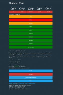
    And here is OBK panel (some buttons are not in English but it's just a demonstration):
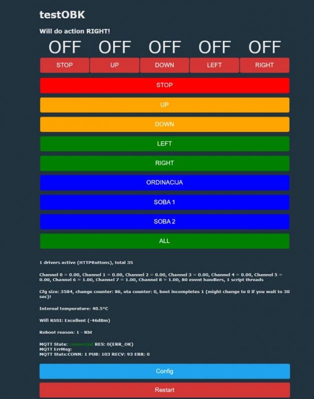
    OBK system user interface with various control buttons.
    It's important to keep in mind that first buttons are indeed clickable and they send events, while the futher buttons just mimic the state of LEDs.

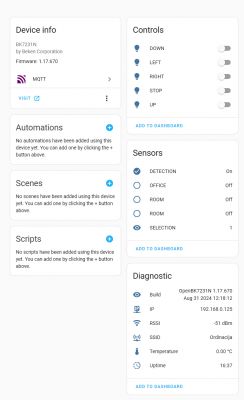
    We're also working on HA integration, but it's not fully read. Here's how automatic HASS Discovery sees this device:
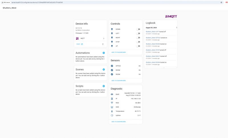
    Screenshot of the BK7231N device control panel.
    The following already gives us ability to control shutters from there, but there is much more to be improved soon.

    Futher improvements may include:
    - generic logic changes, better state tracking (if we detect any futher edge cases...)
    - better OBK page, maybe via rest interface:
    https://www.elektroda.com/rtvforum/topic3971355.html
    - better HA interface (probably via custom yaml)
    Of course, it should be also possible to control RF directly (with some RF receiver/sender modules), but that was not the scope of this topic.

    To, to sum up - this approach allows you to "hijack" any device remote and convert it to WiFi. It's not just limited to shutters, the same can be done for heating, cooling, air conditioning, PV monitoring, etc and so on systems.
    The project shown here is already functional but soon we may improve it even more and post extended version - stay tuned!

    Cool? Ranking DIY
    Helpful post? Buy me a coffee.
    About Author
    p.kaczmarek2
    Moderator Smart Home
    Offline 
    p.kaczmarek2 wrote 11917 posts with rating 9984, helped 572 times. Been with us since 2014 year.
  • ADVERTISEMENT
  • #2 21210961
    DeDaMrAz
    Level 19  
    A note on this project, this is still in very heavy development and I am adjusting things on the fly and still working on this but eventually goal is to add this to HA and make it 100% working. I will post updates if anybody is interested as I go.

    Many thanks to @p.kaczmarek2 for helping out with this!

    Added after 1 [hours] 44 [minutes]:

    I changed the design slightly to better handle LED's and added detection feature:

    PCB with electronic components and a battery holder.

    This will give me better reading as I am now reading before the LED's and so my signal has more consistency and no LED voltage bias in it.

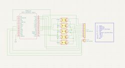
    Also changed schematics/wiring for detection feature:

    Circuit diagram with NodeMCU CB3S module and optoisolators.

    To be continued...
  • #3 21213596
    DeDaMrAz
    Level 19  
    This was rather interesting and great learning experience for me, I've completed what I had in mind and I'll share more details now. Remember this project was highly dependent on the device I am using but overall it was a great experience and in principal this method of "high jacking" should work on whatever device.

    This is the pin setup I ended up using.

      ],
      "pins": {
        "6": "Rel;3",
        "7": "dInput_NoPullUp;7",
        "8": "dInput_NoPullUp;8",
        "9": "dInput_n;10",
        "14": "Rel;4",
        "20": "Rel;5",
        "22": "dInput_NoPullUp;6",
        "24": "Rel;1",
        "26": "Rel;2"
      },


    Pin selection was a matter of playing around with a device and measuring the levels on it, I went with dInput_n for P9 as a detection pin for example as it was the best option for me and the logic in autoexec. For other inputs I utilized NoPullUp option as I tapped on the pullups of the remote and by doing so had much more consistent readings and no false readings in case all 5 LED's were on. Relay's are and obvious choice for outputs (button presses) as I am driving PC817 optocouplers with those pins.

    This would be my final autoexec with somewhat commented code:

    startDriver httpButtons
    
    //shortest time to pulse the channels
    addChangeHandler Channel1 == 1 addRepeatingEvent 0.2 1 setChannel 1 0
    addChangeHandler Channel2 == 1 addRepeatingEvent 0.2 1 setChannel 2 0
    addChangeHandler Channel3 == 1 addRepeatingEvent 0.2 1 setChannel 3 0
    addChangeHandler Channel4 == 1 addRepeatingEvent 0.2 1 setChannel 4 0
    addChangeHandler Channel5 == 1 addRepeatingEvent 0.2 1 setChannel 5 0
    
    //test for reading LED's from remote
    addChangeHandler Channel6 == 0 setButtonColor 6 BLUE
    addChangeHandler Channel6 == 1 setButtonColor 6 GREEN 
    addChangeHandler Channel7 == 0 setButtonColor 7 BLUE
    addChangeHandler Channel7 == 1 setButtonColor 7 GREEN
    addChangeHandler Channel8 == 0 setButtonColor 8 BLUE
    addChangeHandler Channel8 == 1 setButtonColor 8 GREEN
    
    //buttons setup
    
    setButtonLabel 1 "UP"
    setChannelLabel 1 UP
    setButtonColor 1 ORANGE
    setButtonEnabled 1 1
    setButtonCommand 1 "setChannel 1 1"
    
    setButtonLabel 2 "STOP"
    setChannelLabel 2 STOP
    setButtonColor 2 RED
    setButtonEnabled 2 1
    setButtonCommand 2 "setChannel 2 1"
    
    setButtonLabel 3 "DOWN"
    setChannelLabel 3 DOWN
    setButtonColor 3 ORANGE
    setButtonEnabled 3 1
    setButtonCommand 3 "setChannel 3 1"
    
    setButtonLabel 4 "LEFT"
    setChannelLabel 4 LEFT
    setButtonColor 4 GREEN
    setButtonEnabled 4 1
    setButtonCommand 4 "setChannel 4 1"
    
    setButtonLabel 5 "RIGHT"
    setChannelLabel 5 RIGHT
    setButtonColor 5 GREEN
    setButtonEnabled 5 1
    setButtonCommand 5 "setChannel 5 1"
    
    setButtonLabel 6 "OFFICE"
    setChannelLabel 6 OFFICE
    setButtonColor 6 GREEN
    setButtonEnabled 6 1
    
    
    setButtonLabel 7 "ROOM 1"
    setChannelLabel 7 ROOM 1
    setButtonColor 7 GREEN
    setButtonEnabled 7 1
    
    
    setButtonLabel 8 "ROOM 2"
    setChannelLabel 8 ROOM 2
    setButtonColor 8 GREEN
    setButtonEnabled 8 1
    
    //various aliases for detection and led readings
    alias NONE setButtonLabel 9 "NONE"
    alias DETECTED backlog setButtonLabel 10 "DETECTED"; setButtonColor 10 GREEN
    alias NOT_DETECTED backlog setButtonLabel 10 "NOT DETECTED"; setButtonColor 10 RED
    alias ZERO setChannel 11 0
    
    setButtonLabel 9 "LAST SELECTION"
    setButtonColor 9 GREEN
    setButtonEnabled 9 1
    addChangeHandler Channel4 == 1  if $CH9==0 then NONE
    addChangeHandler Channel5 == 1  if $CH9==0 then NONE
    addChangeHandler Channel6 == 1 setButtonLabel 9 "OFFICE"
    addChangeHandler Channel7 == 1 setButtonLabel 9 "ROOM 1"
    addChangeHandler Channel8 == 1 setButtonLabel 9 "ROOM 2"
    addChangeHandler Channel9 != 1 setButtonLabel 9 "ALL"
    
    setButtonLabel 10 "NOT DETECTED"
    setChannelLabel 10 DETECTION
    setButtonColor 10 RED
    setButtonEnabled 10 1
    
    
    //reporting the state to HA
    addChangeHandler Channel6 == 0 setChannel 11 1
    addChangeHandler Channel7 == 0 setChannel 11 2
    addChangeHandler Channel8 == 0 setChannel 11 3
    addChangeHandler Channel9 == 1 setChannel 11 4
    addChangeHandler Channel4 == 1  if $CH9==0 then ZERO
    addChangeHandler Channel5 == 1  if $CH9==0 then ZERO
    setChannelLabel 11 SELECTION
    //publishChannel 11
    
    //loop for reading states of led's and detection
    again:
    if $CH6==0&&$CH7==0&&$CH8==0 then "setChannel 9 1" else "setChannel 9 0" 
    if $CH10==0 then DETECTED else NOT_DETECTED
    delay_s 2
    goto again


    One thing to mention is that I set CH11 to be ReadOnly so I can publish the value to HA and convert it to meaningful reading with some customization in configuraion.yaml file.

    sensor:
      - platform: template
        sensors:
          location_status:
            friendly_name: "Last used"
            value_template: >
              {% set value = states('sensor.shutters_west_selection') %}
              {% if value == '0' %}
                NONE
              {% elif value == '1' %}
                OFFICE
              {% elif value == '2' %}
                ROOM 1
              {% elif value == '3' %}
                ROOM 2
              {% elif value == '4' %}
                ALL
              {% else %}
                UNKNOWN
              {% endif %}


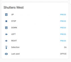
    I created an template "last used" that I can then use against CH11 reading and convert that into text instead of numbers.

    Device in HA as discovered:

    Control panel for the BK7231N device with various options.

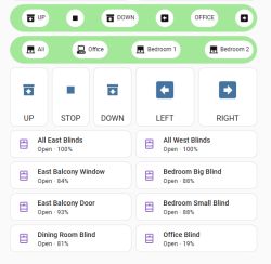
    Custom card in HA dashboard with that template used:

    User interface controlling shutters with buttons for directions and information on detection and last used option.

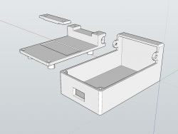
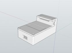
    In the end I decided to create a custom 3D printed case for it and went over several design iterations to confirm dimensions and tolerances, I believe it took me 8 or 9 revisions. I ended up with this for my final design.

    3D enclosure design consisting of two parts in SketchUp Prototype device enclosure created in SketchUp.

    I did that in SketchUp (as I am used to it) and attached are the files both original and exported STL.

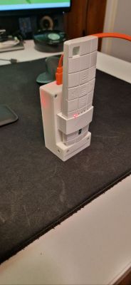
    And finally this is what the device looks like along with OBK home page:

    Electronic device mounted in a white 3D-printed case
    Control panel for Shutters_West with control buttons.

    Everything works as intended together with HA integration and control.
ADVERTISEMENT