logo elektroda
logo elektroda
X
logo elektroda

Teardown and Reflashing of Tuya Smart Socket EU20A with LN882HKI Chip Analysis

bogdanelhh 6843 57
ADVERTISEMENT
  • #31 21597976
    p.kaczmarek2
    Moderator Smart Home
    Well, with some extra caution the basic testing can be done still with 230V. Just carefully probe where the low voltage should be, usually the input and the output of AMS1117-3.3V, or, in the case of the board from the first photo, VDD and GND pins.

    Of course, detach flash tool first. Otherwise you'd short mains to your PC and damage it.
    Helpful post? Buy me a coffee.
  • ADVERTISEMENT
  • #32 21599283
    blacksun2
    Level 8  
    >>21597920
    The socket in question doesn't make a sound anymore. The chip doesn't even activate when I use the contact pins.
    The same thing happens with the 19V power supply.

    I bought a whole collection of these smart sockets on AliExpress.
    There was one among them that also had a Lightning LN882HK1.
    It finally worked with that one.

    Is it still current that with an LN882H chip you have to set "Powersave 1" via autoexec.bat?
    And is it still current that you can't do this via "Startup Command Text," but only via autoexec.bat?

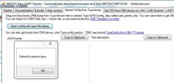
    I created a backup with LN882H_Flash_Dumper.py. How can you extract the Tuya OBK information from "flash.bin"? The Elektroda Flasher tool for Beken can't handle flash.bin.

    Teardown and Reflashing of Tuya Smart Socket EU20A with LN882HKI Chip Analysis

    How can I get for example the PIN-config?
  • #33 21599335
    divadiow
    Level 35  
    blacksun2 wrote:
    How can you extract the Tuya OBK information from "flash.bin"? The Elektroda Flasher tool for Beken can't handle flash.bin.


    your dump is from a device with schema e1k70tx4 which we've seen before. Is your device template not this?:

    Code: JSON
    Log in, to see the code


    Easy Flasher cannot extract every config from dump file.

    As far as I know, this is still correct:

    Code: Text
    Log in, to see the code
  • #34 21599346
    blacksun2
    Level 8  
    divadiow wrote:

    Is your device template not this?:
    Code: JSON
    Log in, to see the code


    Easy Flasher cannot extract every config from dump file.


    ah, ok, I didn't know that. I thought Easy Flasher can extract any Tuya Templates from any dump of Tuya-devices.
    The PIN-Setting worked for the device, but it was pure coincidence that I guessed correctly.
    I ordered 10 different smart plugs from AliExpress. They were all from different retailers. The packaging and labeling don't usually reveal much. The only thing you can figure out is which original app is required, whether Tuya or eWeLink.

    would you be so kind and have a look at this dump file:
    https://www.elektroda.com/rtvforum/topic4128200.html#21599325
    It is a bk7231N and the Easy Flasher cannot extract config too.

    Big thanks.
  • ADVERTISEMENT
  • #35 21602831
    blacksun2
    Level 8  
    >>21599346
    Is there a known problem with these smart Plugs with LN882H Chip and WiFi?

    Yesterday, I installed an OBK update on my plug. Since then, I've been having the problem that the plug no longer connects to the Wi-Fi network.
    At first, I thought it was a problem with the newer version of OBK and I reinstalled 1.18.131 via tx and rx and configured it newly. But the problem still persists.
    I have to plug and unplug the outlet at least 10 times before it reconnects to the Wi-Fi network. Often, but not always, the connection works as long as you don't unplug the outlet again.
  • #36 21602843
    divadiow
    Level 35  
    I do keep hearing about such an issue. Which version did you upgrade from that worked ok?
  • #37 21602868
    blacksun2
    Level 8  
    >>21602843

    Before the update, the device was running version 1.18.131. Then I installed the OTA.bin file for 1.18.133 (via -> config -> Wi-Fi OTA, not via web app). After that, the device stopped coming online, and the button stopped responding.
    I thought something had gone wrong with the update, so I installed 1.18.133 serially, using the bin file without OTA in the filename.
    I was wondering why the socket with the OBK, with its factory settings, wasn't sending out a Wi-Fi AP. I disconnected and reconnected the power several times. Eventually, OBK started, and I was able to integrate the socket into my Wi-Fi network and reconfigure it. Then I noticed again that the connection was lost during the configuration.
    Since I suspected a problem with 1.18.133, I was annoyed and reinstalled 1.18.131 via serial, thinking everything would be fine again. Unfortunately, that's not the case. Even with the older version, it takes countless unplugging and plugging ins before the outlet connects to the Wi-Fi. It could be a coincidence, but with 1.18.131, the connection at least doesn't drop while you're working on the web interface.

    I wouldn't swear that the outlet worked perfectly with 1.18.131 before. It could also have been a coincidence that I didn't notice the problems.

    There's also a minor flaw in the web app for OTA. The web app expects an rbl file as an update file. For LN882H, however, there are only bin files.

    What I can say, however, is that since I reinstalled and configured the outlet, the button is working again, which wasn't the case after the online update. The button works even when there's no Wi-Fi connection. This indicates that OBK is at least running.
  • #38 21607646
    Drakarah
    Level 5  
    I've made a dump of my plug, which seems to be the same or at least very similar with the same chip. I've checked the SHA256 with the firmware that was already posted earlier in the thread and they are different.

    Flashing OpenBeken worked fine as well with the wiring instructions posted earlier in the post
  • #39 21614453
    olivluca
    Level 7  
    I'm trying to get this device working with esphome (sorry folks) and I cannot get any data from the BL0937.
    Are you sure it is working with openbeken?
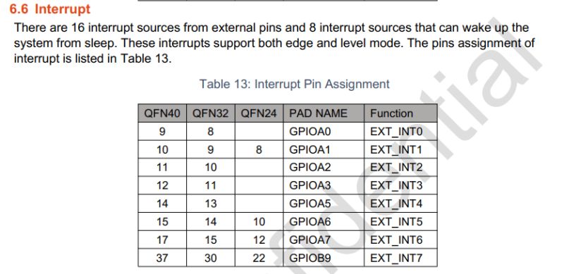
    The BL0937 driver uses interrupts to count the CF and CF1 pulses, but according to the datasheet only bank A can use interrupts while CF and CF1 are in bank B.

    Edit: I'd try openbeken myself but I broke the A9 pad while soldering, so I cannot flash it via serial.
  • #40 21614460
    divadiow
    Level 35  
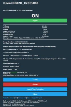
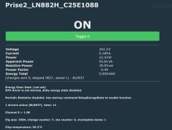
    I have this running currently.
    gif
    Screenshot of OpenLN882H device dashboard displaying sensor and status data

    I can't remember if I calibrated it and I'm not sure if the reading behaviour indicates something is off, but it looks like it's working

    Added after 10 [minutes]:

    olivluca wrote:
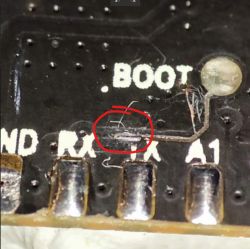
    but I broke the A9 pad while soldering, so I cannot flash it via serial.
    could scrape some of the coating off the leading trace? like: https://www.elektroda.com/rtvforum/topic4028087-30.html#20966104

    Close-up of PCB showing exposed trace between RX and TX pins, marked with a red circle
  • #41 21614489
    p.kaczmarek2
    Moderator Smart Home
    @olivluca I would advice against flashing not tested solutions, especially when you can't go back easily when pads break.
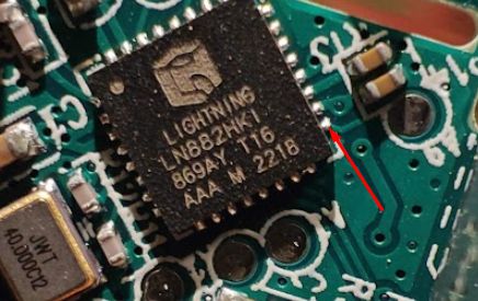
    Do you have module version, or like from first post?
    Close-up of LNB821HK1 chip on PCB with a red arrow pointing at a circuit trace
    Helpful post? Buy me a coffee.
  • ADVERTISEMENT
  • #42 21614514
    olivluca
    Level 7  
    divadiow wrote:

    I can't remember if I calibrated it and I'm not sure if the reading behaviour indicates something is off, but it looks like it's working


    So the datasheet is wrong then?

    divadiow wrote:

    could scrape some of the coating off the leading trace?


    It's actually like the picture posted below and I'm quite bad with a soldering iron, I'll see if I can get help from a colleague with better equipment and abilities :-D

    p.kaczmarek2 wrote:
    @olivluca I would advise against flashing not tested solutions, especially when you can't go back easily when pads break.
    Do you have module version, or like from first post?
    Close-up of LNB821HK1 chip on PCB with a red arrow pointing at a circuit trace


    Yes, it's like that, but if nobody tests untested solutions they'll never become tested ;-)
    In any case I broke the pad while re-soldering the cable to flash openbeken....
  • #43 21614541
    divadiow
    Level 35  
    olivluca wrote:
    So the datasheet is wrong then?


    unsure. I see this

    Interrupt pin assignment table showing PAD names GPIOA0–GPIOB9 and EXT_INT functions

    GPIO description stating 20 ports split into GPIOA and GPIOB, with interrupt mode for Group A

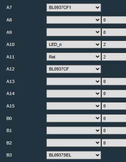
    my assignments:
    Screenshot of port configuration A7–B3 with dropdown selections

    Added after 11 [minutes]:

    are external interrupts a different thing? I don't know enough..
  • #44 21614566
    olivluca
    Level 7  
    In your configuration both CF and CF1 are in bank A, in this device (according to the json in the first page which I copied here) are in bank B, it's a different device.

    
    {
      "vendor": "Tuya",
      "bDetailed": "0",
      "name": "ISPTEC Tuya Smart Socket EU16/20A Wifi Smart Plug With Power Monitoring",
      "model": "EU20A",
      "chip": "LN882H",
      "board": "TODO",
      "flags": "1024",
      "keywords": [
        "LN882HKI",
        "BL0937"
      ],
      "pins": {
        "6": "LED_n;0",
        "7": "Btn;0",
        "19": "Rel;0",
        "20": "BL0937CF;0",
        "21": "BL0937CF1;0",
        "22": "BL0937SEL;0"
      },
      "command": "",
      "image": "https://obrazki.elektroda.pl/YOUR_IMAGE.jpg",
      "wiki": "https://www.elektroda.com/rtvforum/topic4091325.html"
    }


    Added after 3 [hours] 59 [minutes]:

    It turns out that, in spite of the documentation, even GPIOs of bank B can generate interrupts. I fixed the problem in libretiny with this modification.
    I found the missing calls by looking at the BL0937 driver in OpenBeken, so thank you.
  • #45 21619377
    brazoayeye
    Level 4  
    Oh, I probably cooked my plug.
    I welded as described and all worked well till I grounded A9. When I did it usb device had an overcurrent, the cpu became very hot and stopped blinking the led.

    Maybe welding I also grounded the near capacitor, or is it because I grounded A9 with the 3v3 connected?
  • #46 21619424
    olivluca
    Level 7  
    brazoayeye wrote:
    Maybe welding I also grounded the near capacitor, or is it because I grounded A9 with the 3v3 connected?


    It depends: if you shorted the side of the capacitor near the chip then, yes, you shorted 3.3V to ground. If you shorted the other side it's already ground. In fact one of the pins (in theory) is 1.1V output from the chip, so if you shorted it to ground you probably destroyed the chip.
  • #47 21640103
    earurelay
    Level 5  
    Hi guys,

    Did convert two EU20A plugs to openBk and it worked flawlessly!

    Thanks!

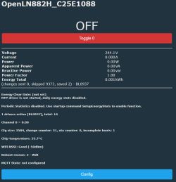
    Screenshot of openBk interface for EU20A socket showing energy measurements

    By the way, I ordered one EU20A and one EU16A. Inside they are strictly identical. Good to know :)
  • #49 21640155
    earurelay
    Level 5  
    >>21640106 Yes, 20A for each relay. Same model and reference also.

    I found absolutely no difference (passive and active components are exactly identical on both PCB). I even checked each resistor, diode, ... The same ! :)
  • ADVERTISEMENT
  • #50 21640189
    p.kaczmarek2
    Moderator Smart Home
    It reminds me of what I've seen when testing LD25/LD35 Chinese dummy loads.
    https://www.elektroda.com/rtvforum/topic3494513.html#17412016
    So... it seems that in this case it's better to buy 16A version? What were the prices?
    Helpful post? Buy me a coffee.
  • #51 21645645
    derKeks
    Level 3  
    Thank you @bogdanelhh for being the pioneer. Your guide helped me a lot and I could successfully flash one of my smart plugs. Different brand/name but the same circuit.

    @divadiow @max4elektroda @p.kaczmarek2 I don't know whether I should start a new thread or just post here because I have a "problem" with the same unit shown in this thread:
    I flashed and set up Wi-Fi/pins config. The web interface shows real-time values. So far so good. (side note: I did not integrate it in HA yet). Currently I am investigating the AP mode. I can go into AP mode via webapp command but I cannot enter AP mode by 5 times power cycle nor long pressing. When I enter the AP mode via webapp command the LED on the smart plug is not blinking! It does not show that it is in AP mode. I can see on my smartphone that the AP is created but the LED is not blinking.

    Maybe I don't need the feature to see whether AP mode is on or off by the LED but the feature to enter AP mode is useful in some circumstances. Especially if you have to set them up and somehow they don't connect to Wi-Fi and you cannot enter AP mode to rescue it.

    Do you know why my smart plug does not enter the AP by pressing the hardwired button? Or why does it not show the AP mode by a blinking LED?

    Side note: I used an old Raspberry Pi 3 for flashing. I think many people have an old Pi somewhere lying around. Good alternative instead of buying an UART adapter ^^
  • #52 21645677
    max4elektroda
    Level 21  
    Regarding the problem of safe mode failing (5 unsuccessful boots) I can only imagine that not all reboots where counted because the online time was to long (and it was interpreted as successful) or the reboot was so fast, it was not yet seen as start.
    The LED will follow the settings for the pin in the config page. Maybe there's an issue? Will it change color after plug connected to your WiFi?
    To be honest I'm not sure if pressing button for long is configured to enter AP mode.
  • #53 21645794
    p.kaczmarek2
    Moderator Smart Home
    Maybe there are capacitors on the board and you do not wait long enough for them to discharge.

    We don't support "AP mode by long button press", because when I tested Tasmota in the past, this feature was breaking my devices while testing pins - it happened several times, I remember setting wrong button pin and getting fake "long press" tasmota events which then were resetting my Tasmota device to factory settings. Very annoying.
    Helpful post? Buy me a coffee.
  • #54 21646024
    derKeks
    Level 3  
    Okay, I have troubles understanding what to do to bring a flashed device into AP mode by using the physical button.

    When I have an unflashed Tuya device I only get into AP mode by long pressing. Somehow 5 power cycles do not work anymore ^^ or I don't know what that means.

    But the flashed device is not able to get into AP mode by the physical button.


    Maybe my timing is wrong in the 5 power cycles. Can you explain or show me a video about this?


    Tasmota interface showing power and device status from BL0937
  • #55 21646083
    max4elektroda
    Level 21  
    There is no function, like in Tuya, to enable the AP mode by physical button.

    So if device is accessable, you should use the GUI to enabe AP

    If device is unaccessable, the SAFE MODE can be accessed by fast reboots 5 times in a row (it needs to be restarted during the first 5 seconds)
    One easy way is to cascade two plugs, so you can power/power off the second one fast with the first ones button, without physicaly unplugging it.
  • #56 21646094
    derKeks
    Level 3  
    Thank you so much. It works as you described! Now I understand the difference between handling a Tuya device and an Openbkn device. My problem was that I used the physical button instead of unplugging the device or toggling the power supply.

    My problem is solved. :)
    (Unfortunately I cannot vote your post as helpful, I am too new :D )
  • #57 21646192
    p.kaczmarek2
    Moderator Smart Home
    Ah I see... you've assumed that "turn off and on the power" means toggling the relay? No, that refers to power of the whole device - so WiFi module can reboot. Maybe we should clarify that in our docs...
    Helpful post? Buy me a coffee.
  • #58 21646204
    derKeks
    Level 3  
    >>21646192 Yeah, the docs were not clear or obvious. I read different threads with multiple guide links and how-tos. many times "5 times power cycle" were mentioned to enter AP mode. I did not realize that AP mode equals safe mode and is different to the stock device. I did not know where to find or read generic documentation/instructions in the beginning. just now i stumbled upon this link:
    https://github.com/openshwprojects/OpenBK7231T_App/tree/main/docs


    If I would have found the previous link earlier I would have stumbled over the safe mode. So I think this fault is on my side.

    but to answer your question: yes, I think the section "safe mode" is not clear enough. I think it would be a good idea to add the information that you must not use the device on/off switch. either unplugging or using your method with a switch in series to act as unplugger.

    I am so glad about this whole project. I was scared that my HA will be inconsistent with the shitty tuya integration. Especially when I saw that Tuya is not compatible anymore. luckily the LN chip is still compatible. so glad! thank you very much for your contribution

    PS: I did not use any instructions from the docs :D flashing.md does not contain my way. I guess there are many ways to achieve the same goal. I used https://github.com/mandl/LN882Loader on my Raspberry Pi.

Topic summary

The discussion focuses on the teardown and reflashing process of the Tuya Smart Socket EU20A, which uses the LN882HKI chip and supports power monitoring via the Smart Life app with Google Assistant and Alexa integration. The original poster successfully soldered wires to the chip's UART pins (notably A9 to GND for download mode) and flashed the device using an external 3.3V power supply and a CH340 USB-to-serial adapter. Key UART pins identified include RX0/TX0 on A3/A2 (pins 11 and 10) and RX1/TX1 on B8/B9. The reflashing process involves entering download mode by pulling A9 to ground, with LED behavior indicating mode status. Users reported challenges with unstable web configuration interfaces and long firmware dump times (~40 minutes). A configuration template was shared, mapping pins for LED, button, relay, and BL0937 power metering chip signals. Calibration of the BL0937 chip is necessary for accurate power measurement, achievable via the device's web app tools. Backup of original firmware before flashing is recommended but often difficult due to instability. Alternative flashing methods and device variants with different chips (e.g., T34, BK7231N) were noted, with OpenBeken firmware supporting multiple chipsets. Practical advice includes using short cables, lowering serial baud rates (e.g., 115200 or 921000), and ensuring solid ground connections to improve flashing reliability. The community provided links to related resources, firmware repositories, and configuration guides to assist in reflashing and configuring the device for custom use cases such as solar panel energy monitoring.
Summary generated by the language model.
ADVERTISEMENT