logo elektroda
logo elektroda
X
logo elektroda

Another ELIVCO LSPA9: BSD342-2110 PCB with [LN882H] and [BL0937]

max4elektroda 4890 31

TL;DR

  • Elvico LSPA9 smart plug uses a BSD342-2110 PCB with a WL2S-labeled LN882H module, BL0937 energy metering, and a relay marked 16A/20A.
  • The case opens by pressing the lightly glued halves from the sides, then the firmware can be flashed through Rx0/Tx0 on the main PCB.
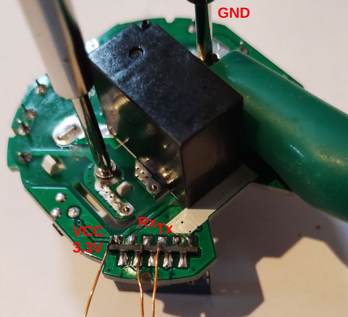
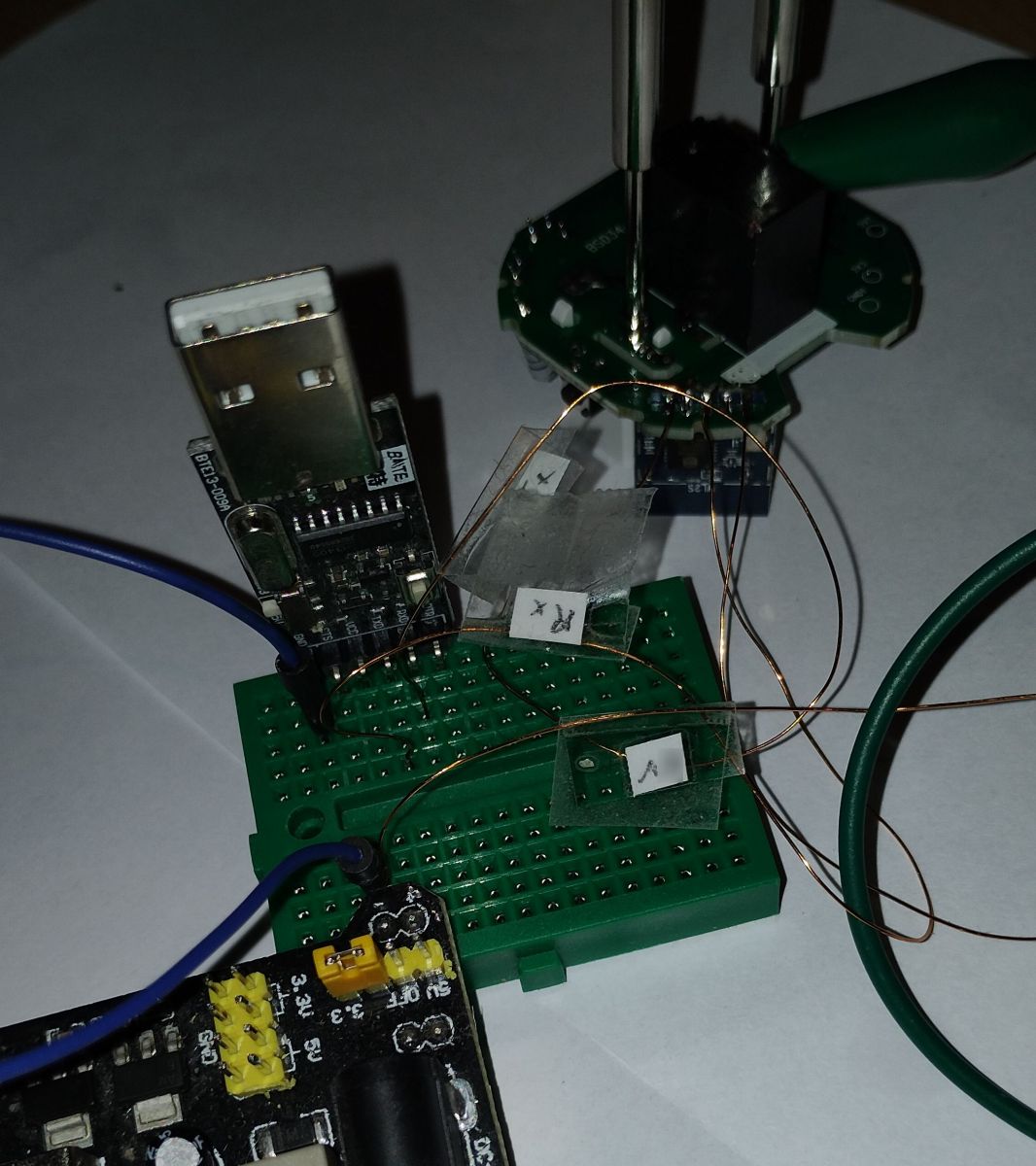
  • Only three wires are needed for flashing: 3.3 V VCC, RX, and TX, while the power pin opposite the LN882H can serve as GND.
  • A9 must be briefly shorted to GND after power-up, and flashing worked reliably at 115200 rather than 200000.
  • The included OpenBeken template maps GPIOs for LED, button, relay, Wi-Fi LED, BL0937 CF/CF1, and BL0937SEL.
Generated by the language model.
ADVERTISEMENT
📢 Listen (AI):
  • This plug was already mentioned here
    and here is the very useful page about the LN882H.

    The inside is exactly the same PCB as mentioned here with another socket case and a different relay.
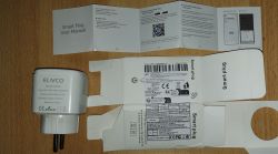
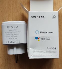
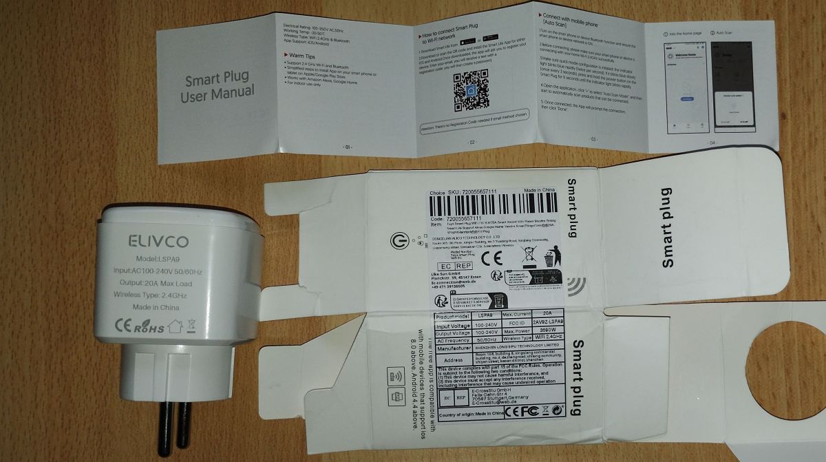
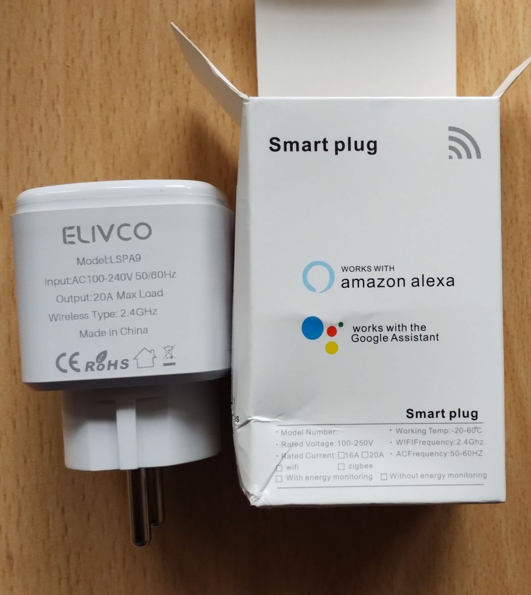
    ELIVCO LSPA9 smart plug with user manual and packaging ELIVCO smart plug with packaging.

    So, why another post? I think I might give some useful information here, so I hope it's o.k.
    (If there should not be a new post, for the same device, please move it into one of the other posts)

    First about opening the device:

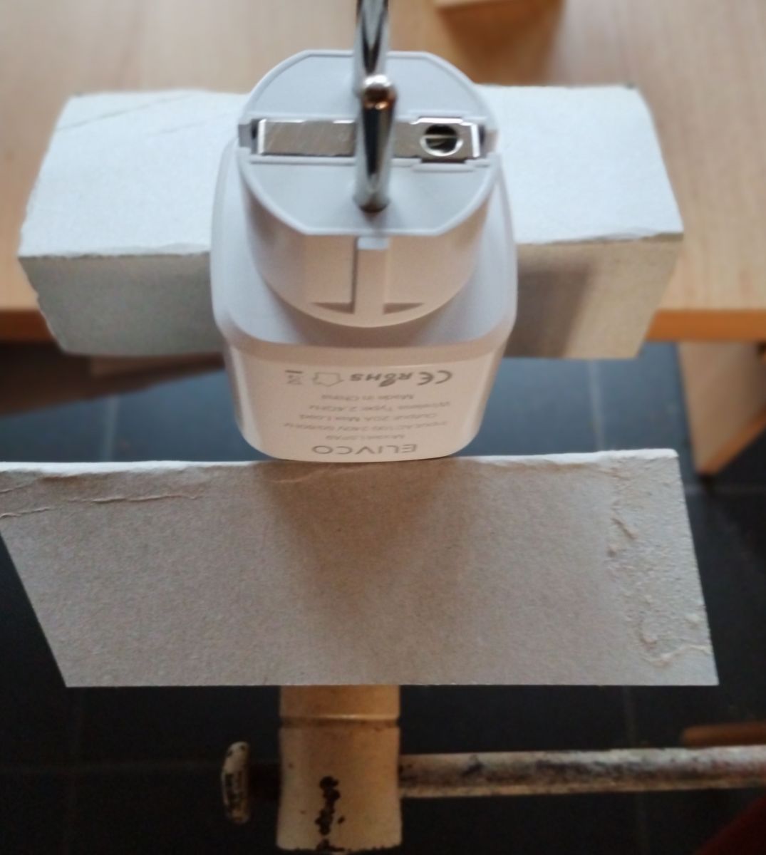
    The upper and lower part are lightly glued together and the pressure on the sides should break it open.
    I opened the case with help of a vice, so you can apply pressure on the whole sides.
    Just use some thick paper or cardboard to avoid marks on the case.
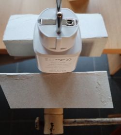
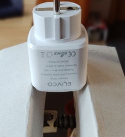
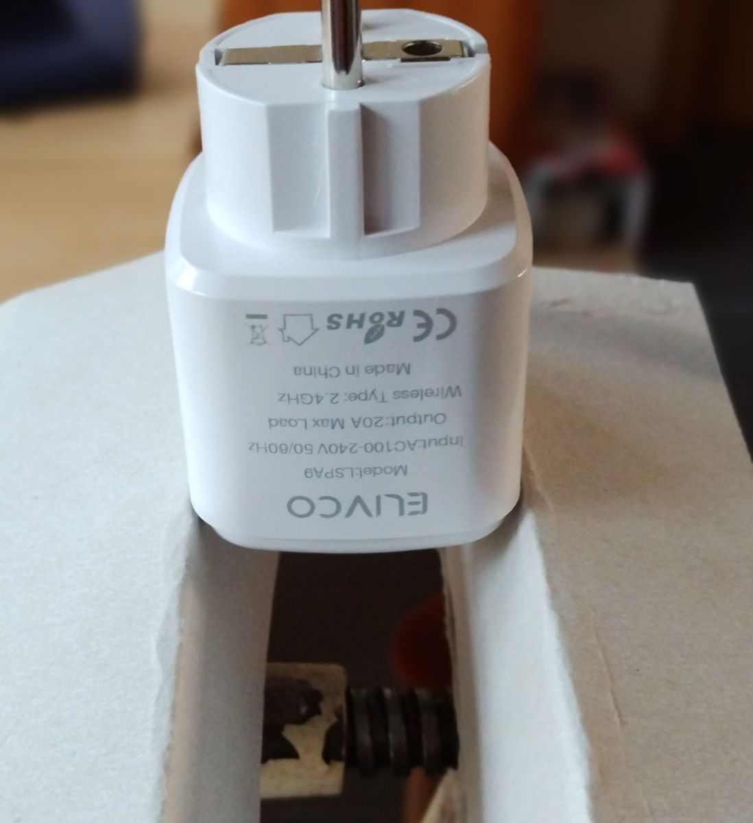
    Electric plug placed between two wooden boards. ELIVCO plug held in a vise, viewed from the socket side.
    Turn the plug to put pressure on both sides. You will hear a light crack when glue is broken; you might also support the pressure by some light bending of the socket.
    (If you hear a loud crack, you probably applied to much pressure ;-) but I already opened five devices and never broke one...)
    Just keep pressing and turning the sides until the device pops open.

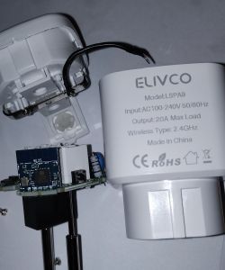
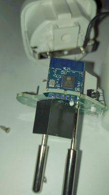
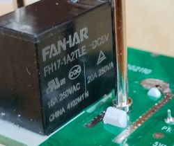
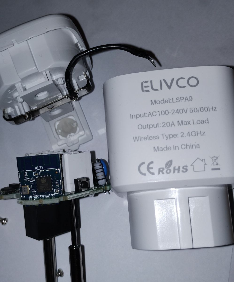
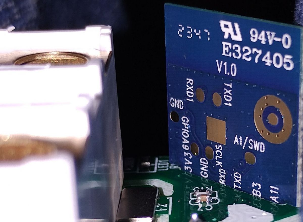
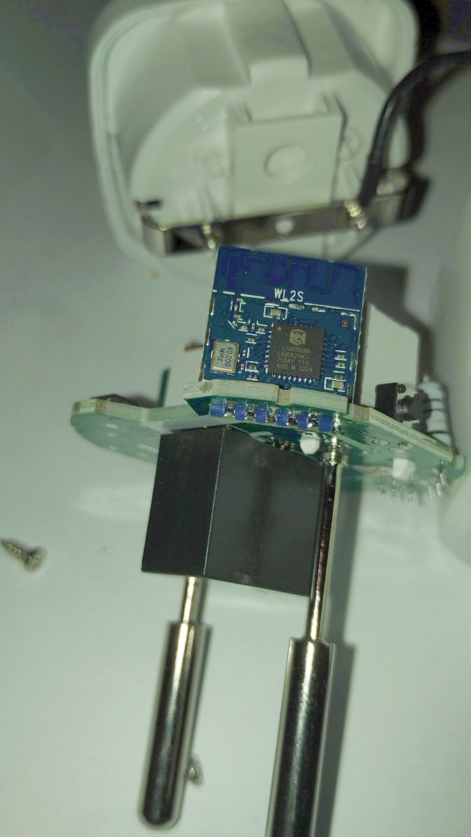
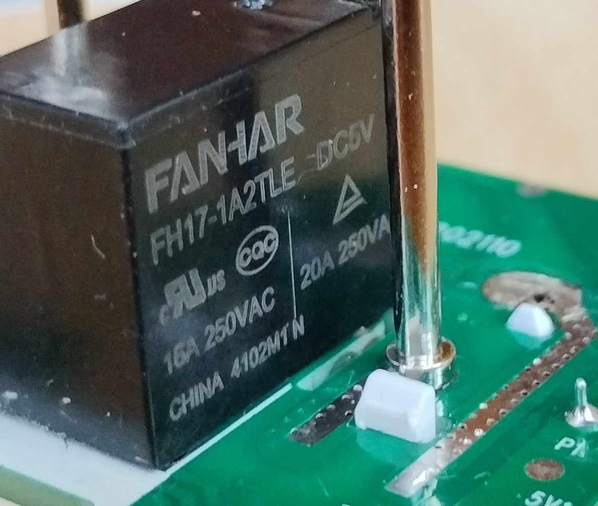
    The inside is a BSD342-2110 PCB with "WL2S" labeled LN882H module and BL0937 energy metering chip. The relay shows 16A and 20A, so it's your choice, what to believe ;-):
    ELIVCO model LSPA9 plug with removed casing, showing internal PCB with WL2S module.

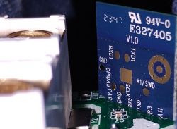
    Close-up of PCB with LN882H module and markings. Image showing the inside of a device with a WL2S PCB. Image of a FANHAR FH17-1A2TLE-DC5V relay on a PCB.

    The bootlog for the shipped firmware is visible on Tx1 (UART1 is on the back side of the WL2S module), but flashing is done via Rx0/Tx0 (soldered to main PCB).


    Now to some new findings (I hope): As I am a lazy guy, let me tell you, that in fact you only need to solder three wires :-)

    VCC (3.3 V)
    RX
    TX

    You can use the plugs power pin opposite to the LN882H module as GND - no need to solder here!
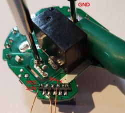
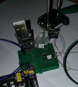
    Close-up of a PCB with labels VCC, RX, TX, and GND Breadboard with connected wires and USB module..
    If there was any doubt, now you know for sure that you should never try to use the free GPIOs outside the plugs case: For at least GND will be connected to the high voltage live wires!

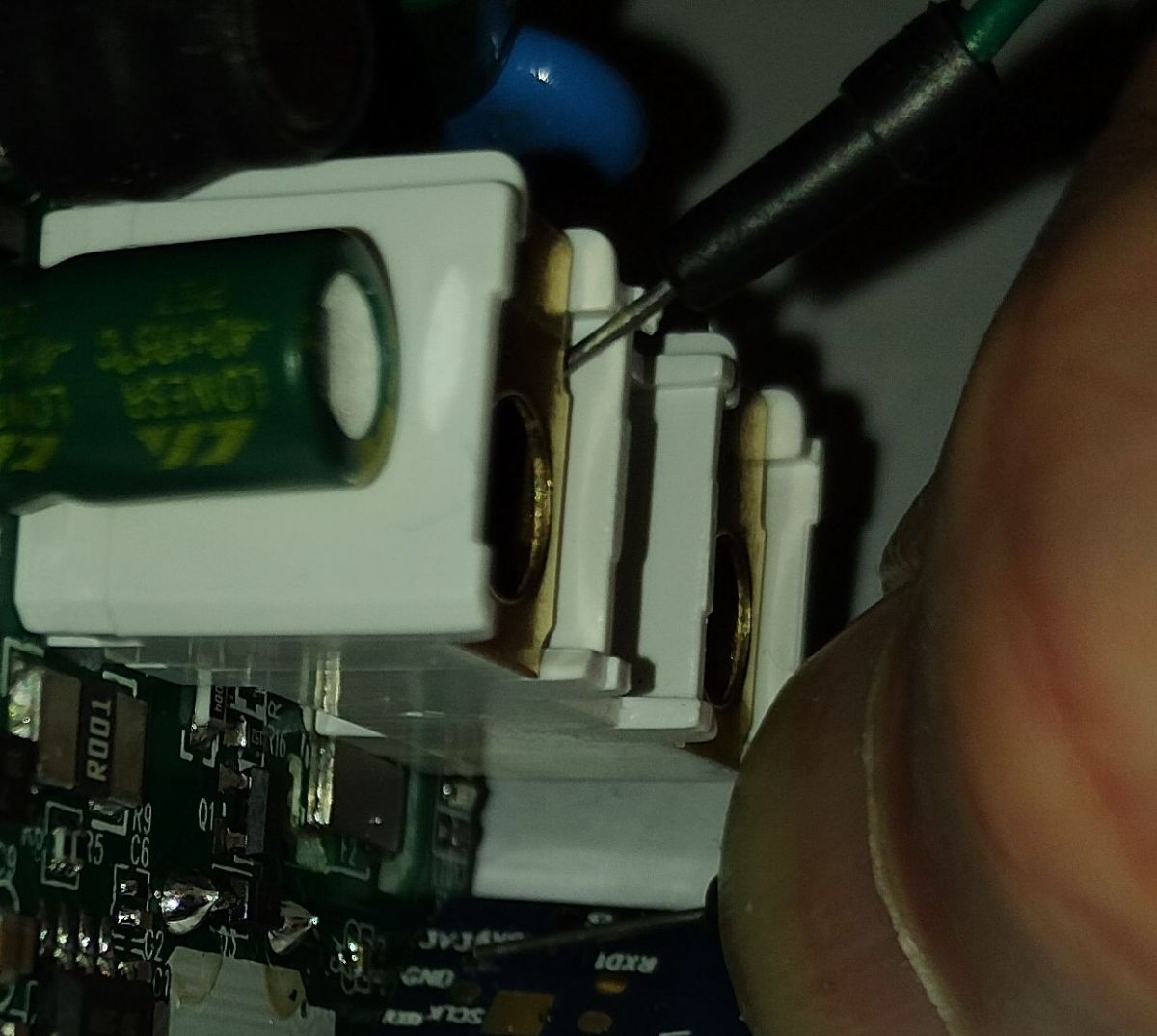
    Regarding flashing you need to short pin A9 to GND - but this was not necessary for the whole flashing process:
    I shortened A9 for some seconds after powering the device up - you will see if you missed the point, if the device starts flashing its LED.
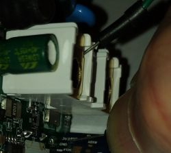
    Close-up of electronic components on a PCB with wires soldered to them.
    It works o.k. with the shown wires from a breadboard, for other plugs I used a testing pin from a multi-meter, this won't bend so easy.
    It didn't work every time, I had to give it some tries, but was successful with all plugs in the end.
    Remember, since we used the power pin for GND, we have it present on the upper outlet socket, as you can see on the picture.

    For you might need to retry several times: If your PCs keyboard is not reachable from the plug while shortening the pin, I had a small batch file running to retry every five seconds.

    Just to show off, I pimped my simple batch a bit ;-)

    @echo off
    echo List of serial ports (with some text about status):
    echo.
    echo and all .bin files
    dir *.bin  | findstr .bin
    echo.
    echo.
    mode | findstr COM
    echo.
    echo.
    
    :pset
    set p=-10
    set /p p="Enter COM-Port number: "
    if +%p% NEQ %p%   (
    	@echo please only provide numbers
    	goto pset
    )
    (mode | findstr COM%p%: >Nul || (
    	@echo COM%p% not found
    	goto pset
    ))
    
    :fset
    set /p f="Enter filename: "
    if NOT exist %f% (
    	@echo Can't find file %f%. Please chek and try again.
    	goto fset
    )
    
    :loop
     LN882H_CMD_Tool.exe COM%p% download flash 115200 0x0 %f%
     timeout /t 5
    goto loop


    Then flashing with the speed of 115200 (I didn't manage to use 200000, that might be, because of too long wires, the PCB not desoldered but still in the plugs PCB, or some other reason).


    Thanks again to all the brave people working on the Openbeken port for this chip!

    Here is my template for the device:
    Quote:
    {
    "vendor": "Elvico",
    "bDetailed": "0",
    "name": "Elvico LSPA9",
    "model": "LSPA9",
    "chip": "LN882H",
    "board": "BSD342-2110",
    "flags": "1024",
    "keywords": [
    "BSD342-2110",
    "LN882H",
    "BL0937"
    ],
    "pins": {
    "0": "LED_n;0",
    "3": "Btn;0",
    "7": "BL0937CF1;0",
    "10": "WifiLED_n;1",
    "11": "Rel;0",
    "12": "BL0937CF;0",
    "19": "BL0937SEL;0"
    },
    "command": "",
    "image": "https://obrazki.elektroda.pl/5522980200_1708165078.jpg",
    "wiki": "https://www.elektroda.com/rtvforum/topic4036567.html"
    }


    Please also see the posts by @divadiow Link and by @sithyoda Link.

    The flashing tool is present e.g. in the LN882H flashing guide by @p.kaczmarek2
    or can be downloaded here:
    https://gitee.com/lightningsemi/ln882h-docume...%BB%A4%E8%A1%8C%E5%B7%A5%E5%85%B7_V1.0.16.zip (use "save as" on the shown download link, for at least for me it would otherwise only show the raw binary - missing mime type I suspect)

    Have fun!

    Cool? Ranking DIY
    About Author
    max4elektroda
    Level 24  
    Offline 
    max4elektroda wrote 746 posts with rating 184, helped 48 times. Been with us since 2024 year.
  • ADVERTISEMENT
  • #2 20965704
    miegapele
    Level 16  
    Posts: 173
    Help: 15
    Rate: 29

    Which AliExpress shop this was bought? I would like ln882h lspa9 form socket for my collection 😂
  • ADVERTISEMENT
  • #3 20965724
    max4elektroda
    Level 24  
    Posts: 746
    Help: 48
    Rate: 184

    It was bought at Digitaling Store, and this is the Link to the plug.

    But, since this was some weeks ago, you can never be sure, you will get the same device, if you order it now ;-)
  • #4 21004486
    Raufaser
    Level 10  
    Posts: 47
    Help: 3
    Rate: 15
    I bought the same plug as OP. I can see on the order details that it is even the same item number on AliExpress.

    Here is my plug and package:
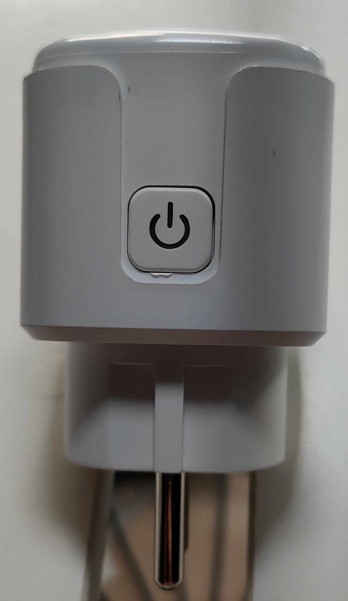
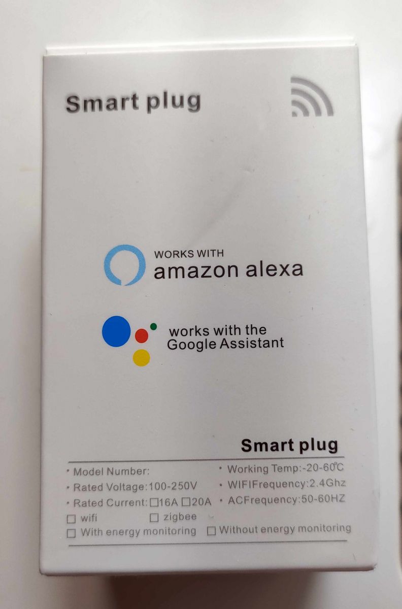
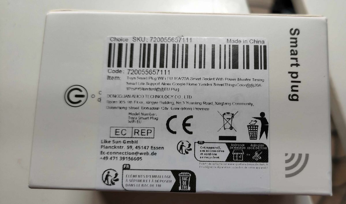
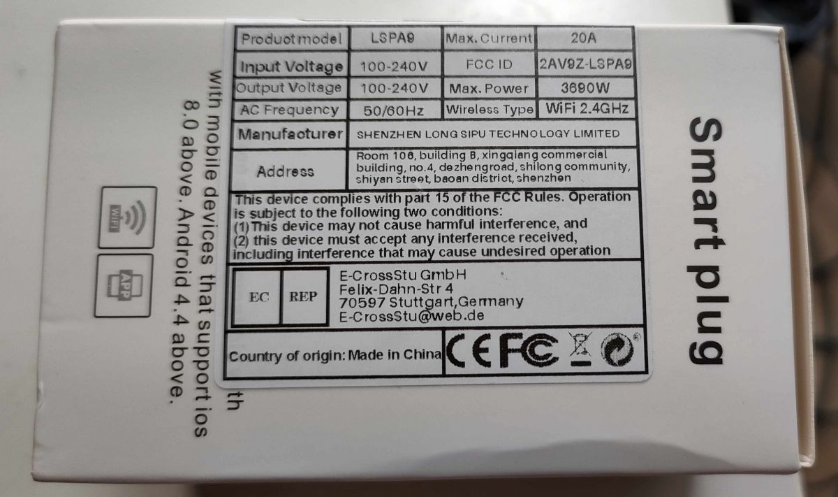
    Close-up of an ELIVCO smart plug with technical specifications. White plug with a power button on the front. Smart plug packaging with Amazon Alexa and Google Assistant information. Label of Tuya smart plug packaging with SKU, barcode, and manufacturer information. Smart plug packaging with technical specifications and manufacturer information.

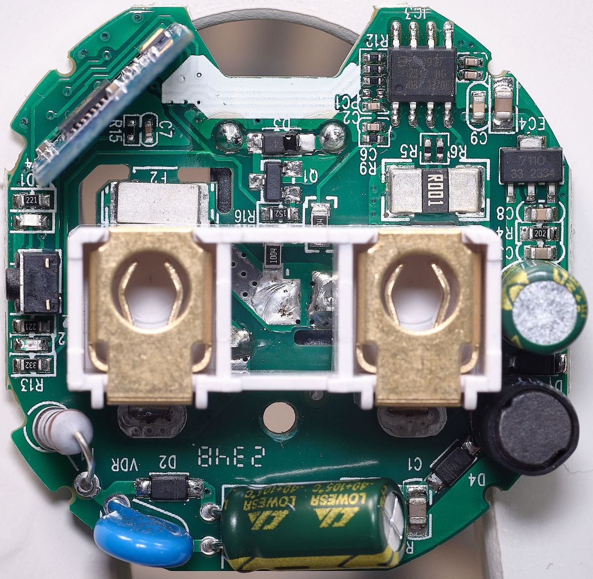
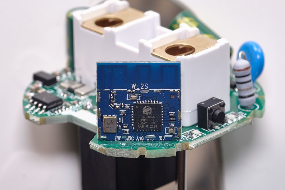
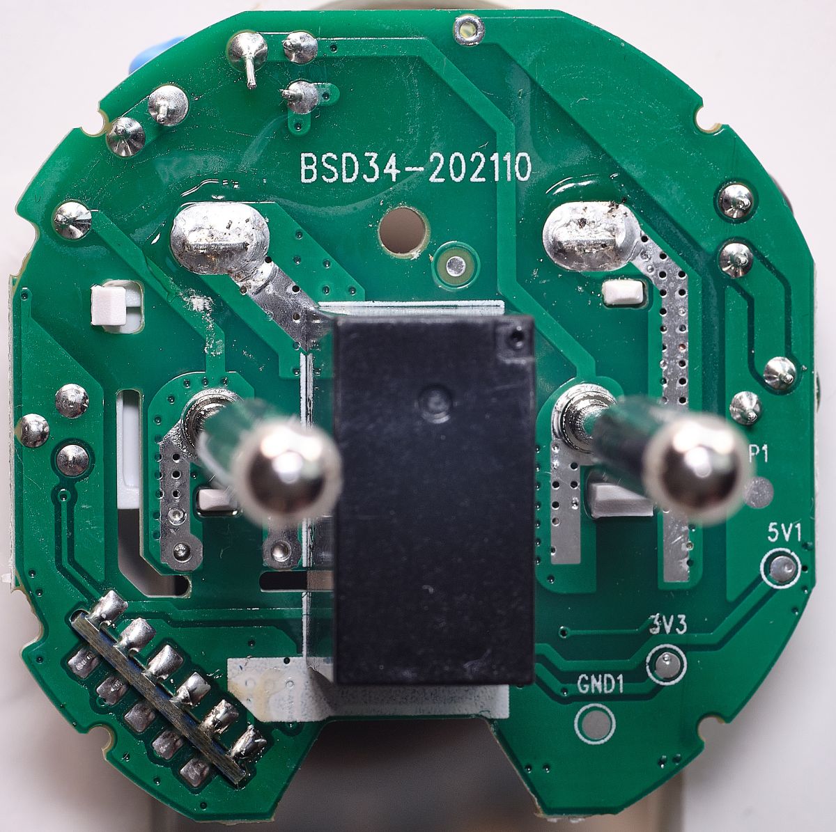
    And some high res pics of the internals. Maybe useful for someone:
    Close-up of the interior of an electronic USB plug showing components. Close-up of an electronic module WL2S mounted on a printed circuit board. Image of the interior of an electronic plug with visible circuit components and marking BSD34-202110.

    Before flashing the Open Firmware i dumped the original one:
    LSPA9_o...bin (1 kB)You must be logged in to download this attachment. LSPA9_fl..h.bin (2 MB)You must be logged in to download this attachment.

    Until now, everything works well :)
  • #5 21015608
    Raufaser
    Level 10  
    Posts: 47
    Help: 3
    Rate: 15
    The device seems to be very unstable. Longest uptime was around 48h. It just disappears from the network after a certain amount of time.
    Also all firmwares from 1.17.513 and later are not really booting up. The instantly restart. Sometimes they run for the amount of time needed to reflash a different version via Webapp.

    Added after 9 [minutes]:

    I noticed that the firmwares >512 running OK when i only access the plug via Webapp. As soon as I try to access it via the normal Web-GUI it hangs for about 20 - 30 seconds.
  • #6 21022643
    rufus4
    Level 11  
    Posts: 65
    Rate: 9
    Hi @ all,
    for me its working fine with latest version (OpenLN882H_1.17.521.bin) Web GUI and Web App are working smooth.
    Once I got kicked out of networkaccess after doing some settings with reboot. Only reflash to vendors FW did solve it. Dont know what the problem was.
    Stability I do have to test still. Playing arround since yesterday only.

    A other thing I want to ask.
    How do I need to set the button to control the relais manualy and what action does the button with the setting "3": "Btn;0" ?
  • #7 21022708
    max4elektroda
    Level 24  
    Posts: 746
    Help: 48
    Rate: 184
    rufus4 wrote:

    A other thing I want to ask.
    How do I need to set the button to control the relais manualy and what action does the button with the setting "3": "Btn;0" ?

    This setting should control the button 😀!
    It defines pin 3 (A3) as control input for channel 0.

    If it doesn't work as expected, maybe you defined your relay to another channel (see the number after the relay, in this case pin 11 with channel 0: "11": "Rel;0", )?
    Or your layout is different, and you need to set another pin for it.
    Then you might want to use the pin doctor from web application to search the correct pin.
  • #8 21022878
    rufus4
    Level 11  
    Posts: 65
    Rate: 9
    thanks!

    I have the BSD34-202110 bord like @Raufaser . Yours is BSD342-2110 if this is correct?
    Channel is the same. Seems like button needs another pin setting then.
    ----------
    solved!
    The push-button on my device is crap. I had to press it with some more power to make contact.
    Well these thingies take a lot of attention. :)
    ----------

    Does start value for channel 0 with "-1" work for you?
    (I`m scared to try because last time messed up device with this setting.)

    --update--
    Kept my fingers crossed and did set channel 0 to "-1" for startup... and it works without any problems. :)
  • #9 21023427
    max4elektroda
    Level 24  
    Posts: 746
    Help: 48
    Rate: 184
    Just when I made it to try - yes it works, regardless if there is power loss or it's restarted via GUI ;-)
  • ADVERTISEMENT
  • #10 21023618
    rufus4
    Level 11  
    Posts: 65
    Rate: 9
    max4elektroda wrote:
    Just when I made it to try

    kkk... thanks anyway

    Next will hopefully be a working "powersave" on the LN882.
    Tomorrow I try to find some time to mesure power consumption of the hole unit from the AC side. I think it is too much at the moment. Device gets quiet hot.
    Microprocessor temperature is about 60°C with "powersave 0" inside LSPA9 enclosure. And around 40°C with "powersave 1".
    But after some time the device seems to fall a sleep with non responsing GUI. So it`s not working yet.
  • #11 21024659
    rufus4
    Level 11  
    Posts: 65
    Rate: 9
    Today I was playing arround with my multimeter to mesure the powerconsumption of the LSPA9.
    First I had to realise that powermesuring needs to be done with a osciloscope to get reliable results, because the consumption is not contant and has got fast changing low and hight peaks.

    But mesuring even with the multimeter high powerconsumption can be noticed on this device with the beta OpenFW without any working powersave mode.
    So its not recommended to use the device yet in a daily usecase. It`s getting just to hot.

    Mesured with a ammeter: LSPA9 without powersave, relais off 8,5mA and 12,5mA with relais on. That`s inbetween 2 and 3Watts!
    This is about the double of what I mesured of a Shelly Plug (16A)
  • #12 21024677
    Raufaser
    Level 10  
    Posts: 47
    Help: 3
    Rate: 15
    Yo dawg, I heard you like power measurements. So i put a Beken in line with your Beken, so you can measure the power consumption of measuring the power consumption.

    🤣

    But seriously, how did you measure with your multimeter? And how would you do with a scope? I am interested in this too.
  • #13 21024780
    rufus4
    Level 11  
    Posts: 65
    Rate: 9
    I do have a good quality DMM from Brymen to measure inline and a good and payable clamp meter (UNI-T UT211B). They show +/- the same.
    With an oscilloscope I think you do it with a shunt resistance and measure before and after that. Then you get the voltage difference to calculate the amps. There you can measure and record all the spikes and as well average. I do have a beginners osci, but didn't find the time to play with it and learn how to measure this.

    Back to the LSPA9.
    I did flash original fw and this unwanted tuya app to see its consumption and it looks like not even them have got a powersave running. It's taking 8 and 12.5mA what is the same like with the OpenBekenFW.
    That's very interesting!
  • #14 21034099
    rufus4
    Level 11  
    Posts: 65
    Rate: 9
    --update and observations--
    PowerSave 1 still needs to be set manually after the device has booted. But my LSPA9 is stable since more than three days without any interrupts or hanging in the GUI. (OpenLN882H_1.17.530_OTA.bin)
    DHT still doesn`t work yet.
    All in all its not far away from good stability for daily use.
  • ADVERTISEMENT
  • #15 21034356
    Raufaser
    Level 10  
    Posts: 47
    Help: 3
    Rate: 15
    Good to hear that yours is running stable. I can report mine is running stable too. For almost a week now. It is in use 24/7 measuring the consumption of my "always on" Tiny-PCs 👍

    Software version and uptime information.
  • #16 21059991
    Raufaser
    Level 10  
    Posts: 47
    Help: 3
    Rate: 15
    Is it possible to add the device to the device list? The Elvico LSPA9, that are in the list have different pin settings.
  • #17 21060004
    io2345
    Level 9  
    Posts: 267
    Help: 1
    Rate: 7
    Has probably nothing to do with Hardware or Flashing, but might depend on the used Tasmota Firmware: How to switch this device from IObroker? I can read the device via MQTT and also can see a state "mqtt.0.<MQTT_Client_Topic>.0.get" alternating from 0 to 1 when switching the plug with button or from the Tasmota-Webpage. But changing this value in ioBroker doesn't change the state of the plug. Anyone with a solution?
  • #18 21063201
    io2345
    Level 9  
    Posts: 267
    Help: 1
    Rate: 7
    With the help from some guys on ioBroker-Forum, I managed to get basic switching functionality in ioBroker: You have to create a manual entry in the mqtt.0 device-tree (using Expert Mode): mqtt.0.cmnd.<Client Topic name of the Device>.POWER
    After some time you will also get an additional entry mqtt.0.stat.<Client Topic name of the Device>.RESULT, which shows the state of the device in JSON type like "{"POWER": "OFF"}". This entry is automatically created.
    They said, that in Tasmota there should also an entry be automatically created
    mqtt.0.stat.<Client Topic name of the Device>.POWER
    but this is not the fact. I only get ...RESULT there.

    After adding the value POWER manually in the device-tree, you have to be patient. The device will switch occasionally for some minutes, while MQTT "balancing" takes place (I guess). Once the main page of the device shows in green "MQTT state: connected" and stays that way, things will be ok.

    Some issues: You can switch the device from within the field mqtt.0.cmnd.<Client Topic name of the Device>.POWER by sending payload "0" or "1" as number. Sending as logical value (boolean) does only work for "false" but not for "true". Same (but opposite way) applys to sending the string TOGGLE - it only works, if the device is currently in "off"-state.

    Next downside: If you switch the plug manually (using the hardware switch on the plug), the state of the plug does not change in ioBroker. You can't even change it by overwriting the POWER value with the desired number, so you have to use the opposite value first and then the desired value to change state.

    Any idea how to fix that?
  • #19 21063422
    max4elektroda
    Level 24  
    Posts: 746
    Help: 48
    Rate: 184
    Sorry, I never used the plug like that, so I can't help here
  • #20 21064195
    io2345
    Level 9  
    Posts: 267
    Help: 1
    Rate: 7
    Alright. Do you mean, you never switch the plug using the hardware button on the plug?
    Btw: Is there a data point for your plug that reflects the state of this button, meaning: indicating, if it is pushed? Can it be, that this input (information that button is pushed) isn't implemented yet? Maybe I have to ask @p.kaczmarek2 about that, right?
  • #21 21064249
    max4elektroda
    Level 24  
    Posts: 746
    Help: 48
    Rate: 184
    io2345 wrote:
    Alright. Do you mean, you never switch the plug using the hardware button on the plug?

    No, I do use the button, too, but not mqqt...
    If I press the button, the relais switches and this is reflected in the GUI after the next update (every 3 seconds or so, when power metering values are updated)
  • #22 21064281
    io2345
    Level 9  
    Posts: 267
    Help: 1
    Rate: 7
    I see - you're only using the device's webpage to switch.

    All the others, who do use MQTT: Does your device tree change the values in
    mqtt.0.cmnd.<topic>.POWER
    and
    mqtt.0.stat.<topic>.RESULT
    when switching the plug with the hardware button?
  • #23 21064315
    Raufaser
    Level 10  
    Posts: 47
    Help: 3
    Rate: 15
    I am using all my sockets with MQTT and Homeassistant. It works out of the box. When switching on or off using the hardware button, the view in homeassistant is updated accordingly.

    Here is what happens on MQTT when switching the socket on and off using the hardware button:

    Message 8 received on smartsocket003/0/get at 12:38 PM:
    0
    QoS: 1 - Retain: false
    
    Message 7 received on smartsocket003/0/get at 12:38 PM:
    1
    QoS: 1 - Retain: false


    smartsocket003 is the client topic set in the socket's MQTT config form.
  • #24 21064461
    io2345
    Level 9  
    Posts: 267
    Help: 1
    Rate: 7
    You're right, it does send MQTT message on button press, according to the Device's webpage log.

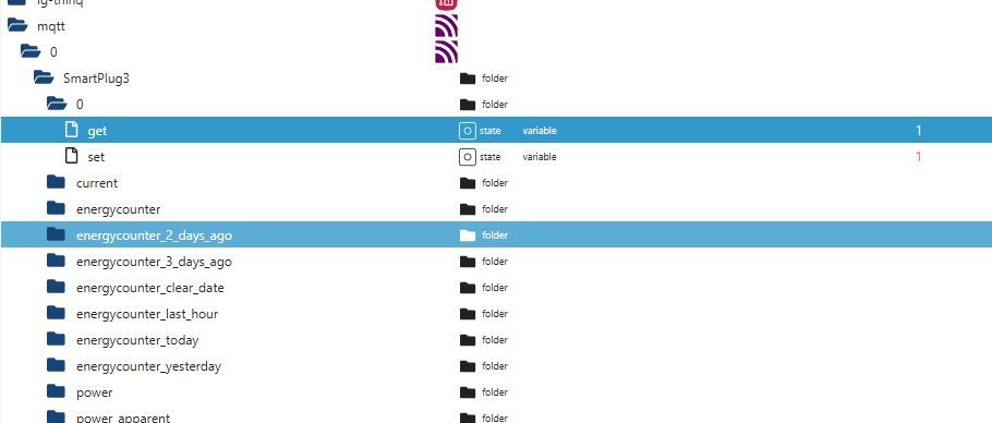
    The solution for ioBroker is much easier than expected: There is no need to have cmnd- and stat-tree in mqtt-adpater-tree at all.
    Instead, create a new entry in the same folder, where the "get" value is displayed, with the only difference that it says "set".
    So, all you do is create a new state with name "set" as type "number" and role "variable" (readable and writeable) under the objects-tree

    mqtt.0.<your_client_topic_name>.0.

    Screenshot of ioBroker folder tree highlighting the get and set states.

    The "set" value is used to actually switch the device remotely, whereas the get value reflects the current state of the plug, which can also be changed by pressing the hardware button on the plug.
  • #25 21067066
    io2345
    Level 9  
    Posts: 267
    Help: 1
    Rate: 7
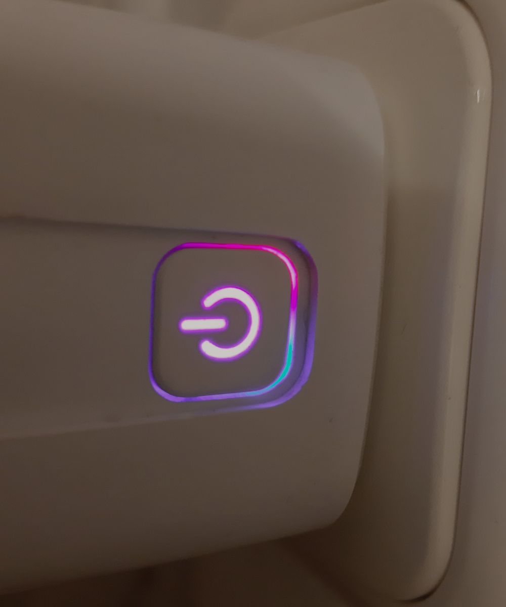
    Last (?) question: The LED on the plug is in Tuya-Version blue when plug is switched off and red when plug is on.
    In OpenBK version the LED is blue when off, but purple when on, because both blue and red LED inside are lit. Can this be changed to red?

    Power button icon on a plug with purple backlight.
  • #26 21067095
    rufus4
    Level 11  
    Posts: 65
    Rate: 9
    You can set "WifiLED_n" to "WifiLED". Then WifiLED is only lit while connection process.
  • #27 21067125
    io2345
    Level 9  
    Posts: 267
    Help: 1
    Rate: 7
    Thank you, much better: LED off when Power off, LED red when Plug has Power. Perfect.
  • #28 21067385
    max4elektroda
    Level 24  
    Posts: 746
    Help: 48
    Rate: 184
    ... or, if you like the Tuya style, you can set A10 to "LED" and it will be blue if power is off.
    (If you use the plug in place with low light, I like to find the button without turning on the light ...)
    That's the good point in using OpenBeken: Just configure it to fit yor needs ;-)
  • #29 21832201
    io2345
    Level 9  
    Posts: 267
    Help: 1
    Rate: 7
    Did OTA-flash today a device with an older firmware (like 1.18.28) with the latest version 1.18.256. It went back to access point mode. Why?
  • #30 21832210
    insmod
    Level 31  
    Posts: 1372
    Help: 164
    Rate: 430
    That's strange, there were no changes in config for LN.

    Added after 2 [hours] 46 [minutes]:

    I downgraded to .237 and then upgraded to .256, config persisted.
📢 Listen (AI):

Topic summary

✨ The discussion revolves around the ELIVCO LSPA9 device, specifically the BSD342-2110 PCB variant equipped with LN882H and BL0937 components. Users share insights on opening the device, stability issues, and firmware performance. Some report successful operation with the latest OpenLN882H firmware, while others experience instability and high power consumption. Users discuss power measurement techniques, MQTT integration with ioBroker, and LED behavior customization. The conversation highlights the importance of firmware versions and settings for optimal device performance.
Generated by the language model.

FAQ

TL;DR: This FAQ shows how to open and flash the Elvico LSPA9 using only 3 wires and a brief A9-to-GND short; one contributor said, "you only need to solder three wires." It helps OpenBeken users identify the BSD342-2110 / LN882H / BL0937 variant, avoid cracking the glued case, and handle firmware issues such as reboots, heat, LED behavior, and MQTT control. [#20965239]

Why it matters: The LSPA9 exists in multiple hardware variants, so correct flashing points, pin mapping, and firmware expectations matter more than the product name.

Topic This LN882H BSD342-2110 variant Notes from the thread
Main SoC/module LN882H, WL2S-labeled module Not the common Beken-based variant
Metering chip BL0937 Power readings supported in OpenBeken
Flash entry Short A9 to GND for a few seconds after power-up Retry timing may be needed
Observed idle draw Approx. 8.5 mA relay off Reported with both Open firmware and vendor firmware
Observed temperature About 60°C with powersave 0, ~40°C with powersave 1 powersave 1 was not fully reliable early on

Key insight: Treat this plug as a board-specific target, not just an "LSPA9." The successful recipe is BSD342-2110 wiring, A9 boot shorting, and the matching pin template for A3, A10, A11, A12, and A19. [#20965239]

Quick Facts

  • Flashing worked at 115200 baud; one user could not make 200000 baud work on this board and wiring setup. [#20965239]
  • The confirmed UART setup uses 3.3 V, RX, and TX, while a mains-side power pin opposite the module was used as GND during bench flashing. [#20965239]
  • Early OpenLN882H reports showed instability, with the longest uptime around 48 h before the plug disappeared from the network. [#21015608]
  • Reported AC-side current draw was about 8.5 mA with relay off and 12.5 mA with relay on, roughly 2–3 W. [#21024659]
  • Reported internal temperature was about 60°C with powersave 0 and about 40°C with powersave 1, but the GUI could stop responding after some time. [#21023618]

How do you safely open the Elvico LSPA9 smart plug without damaging the glued case?

Open it by compressing the glued sidewalls evenly until the light adhesive bond cracks. 1. Protect the housing with thick paper or cardboard. 2. Squeeze the sides gently in a vice, then rotate the plug to load both side pairs. 3. Keep steady pressure and add slight bending until the case pops apart. A light crack is normal; a loud crack means you used too much force. The author opened five units this way without breaking one. [#20965239]

What are the correct UART wiring points for flashing the BSD342-2110 PCB with the LN882H WL2S module?

Use three soldered wires: 3.3 V, RX, and TX on the main PCB pads for UART0. The boot log appears on Tx1, but flashing uses Rx0/Tx0. You can use the plug’s power pin opposite the LN882H module as GND, so no GND wire must be soldered. That shortcut is convenient on the bench, but it also proves the exposed ground reference sits next to live mains parts and must never be brought outside the case. [#20965239]

Which pin assignments and OpenBeken template work for the Elvico LSPA9 with LN882H and BL0937?

The posted working template maps A0 to LED_n;0, A3 to Btn;0, A7 to BL0937CF1;0, A10 to WifiLED_n;1, A11 to Rel;0, A12 to BL0937CF;0, and A19 to BL0937SEL;0. It identifies the device as Elvico LSPA9, board BSD342-2110, chip LN882H, with keywords BSD342-2110, LN882H, and BL0937. Another user reported a different LSPA9 board marking, so verify your PCB before copying the mapping. [#20965239]

Why does the LN882H on this LSPA9 need A9 shorted to GND during flashing, and how long should that short be held?

It needs A9 briefly grounded to enter the flash-ready boot state after power-up. Hold A9 to GND for a few seconds right after applying power, then release it; it did not need to stay shorted for the whole transfer. If you miss the timing, the LED starts its normal flashing pattern and you must retry. One user looped the flashing command every 5 seconds because entering this mode did not work on every first attempt. [#20965239]

What is the BL0937 chip in the Elvico LSPA9, and what does it measure?

The BL0937 is the plug’s energy-metering IC, and the template shows it feeding OpenBeken through BL0937CF, BL0937CF1, and BL0937SEL pins. > "BL0937 is an energy-metering chip that measures electrical load data, using dedicated pulse outputs and a select line for integration with the main controller." In this LSPA9, users relied on it for power updates shown in the GUI about every 3 seconds. [#21064249]

What is the LN882H module, and how is it different from the Beken-based plugs people often flash with OpenBeken?

The LN882H is the Wi-Fi control module used on this LSPA9, and this unit carries a WL2S-labeled LN882H module on a BSD342-2110 PCB. > "LN882H is a Wi-Fi module family that runs the plug’s main firmware, using a different platform and flashing flow than the Beken chips commonly seen in OpenBeken devices." In practice, users here had to use LN882H-specific flashing steps, including Rx0/Tx0 wiring and the A9-to-GND boot short. [#20965239]

Why do some OpenLN882H firmware versions after 1.17.512 reboot or hang on the normal Web GUI while the Web App still works?

Some builds after 1.17.512 showed a board-specific stability issue on this plug. One user reported that versions from 1.17.513 upward instantly restarted, or ran only long enough to reflash. The same user found that the Web App could still work while the normal Web GUI hung for 20 to 30 seconds. Later reports improved: version 1.17.521 was smooth for another user, and 1.17.530_OTA ran stably for more than 3 days with PowerSave 1 set manually after boot. [#21015608]

How should the hardware button be configured in OpenBeken so pin A3 controls relay channel 0 on the LSPA9?

Set pin A3 as Btn;0 and set the relay pin to the same channel, Rel;0. That makes A3 the control input for relay channel 0. If pressing the button does nothing, first check that the relay is not assigned to another channel. If channels match, test for a hardware issue; one user solved the problem after finding the push-button needed extra force to make contact. [#21022708]

What does setting channel 0 startup value to -1 do in OpenBeken, and how does it behave after power loss or reboot?

Setting channel 0 startup value to -1 worked as a valid retained-start behavior on this device. Two users tested it and confirmed it behaved correctly after both power loss and GUI-triggered reboot. One user explicitly said the device worked “without any problems” after changing channel 0 to -1. That makes -1 a usable startup option on this LSPA9, even though one tester was initially afraid it might brick the unit. [#21023427]

How do you measure the real AC-side power consumption of the Elvico LSPA9 accurately, and why might a multimeter miss fast current spikes?

Measure it with a scope-based current method if you want accurate AC-side power. A multimeter can show average current, but it will miss fast peaks because this plug’s consumption changes quickly. One contributor recommended a shunt resistor and oscilloscope so you can capture the voltage drop, calculate current, and record spikes over time. Their DMM and clamp meter agreed roughly, but they still concluded an oscilloscope was needed for reliable results. [#21024780]

Original Tuya firmware vs OpenBeken on the LN882H LSPA9: how do stability, power consumption, and heat compare?

They looked surprisingly similar in power draw, while Open firmware matured over time in stability. One user measured about 8 mA with relay off and 12.5 mA with relay on under original firmware, matching OpenBeken figures. Heat also remained a concern, with reports around 60°C at powersave 0. Stability was mixed early, but later users reported more than 3 days and nearly 1 week of stable 24/7 use on newer OpenLN882H builds. [#21024780]

How can I make the LSPA9 LED show red when the relay is on instead of purple in OpenBeken?

Change A10 from WifiLED_n to WifiLED if you want red-on and off-off behavior. The purple effect came from both the blue and red LEDs being active when the relay was on. After switching A10 to WifiLED, one user reported the result as “LED off when Power off, LED red when Plug has Power.” If you prefer the original Tuya-style locator glow, another user suggested assigning A10 to LED instead. [#21067125]

What is the difference between assigning A10 as WifiLED_n, WifiLED, or LED on this smart plug?

WifiLED_n keeps the second LED active in the inverted Wi-Fi role, which caused blue-plus-red and a purple on-state for one user. WifiLED limits that LED mainly to the connection phase, so the plug ended up off when off and red when on. LED gives the Tuya-like locator style, with blue visible when power is off. The thread treats A10 as the behavior switch for how the front dual-color indicator is used. [#21067385]

How do you control the Elvico LSPA9 from ioBroker over MQTT, including which set/get datapoints to create manually?

Use the socket’s local topic tree, not the separate cmnd and stat trees. 1. In ioBroker expert mode, create mqtt.0.<client_topic>.0.set as a readable and writeable number state. 2. Write 0 or 1 to set for OFF or ON. 3. Read current state from mqtt.0.<client_topic>.0.get, which also changes when you press the hardware button. One user first tried cmnd/.../POWER, but later confirmed the simpler set/get method worked better. [#21064461]

How can the Elvico LSPA9 with BSD342-2110 be added to the OpenBeken device list when existing LSPA9 entries use different pin mappings?

Add it as a separate board variant with its own pin map, not as a generic LSPA9 clone. A user noted the existing LSPA9 entries used different pin settings, while this thread documented a BSD342-2110 board with LN882H and the mapping A3 button, A11 relay, A7/A12/A19 for BL0937, and A10 for the second LED. The practical fix is to submit this exact template as a distinct device-list entry for the BSD342-2110 hardware revision. [#21059991]
Generated by the language model.
ADVERTISEMENT