logo elektroda
logo elektroda
X
logo elektroda

Set - DC / DC converter 9A XL4016 and panel meter DSN-VC288, assembly, test

TechEkspert 77313 166
ADVERTISEMENT
Treść została przetłumaczona polish » english Zobacz oryginalną wersję tematu
  • #31 17476225
    adamas_nt
    Moderator of Programming
    I wanted to use it in the car as a power supply for a variety of such ... And everything worked out beautifully until I started the engine :(
    Set - DC / DC converter 9A XL4016 and panel meter DSN-VC288, assembly, test

    Input capacitor too small? What to do so that there is no boom again with the alternator running?

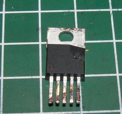
    And most importantly: Is there anyone in the XL4016 chip stock? On Alle ... as for anger, there is no, and I found it on the Internet for $ 0.65, where the shipping cost is 5x the purchase cost: /

    best regards
  • ADVERTISEMENT
  • #32 17476263
    sylweksylwina
    Moderator of Computers service
    Capacitor probably not, it's hard to say why this happened. This module withstands much higher voltages.
  • #33 17476670
    E8600
    Level 41  
    How to increase the maximum current of the system.


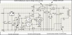
    Layout diagram.
    Set - DC / DC converter 9A XL4016 and panel meter DSN-VC288, assembly, test
  • #34 17478020
    adamas_nt
    Moderator of Programming
    It seems to me that it is not the current (the load was a reflector bulb), but the voltage changes at the input (the alternator only has a bridge).

    Noo! But he can do that for a welder :) Awesome...
  • #35 17480708
    E8600
    Level 41  
    adamas_nt wrote:
    Input capacitor too small? What to do so that there is no boom again with the alternator running?

    In my opinion, those shoddy precision potentiometers are to blame. I had something similar in another MT3608 converter where the same potentiometer works as it wants. Right out of the box it didn't work at all. They are probably tarnish inside or not folded properly.

    In the case of a colleague, starting the engine and the related vibrations could cause the loss of resistance of the potentiometers and excitation of the system to too high power.
  • ADVERTISEMENT
  • #36 17482845
    Justyniunia
    Level 36  
    Does anyone know what the second LED is for, i.e. it would be if it were mounted? I want to build a regulated power supply, but apparently it is a misfire on linear potentiometers.
    I have 2pcs of 10k and 2pcs of 1k for coarse and fine adjustment.
  • #37 17482971
    Dżyszla
    Level 42  
    Justyniunia - I will be putting 10k + 1k linear on voltage in the near future. I will write what it looks like then.

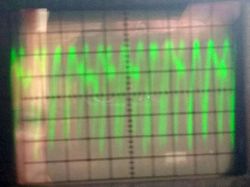
    Meanwhile, the course of the deviation at 5V / 0.9A, CV work. Vertical division 2mV. Forgive the old Russian oscilloscope, the blurry photo and the lack of something to blame it Set - DC / DC converter 9A XL4016 and panel meter DSN-VC288, assembly, test :)
  • ADVERTISEMENT
  • #38 17483277
    Justyniunia
    Level 36  
    If that didn't work out, I have a second idea.
    Potentiometer e.g. 1k and range switch.
  • #39 17483417
    Dżyszla
    Level 42  
    I'm afraid it would be fun with the range selector. Unless you still have to do, for example, the possibility of connecting parallel to the potentiometer to change the entire characteristic. Well, maybe I can make time next weekend. I will definitely share the results.
  • #40 17483497
    CMS
    Administrator of HydePark
    Gentlemen and ladies, I do not understand your polemics. The solution with two potentiometers (coarse and fine) has been proven for years and works. Why reinvent the wheel?
  • #41 17486059
    Justyniunia
    Level 36  
    My fears stem from this:
    https://www.elektroda.pl/rtvforum/topic3434421.html
    eurotips wrote:
    The factory ones are linear and only thanks to the multiturns used, you can set anything with them. The linearity of regulation on these peers is terrible. There you need a potentiometer with characteristics similar to logarithmic, unfortunately you do not find such potentiometers at reasonable prices.

    eurotips wrote:
    As for the minimum, you have 1.2V, you have 3.0V in half
    You have 5V for 3/4 turn and the rest of the small part is the rest, i.e. the 5-30V range.

    Szyszkownik Kilkujadek wrote:
    But it is about the characteristics of the potentiometer, it would have to be a miracle of the M + N type used in audio, something that nobody produces in series.


    Added after 6 [hours] 12 [minutes]:

    Voltage regulation checked.
    For the 10k potentiometer there is no change from halfway up
    (we're already half full of tension)
    The situation was improved by a 14-15k resistor in parallel with the potentiometer.
    There is a place for such an SMD resistor on the bottom of the board.


    The 10k potentiometer is used to regulate thicker values, while the 1k potentiometer allows for 3V adjustment, which is acceptable.
    I set 1k in the middle, with the 10k potentiometer I set "roughly" the voltage that interests me and with this 1k I choose the value precisely.

    As for the current regulation, the precise one does not work at all by. the diagram shown earlier, besides, there is probably an error - the current, voltage description changed.
    The precise regulation for the current allows you to operate with currents in the vicinity of 0 - 1A.

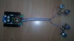
    I have it connected like this:
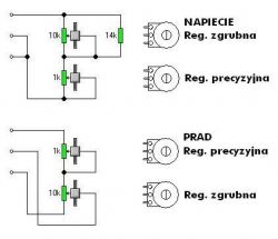
    Set - DC / DC converter 9A XL4016 and panel meter DSN-VC288, assembly, test

    Set - DC / DC converter 9A XL4016 and panel meter DSN-VC288, assembly, test

    Oh, for the curious:
    The converter is powered by a 24V / 5A switching power supply (overclocked to 27.5V).
    Panel meter powered from a separate 5VDC source, also supplying a small fan.
    Everything works.
  • #42 17487622
    Anonymous
    Level 1  
  • #43 17487635
    Justyniunia
    Level 36  
    In my case (regulated power supply), the converter will work with this 27.5V power supply.
    It is possible that a different resistor will have to be selected for a different UIn.
    Current regulation is just beginning to work, both coarse and precise.
    Before that, the precise one did not work at all, and the coarse one, after gently turning the knob, pounded a few A at once.

    Now, with the minimum precise position, I set the coarse current to e.g. 3A, for precision I can add about 1A (example)
    With the coarse to the minimum, I regulate the precise 0-1A.
    Precise in the middle, I set the coarse to 2A, I can adjust the precise 1.5A - 2.5A. e.t.c...
    After all, that's how it should work.

    Returning to the input voltage and the resistor at the potentiometer, tomorrow, out of curiosity, I will power it from 12V and see what the regulation looks like.
  • ADVERTISEMENT
  • #44 17490617
    Dżyszla
    Level 42  
    So for me it looks like when powering the 24V converter, the max grabs somewhere from 3/4 of the 10k potentiometer. I did according to the scheme (1 - 2 + 3) - (1 - 2 - 3) [what @CMS gave], where the first is 1k and the second is 10k
  • #45 17490905
    CMS
    Administrator of HydePark
    Dżyszla wrote:
    max grabs somewhere from 3/4 of the 10k potentiometer.


    And in what position do you have the "precise" potentiometer. We start the settings with the "coarse" potentiometer when the "fine" is turned to the minimum (default to the maximum left).
  • #46 17490971
    Dżyszla
    Level 42  
    At the minimum.
    This is exactly what it looks like:
    R1 - 10k, R2 - 1k:

    0%, 0% - 1.38V
    0%, 50% - 3V
    0%, 100% - 4.88V
    50%, 0% - 15V
    50%, 50% - 16.6V
    50%, 100% - 18.5V
    75% - max 24.6V
  • #47 17491028
    CMS
    Administrator of HydePark
    Hmmm, and these are definitely linear potentiometers? Let me remind you that the Chinese have "negative" markings in relation to, for example, Polish ones.
  • #48 17491034
    Justyniunia
    Level 36  
    I don't know about Chinese, but from what I can see, only our A's are linear, all other linear's are B.
  • #49 17491268
    Dżyszla
    Level 42  
    marked as B - linear. Although in fact, while 1k was 1k, this 10 was in fact 9.6k (basically my hand ;) ), which already says a lot :) Nevertheless - with an accuracy of 0.05V I can easily set it.
  • #50 17556241
    Heavy R
    Level 11  
    Hello, is the described converter suitable for the construction of a rectifier - charger for a 55 ah acid battery? Or is it better to stay with the classic transformer and bridge?
  • #51 17556846
    Anonymous
    Level 1  
  • #52 17557230
    CMS
    Administrator of HydePark
    Dżyszla wrote:
    1k was 1k so this 10 was actually 9.6k


    I remind you about the tolerance of 10% and the accuracy of the "gauge" used. 9.6k is the most correct value.
  • #54 17558892
    Heavy R
    Level 11  
    If we put a 10A rectifying diode at the output of the inverter, it would prevent the voltage from the battery from being recovered to the inverter (the only question is whether to one wire or to both + I -)?
  • #55 17559048
    sylweksylwina
    Moderator of Computers service
    Why both?
    Remember that the lower the voltage drop across the diode, the smaller the losses.
  • #56 17559564
    TechEkspert
    Editor
    Instead of a diode, it could be combined with a MOSFET.
  • #57 17559839
    Justyniunia
    Level 36  
    And the diode between + Vin and + Vout?
    Anode to the output and cathode to the input?
  • #58 17560000
    Anonymous
    Level 1  
  • #59 17567447
    Anonymous
    Anonymous  
  • #60 17591804
    ArturAVS
    Moderator
    Is it possible to increase the output current in a reliable and proven way? So let's say up to 20 - 25A?
    Someone tried?

Topic summary

The discussion revolves around the assembly and testing of a DC/DC converter based on the XL4016 chip, capable of outputting up to 9A and adjustable voltage from 1.2V to 35V, along with the DSN-VC288 panel meter for voltage and current readout. Users share experiences regarding circuit assembly, potential issues with reverse polarity connections, and methods for enhancing protection against such errors, including the use of Schottky diodes and relays. The conversation also touches on the practicality of using multiturn potentiometers for fine adjustments, the importance of proper grounding, and the challenges of using the converter for battery charging applications. Concerns about the reliability of components, particularly regarding counterfeit products, are also raised, emphasizing the need for quality assurance in electronic components.
Summary generated by the language model.
ADVERTISEMENT