logo elektroda
logo elektroda
X
logo elektroda

Set - DC / DC converter 9A XL4016 and panel meter DSN-VC288, assembly, test

TechEkspert 77316 166
ADVERTISEMENT
Treść została przetłumaczona polish » english Zobacz oryginalną wersję tematu
  • #61 17591866
    brofran
    Level 41  
    arturavs wrote:
    Someone tried?

    If he tried, it was probably only once. :cry:
    From such a small (dimensionally) module and small heat sinks there is no chance to get 2x more power.
    It is also problematic to power the converter from a switching power supply. I tried with ATX converted to 24V. Unfortunately, the power supply died at the first attempt to connect a current load around 5 A. But the converter "survived". :D
  • ADVERTISEMENT
  • #62 17591899
    sylweksylwina
    Moderator of Computers service
    Someone may have the module damaged by too high current? (I suspect it at least)
    Voltage regulation works, but current regulation does not (current flows even higher than the nominal maximum). What could be damaged?
  • #63 17591941
    ArturAVS
    Moderator
    brofran wrote:
    If he tried, it was probably only once. :cry:

    I do not mean "turning" this converter module to a higher current, but adding an additional transistor, replacing the choke to get 20A.
  • #64 17591961
    E8600
    Level 41  
    sylweksylwina wrote:
    Voltage regulation works, but current regulation does not (current flows even higher than the nominal maximum). What could be damaged?

    Check the current adjustment potentiometer with a multimeter if it smoothly adjusts the resistance. There was a similar case on the previous page.
  • #65 17592106
    Dżyszla
    Level 42  
    brofran wrote:
    It is also problematic to power the converter from a switching power supply.
    And why should the inverter have a problem? I power from impulse 24V / 96W, I added only 1000uF on the output and input of the converter and I used the laptop on it without any problems.
    When the power supply fell, it was probably not of good quality. I would not see the culprit in the inverter itself.

    Added after 1 [minutes]:

    arturavs wrote:
    I do not mean "turning" this converter module to a higher current, but adding an additional transistor, replacing the choke to get 20A.
    The capacitors are also worthwhile, necessarily heatsinks and ... In fact, you will build a new converter ;) I don't know if there is any point in having fun.

    Added after 58 [seconds]:

    sylweksylwina wrote:
    Voltage regulation works, but current regulation does not (current flows even higher than the nominal maximum). What could be damaged?
    I suspect a break ...

    The entire converter module has one terrible drawback - the break in the control (resistors) is the maximum voltage / maximum current.
  • #66 17593530
    ArturAVS
    Moderator
    eurotips wrote:
    Do you need a diode at all? the module was conceived as a charger, so it is enough for someone to take a little trouble and check what happens when he connects the battery without giving voltage to Vin


    I checked on the module received yesterday. I connected the gel 12V / 7Ah. The 30A series fuse has blown.
    An additional diode is not needed, the reverse current will flow through the choke and the diode contained in the module.
  • #67 17593821
    Anonymous
    Level 1  
  • ADVERTISEMENT
  • #68 17593846
    ArturAVS
    Moderator
    For testing purposes, I connected according to the diagram from # 1. Nothing happens except that the meter is working. I did not look at the board, but it looks like it can be powered from the measured voltage. Vin was fed from an 18V / 10A power supply, and disconnected during operation.
    With the 18650 cell connected, the blue LED on the inverter board slightly drizzled. I did not notice any other effects.

    eurotips wrote:
    protection is only a diode parallel to the output and a fuse on the output side.


    The fuse itself is enough.
  • #69 17621335
    zybex
    Helpful for users
    I have a question about the ammeter in this set. Does it show the current consumed, i.e. when there is no load, it shows nothing? Is it used to set the current limit and will it show the steady current even without a load?
  • #70 17621449
    kj1
    Electrician specialist
    zybex wrote:
    Does it show the current consumed, i.e. when there is no load, it shows nothing?
    Yes.
  • #71 17622579
    Dżyszla
    Level 42  
    More precisely - without load it shows zero :) It is an ordinary meter, it has nothing to do with the inverter.
  • #73 17624859
    Dżyszla
    Level 42  
    Yes, but from the point of view electronics are simply two completely independent elements and neither is necessary for the operation of the other - each of them carries out its own, separate activities :)
  • ADVERTISEMENT
  • #74 17747669
    lukaszek9876
    Level 11  
    Could someone tell me how to connect it to a rectifier such a panel meter where exactly which cable?
  • #75 17747799
    zybex
    Helpful for users
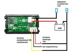
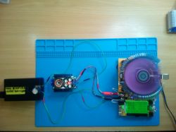
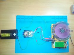
    Assuming you don't want to put a separate little power supply for the meter, your connection should look like this.

    Set - DC / DC converter 9A XL4016 and panel meter DSN-VC288, assembly, test
  • #76 17747926
    lukaszek9876
    Level 11  
    Everything in Polish explained on google you can find but I asked for an explanation which cable how to connect in Polish because I have a UPS rectifier transformer plus rectifier bridge and I know how to connect to show voltage but I do not know how to connect an ammeter it is a high scale for me so I need a simple explanation, not that you need a screwdriver to unscrew, everyone knows but when he asks for help, he writes clearly about what
  • #77 17748105
    Dżyszla
    Level 42  
    After all, it is clear in the first statement of this topic - you have an ammeter on a plug with thick wires. The red "input" the current, or "minus" from the receiver, and the black one - to the power supply minus.
  • #78 17748230
    kj1
    Electrician specialist
    The ammeter will only show a value when a receiver is connected.
    Well, unless you connected this ammeter (those two thick wires) to the plus and minus of the power supply.
    Then it will not show anything, because you have broken the shunt (and maybe not only).
  • #79 17748273
    zybex
    Helpful for users
    lukaszek9876 wrote:
    I know how to connect to show voltage, but I do not know how to connect an ammeter

    We connect the voltmeter in parallel to the power supply, and the ammeter in series with the receiver. Thick cables are used to measure the current (max 10A), and thinner ones - to measure the voltage. The diagram I have posted shows exactly this. So what's the problem?
    As the power supply to the meter in this case is taken from the tested source, we do not connect the thin black wire (minus) as it is already connected with a thick black wire. The meter power supply (thin red) and the positive test lead (thin yellow) are connected to the power supply plus (e.g. the rectifier you wrote about).

    Here is another connection diagram from the Electrode:
    https://obrazki.elektroda.pl/7983994200_1520329132.jpg

    One more point from my side. It is about measuring high currents. With a typical multimeter, you only need to take these measurements for a few seconds. So I do not know how this particular module will behave in the rectifier. When we charge a large battery and set the current, say 8 ÷ 10A, will nothing bad happen to it after a few hours of charging?
  • #80 17750036
    brofran
    Level 41  
    zybex wrote:
    When we charge a large battery and set the current, say 8 ÷ 10A, will nothing bad happen to it after a few hours of charging?
    I believe that there is no right to be damaged. A 1 cm long wire with a diameter of 2 mm is used as a shunt in the device, so it will not overheat for sure.
  • #81 17750104
    zybex
    Helpful for users
    brofran wrote:
    [The shunt in the device uses a 1 cm long wire with a diameter of 2 mm, so it will not overheat for sure.

    Similar shunts are used in multimeters and, however, recommend short-term measurements at maximum current. Perhaps, however, it is more related to the measurement cables themselves.
  • ADVERTISEMENT
  • #82 17755667
    lukaszek9876
    Level 11  
    there is only one thing the schematics are ok only straight under the bridge, you can't connect it, a capacitor must be used without it, because without a filter it does not work and for the rectifier it is a weak topic because the voltage jumps and the amperage
  • #83 17762831
    lukiiiii
    Level 29  
    In the end, what was it: linear or log potentiometer?
    I plan to buy 2x 10k and additionally 2x 1k
  • #84 17763724
    Dżyszla
    Level 42  
    Linear will do. At the same time for the current - if you do not plan the maximum values, you can possibly give the current control and smaller ones - 4.7 + 1 in my opinion, or add a parallel constant with 20k - but then the characteristics will change a bit.
  • #85 17914183
    Anonymous
    Level 1  
  • #86 17961833
    jendrus147
    Level 12  
    Hello
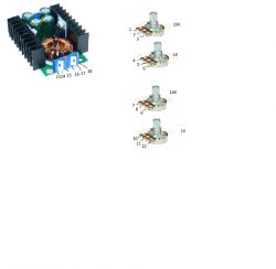
    I have Xl4016 converters and 2x 10k and 2x 1k potentiometers. The power supply I will use for this is 19v and 4.74A. I am asking for advice on how to connect the potentiometers so that the fine and coarse adjustment work.
    Thanks for the help
  • #87 17961870
    kj1
    Electrician specialist
    jendrus147 wrote:
    I am asking for advice on how to connect the potentiometers so that the fine and coarse adjustment work.

    See the front page of this topic
  • #88 17962131
    jendrus147
    Level 12  
    I would like to ask for help in connecting.

    Set - DC / DC converter 9A XL4016 and panel meter DSN-VC288, assembly, test
  • #89 17962292
    CMS
    Administrator of HydePark
    kj1 wrote:
    See the front page of this topic


    You have a drawing there. It couldn't be easier.
  • #90 17963122
    nasu
    Level 22  
    Maybe a multi-turn potentiometer can be used

Topic summary

The discussion revolves around the assembly and testing of a DC/DC converter based on the XL4016 chip, capable of outputting up to 9A and adjustable voltage from 1.2V to 35V, along with the DSN-VC288 panel meter for voltage and current readout. Users share experiences regarding circuit assembly, potential issues with reverse polarity connections, and methods for enhancing protection against such errors, including the use of Schottky diodes and relays. The conversation also touches on the practicality of using multiturn potentiometers for fine adjustments, the importance of proper grounding, and the challenges of using the converter for battery charging applications. Concerns about the reliability of components, particularly regarding counterfeit products, are also raised, emphasizing the need for quality assurance in electronic components.
Summary generated by the language model.
ADVERTISEMENT