logo elektroda
logo elektroda
X
logo elektroda

Set - DC / DC converter 9A XL4016 and panel meter DSN-VC288, assembly, test

TechEkspert 77316 166
ADVERTISEMENT
Treść została przetłumaczona polish » english Zobacz oryginalną wersję tematu
  • #121 19526404
    Dżyszla
    Level 42  
    You can always add a capacitor to the output for interference. In addition, the one from the topic will better withstand the load or work at high temperatures. The one in the attachment will work at the limit, so it might be easier to get over it.

    PS. In # 37 I showed the waveform on the oscilloscope.
  • ADVERTISEMENT
  • #122 19526419
    ArturAVS
    Moderator
    I've had this set since it showed up in the shop. Built into the workshop power supply, I did not notice any interference even when powering the radio devices.
  • #123 19526627
    serwis_sat
    Level 20  
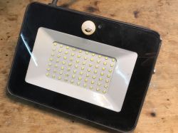
    The one in the photo has a "more interesting" range of elements, such as potentiometers or a power transistor.
  • #124 19526679
    TechEkspert
    Editor
    It looks linear, so the noise level in the output voltage may be lower than that of DC / DC, but the power loss will be higher.
  • #125 19526693
    E8600
    Level 41  
    serwis_sat wrote:
    I need a maximum of about 24V, 2.5-3A and the smallest possible interference.

    For some specific application? Currently, there are much more interesting converter modules, but they are not linear and there will always be some noise at the output.
    Examples of converters:
    - ZK-4KX
    - XYS3580
  • #126 19529642
    badboy84
    Level 43  
    Colleagues, tell me where is the problem? I bought and soldered a multi-turn potentiometer, probably 10 rpm. From 0 it is ok, but after more or less 5 turns I have max voltage. I can go on shooting but it doesn't do anything. The potentiometer I bought is a 10K Bourns name if it has any meaning. Does this type have it or did I just buy the wrong one?
  • ADVERTISEMENT
  • #127 19529862
    serwis_sat
    Level 20  
    She worked for me for a short time (sows disruptions). The ATX power supply was more stable. It was connected to a 22V transformer, 50A bridge, 6800uF conductor. Now I'm waiting for a transistor kit.
  • #128 19529918
    CMS
    Administrator of HydePark
    badboy84 wrote:
    Colleagues, tell me where is the problem? I bought and soldered a multi-turn potentiometer, probably 10 rpm. From 0 it is ok, but after more or less 5 turns I have max voltage. I can go on shooting but it doesn't do anything. The potentiometer I bought is a 10K Bourns name if it has any meaning. Does this type have it or did I just buy the wrong one?


    Is it really a linear potentiometer? Position it halfway and measure the resistance between legs 1 and 2 and then legs 2 and 3. The results should be the same.
  • #129 19529931
    Dżyszla
    Level 42  
    The second thing - the potentiometer is there to be adjusted to the maximum operating voltage of the converter. If you supply it with, for example, 12V, the regulation will only be in the range of 0-12 and it will be done on a fragment of the potentiometer scale.
  • #130 19530003
    damian1115
    Level 37  
    Dżyszla wrote:
    The second thing - the potentiometer is there to be adjusted to the maximum operating voltage of the converter. If you supply it with, for example, 12V, the regulation will only be in the range of 0-12 and it will be done on a fragment of the potentiometer scale.

    I don't understand something here.
    It seemed to me that the potentiometer should cover the entire voltage range with all its revolutions, regardless of the supply voltage. And it has nothing to do with the voltage connected to the inverter.
    Unless I'm wrong.
  • #131 19530037
    kj1
    Electrician specialist
    damian1115 wrote:
    Unless I'm wrong.

    I think so.
    This is a "step-down" converter
  • ADVERTISEMENT
  • #132 19530048
    damian1115
    Level 37  
    In a word, for each voltage, you would have to choose a different potentiometer. That it would work in the full range of revolutions.
  • #133 19530065
    ArturAVS
    Moderator
    damian1115 wrote:
    In a word, for each voltage, you would have to choose a different potentiometer. That it would work in the full range of revolutions.

    None of these things! The converter (specifically this one) will not give you the output voltage higher than the one that powers it.

    damian1115 wrote:
    It seemed to me that the potentiometer should cover the entire voltage range with all its revolutions, regardless of the supply voltage.

    You just felt bad. It would have to be a converter in SEPIC (Step up / Step down) topology that can both raise and lower the voltage, this is Step down, so you have a voltage always lower than the supply voltage at the output. I described a similar converter module that can be used as a programmed power supply / charger; https://www.elektroda.pl/rtvforum/topic3800804.html

    I have had the one from the online shop, along with the panel meter, built into the power supply that I use as a charger. The supply voltage is 23.9VDC, which "sits" up to 22.5VDC under load. The adjustment range is from 0 to 20.9VDC at the output, the "top" of the setting ends at about 3/4 of the voltage adjustment potentiometer setting. Connecting a voltage of about 35VDC to the power supply from a second power supply gives a range of 0-30V in the full range of the potentiometer adjustment (I have not tested higher voltages).
  • #134 19530094
    Justyniunia
    Level 36  
    I wrote about it on page 2 of this topic.
    For me, the max range ended earlier in relation to the potentiometer setting.
  • #135 19530113
    ArturAVS
    Moderator
    Justyniunia wrote:
    For me, the max range ended earlier in relation to the potentiometer setting.

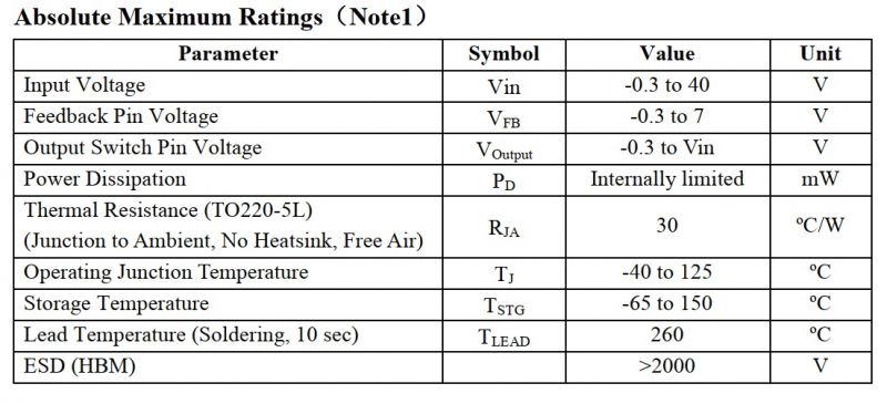
    To take full advantage of the regulation range, this converter should be powered from a "rigid" 32-33VDC source. Then there is a full range of adjustments. In the case of an ordinary transformer, it may not work (large voltage fluctuations behind the bridge depending on the load), but the use of a switching power supply, e.g. 24VDC / 10A with an additional potentiometer to set the Uwy (most allow for 22-27V regulation, so it may require modification) and set to 32VDC will allow you to enjoy the full range of adjustments. Initial voltage stabilization is required in order not to exceed the AMR (Absolute Maximum Ratings) of the manufacturer XL4016;

    Set - DC / DC converter 9A XL4016 and panel meter DSN-VC288, assembly, test
  • #136 19530166
    badboy84
    Level 43  
    CMS wrote:
    ...

    Is it really a linear potentiometer? Position it halfway and measure the resistance between legs 1 and 2 and then legs 2 and 3. The results should be the same.


    I guess so. With a different connection of the potentiometer, I got the effect that by half the voltage increased to max and then turning clockwise to the maximum, the voltage again began to decrease as if I turned left to 0.

    I do not know if I can provide the link, but I have a potentiometer.
    https://telmal.com/pototykiometer-wieloobrotowy-3590S-bourns-10k

    I will measure tonight.
  • #137 19530530
    CMS
    Administrator of HydePark
    badboy84 wrote:

    I guess so.


    CMS wrote:
    Position it halfway and measure the resistance between legs 1 and 2 and then legs 2 and 3.


    If you did, you'd be sure.

    But it doesn't matter anymore, because the matter has been clarified.
  • #138 19541778
    coperfild
    Level 35  
    Hello, gentlemen, or the XL 4016 may be damaged so that there is no current regulation, the voltage regulation works normally. I changed everything in this track and all the time max.
  • #139 19541865
    ArturAVS
    Moderator
    coperfild wrote:
    if the XL 4016 can break so that there is no current regulation, voltage regulation works normally.

    Not. You must have something else damaged in the control circuit, and in fact in the current limiter circuit.
  • #140 19686165
    kochar
    Level 9  
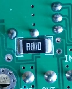
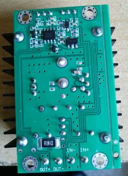
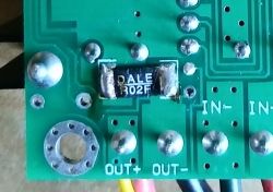
    I have a smd resistor R010 in this converter and I have a question, can I replace it with a regular resistor, and how?
    Set - DC / DC converter 9A XL4016 and panel meter DSN-VC288, assembly, test Set - DC / DC converter 9A XL4016 and panel meter DSN-VC288, assembly, test
  • #141 19686179
    ArturAVS
    Moderator
    kochar wrote:
    smd resistor R010


    R010 = 0.010? and power of at least 3-5W.
  • #142 19687804
    Olkus
    Level 32  
    It is a pity that this converter is not in the shop, will it appear again?

    Regards,
    AND.
  • #143 19687806
    ArturAVS
    Moderator
    Olkus wrote:
    Will there be yet?

    Nobody really knows ... My kit from the shop has been working almost flawlessly in one of the workshop power supplies since the moment of purchase. No failure because I had to replace the meter, some overvoltage during the games went after the power supply (or HF) and the voltage stabilizer burned a hole in the PCB.
  • ADVERTISEMENT
  • #144 19687837
    kochar
    Level 9  
    Set - DC / DC converter 9A XL4016 and panel meter DSN-VC288, assembly, test

    Due to the lack of lacquer, this original resistor R010 = 0.010? I replaced R020F = 0.020 ohms and the inverter came to life only, I do not know for how long?
  • #145 19687846
    ArturAVS
    Moderator
    kochar wrote:
    Due to the lack of lacquer, this original resistor R010 = 0.010? I replaced R020F = 0.020 ohms and the inverter came to life only, I do not know for how long?

    This resistor acts as a measuring shunt for the current limiter, setting up with a "crossroads" :D .
  • #146 19687885
    krzysiek_krm
    Level 40  
    kochar wrote:
    Due to the lack of lacquer, this original resistor R010 = 0.010? I replaced R020F = 0.020 ohms and the inverter came to life only, I do not know for how long?

    Put the second "on the pile" and you will have 0.01 ? equivalent resistance.
  • #147 19687947
    kochar
    Level 9  
    The problem is that I don't have it, so far it works and if I get something, I will improve it.
  • #148 19688277
    Olkus
    Level 32  
    ArturAVS wrote:
    Nobody really knows ... My kit from the shop has been working almost flawlessly in one of the workshop power supplies since the moment of purchase. No failure because I had to replace the meter, some overvoltage during the games went after the power supply (or HF) and the voltage stabilizer burned a hole in the PCB.


    It's a pity, this inverter and the meter are pretty cool.
    Unfortunately, these meters usually do not have any protection and it is easy to damage :(

    Regards,
    AND.
  • #149 19688776
    TechEkspert
    Editor
    Olkus wrote:
    It is a pity that this converter is not in the shop, will it appear again?

    Regards,
    AND.


    @gulson is there a chance for the inverters to return to the shop?
  • #150 19694910
    gulson
    System Administrator
    We should take new converters for testing and see if we can continue with the XL4016. However, there will be no converters by the end of the year.

Topic summary

The discussion revolves around the assembly and testing of a DC/DC converter based on the XL4016 chip, capable of outputting up to 9A and adjustable voltage from 1.2V to 35V, along with the DSN-VC288 panel meter for voltage and current readout. Users share experiences regarding circuit assembly, potential issues with reverse polarity connections, and methods for enhancing protection against such errors, including the use of Schottky diodes and relays. The conversation also touches on the practicality of using multiturn potentiometers for fine adjustments, the importance of proper grounding, and the challenges of using the converter for battery charging applications. Concerns about the reliability of components, particularly regarding counterfeit products, are also raised, emphasizing the need for quality assurance in electronic components.
Summary generated by the language model.
ADVERTISEMENT