logo elektroda
logo elektroda
X
logo elektroda

[BK7231N] [CB3S] [AHT20] TH01 Generic Temperature and Humidity Sensor Teardown

anthonythomas 33780 129
ADVERTISEMENT
  • #31 20628188
    grericht
    Level 6  
    I read these articles. I did not have two left hands, but I did not study electric-technic. So I have big problems to understand all of what is written, and I don't know what is really useful if I can't understand everything. I just want it to work.

    I now have:
    1. Cut the RX and TX traces at the Tuya MCU.
    2. Flashed actual BK7231N bin with Windows flasher (had many problems but got it flashed on 2 different devices).
    3. Resoldered the cut RX and TX traces at the Tuya MCU.
    Did not work: Powered the device (TH01 from this thread). First, I tried to power it with the battery pins, but the access point WLAN goes on and off all the time, so I can't get a stable connection to the access point - I think the reason is the battery saver or Tuya MCU?
    4. Then I powered the CB3S platine with 3.3V, and I got a stable connection.
    5. I did standard Wi-Fi settings and MQTT and restarted. TH01 is now in my home network. Sometimes it restarts. Is this normal?
    6. I copied this line "backlog startDriver tuyaMCU; startDriver tmSensor; linkTuyaMCUOutputToChannel 1 val 1; setChannelType 1 temperature_div10; linkTuyaMCUOutputToChannel 2 val 2; setChannelType 2 Humidity;linkTuyaMCUOutputToChannel 3 val 3; setChannelType 3 ReadOnly;" in the start command.
    7. Restarted.
    Trying to power it with the battery will not work. Where should I connect the + and -?
  • ADVERTISEMENT
  • #32 20628348
    DeDaMrAz
    Level 19  
    grericht wrote:

    Ok. Will try this next.

    I now have reached 2 different Tuya thermo/hygrometers with Open Beken flashed.
    1 I have resoldered the cut traces and on the other I didn't up to now.
    When I power the devices there is the Open Beken net, but on both I only get a short connection and can't reach 192.168.4.1. Connection will be lost very shortly.
    Is this because of the energy-saving mode of these devices?
    Did I have to resolder both?
    How can I get the configuration on the devices?


    @p.kaczmarek2 this looks to me like the light module, it needs a configuration otherwise the tuyaMCU will shut down - no heartbeat maybe?

    My solution for this was to power on the device (WiFi module) externally, configure everything then power it on batteries.
  • #33 20629135
    grericht
    Level 6  
    after configuring wlan settings i have some problems with configuration.
    i powered directly the cb3s platine

    first time i try to search in web app (config/Pick a device from the dropdown) for the correct device an found "Tuya TuyaMCU TH01 ...". -> copy device settings ->
    nothing changed but command: "backlog startDriver tuyaMCU; startDriver tmSensor; linkTuyaMCUOutputToChannel 1 val 1; setChannelType 1 temperature_div10; linkTuyaMCUOutputToChannel 2 val 2; setChannelType 2 Humidity;linkTuyaMCUOutputToChannel 3 val 3; setChannelType 3 ReadOnly;" ->
    save pins
    power off/on -> no change?! why?!

    when i use the "normal" interface option "config"/change startup command text it seems to be to long. i can copy and paste. all is pasted.
    after saving it is cuted and filed:
    original: backlog startDriver tuyaMCU; startDriver tmSensor; linkTuyaMCUOutputToChannel 1 val 1; setChannelType 1 temperature_div10; linkTuyaMCUOutputToChannel 2 val 2; setChannelType 2 Humidity;linkTuyaMCUOutputToChannel 3 val 3; setChannelType 3 ReadOnly;
    after saving: backlog startDriver tuyaMCU; startDriver tmSensor; linkTuyaMCUOutputToChannel 1 val 1; setChannelType 1 temperature_div10; linkTuyaMCUOutputToChannel 2 val 2; setChannelType 2 Humidity;linkTuyaMCUOutputToCha<input type='hidden' name='startup_cmd' value='1'><br><input type=
    after rebooting i get an error in web app/config/curret device: Error: SyntaxError: JSON.parse: expected ',' or '}' after property value in object at line 1 column 535 of the JSON data

    i have to return to factory settings by web app
    what is the correct way to get the startup command working
  • ADVERTISEMENT
  • #34 20639691
    maxen0815
    Level 3  
    Hi, I'm struggling with the same device...
    After flashing and getting the config done, I don't get any useful data on any channel... all are set to 0

    [BK7231N] [CB3S] [AHT20] TH01 Generic Temperature and Humidity Sensor Teardown

    Any idea where this effect is coming from?
  • #35 20639749
    p.kaczmarek2
    Moderator Smart Home
    Hello, it seems that no drivers are running. What is your current GPIO configuration on the panel?
    Helpful post? Buy me a coffee.
  • #36 20639863
    maxen0815
    Level 3  

    To be honest, I did not change the GPIO configuration since I expected the RX/TX communication with the MCU to be working "out of the box" %-)

    Is there a reference pinout I missed while reading the tutorials in the forum?!

    I referred to this post: https://www.elektroda.com/rtvforum/topic3947585-30.html#20427369 asking for the pin-setting as well and got the response "Just to get the temperature and humidity, the pin setting is not directly necessary."
  • #37 20640085
    p.kaczmarek2
    Moderator Smart Home

    If your device is TuyaMCU one, then maybe you need to copy the config from this post?
    https://www.elektroda.com/rtvforum/topic3947585-30.html#20383876
    Helpful post? Buy me a coffee.
  • #38 20640830
    maxen0815
    Level 3  

    With the mentioned Autoexec, it seems to load some drivers, but still no values visible...

    [BK7231N] [CB3S] [AHT20] TH01 Generic Temperature and Humidity Sensor Teardown
  • #39 20642216
    p.kaczmarek2
    Moderator Smart Home

    It is possible that you are approaching it in an incorrect way.

    It seems that you have a TuyaMCU device, a battery-powered one.

    Those devices are always controlled by the MCU. MCU only powers on the WiFi module when it wants to report data, WiFi module then initiates the UART conversation and MCU sends data to WiFi module. WiFi module then reports data to cloud and sends an "I'm finished" packet to MCU, which then turns off the WiFi module again.

    All that is done in order to preserve the batteries.

    If you are powering the WiFi module externally, then you won't get measurement results.

    So I will say this, the approach here is as follows:
    1. Get dpIDs data (or find existing matching config).
    2. Flash OBK.
    3. Power externally WiFi module.
    4. Setup OBK autoexec with dpIDs and channel types.
    5. Pair with Ha, do Home Assistant discovery.
    6. Disconnect external power for WiFi module.
    7. Put in batteries.
    8. Then it should start waking up for itself, for 30 seconds or so, every now and then and report data to your HA.

    Here is my topic about such a sensor:
    https://www.elektroda.com/rtvforum/topic3975583.html
    Helpful post? Buy me a coffee.
  • #40 20684096
    auntlydia
    Level 10  
    Hello everyone,

    thank you for this post, which was able to give me the basic information I needed in order to setup this sensor (TH01). With the aforementioned discussion about whether or not to sever some pins or desolder the WiFi module, I want to add some comments.
    I desoldered it for the reason that I was not able to get the device's created WiFi AP up and running long enough to enter configuration - simply because I was not patient enough. It is not necessary, don't do it, you don't need to. It was taking ages to desolder the battery pins, which was necessary in order not to melt the housing for the later-on desoldering of WiFi module with hot air, it's not worth it, I even damaged the housing while desoldering the battery terminals with my iron - a pain. Now, I would like to quickly give you the steps that worked for me.

    I flashed 4 sensors of the same type, and it worked the same for all of them.

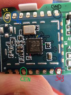
    1. have a look at the relevant pins:

    Close-up of a circuit board with labeled TX, RX, GND, CEN, and 3V3 pins.

    2. solder 5 indidivual wires to each of those. For TX / RX pins, you can also use the large round test pads on the motherboard, they are easier to access.

    3. connect 4 wires (3.3V, GND, TX, RX) to your USB-UART module, mind the 3.3V setting! make sure to connect TX ---> RX and RX ---> TX! If you want to use external 3.3V power source, connect the ground wire (-) of that source to BOTH our sensor AND USB-UART module.

    4. prepare Windows tool bk7231flasher: download current firmware (7231N!), I also recommend setting "Change OBK settings for flash write", this way you can already enter your WiFi credentials and mqtt data. Also, here you can already set the flags (I only used flag 10) and enter the startup code that is required for this module

    [backlog startDriver tuyaMCU; startDriver tmSensor; linkTuyaMCUOutputToChannel 1 val 1; setChannelType 1 temperature_div10; linkTuyaMCUOutputToChannel 2 val 2; setChannelType 2 Humidity;linkTuyaMCUOutputToChannel 3 val 3; setChannelType 3 ReadOnly;]

    so all that's left to do after flashing is to double check all the name settings and start Home Assistant discovery via the web interface.
    (--> If the startup command doesn't work later on, you need to enter it again via web interface. If there is no button to submit, it might be necessary to clear OBK config via web app command, after that you can re-enter new startup command)

    5. Now connect USB (and then external power if you use it) and wait a moment for it to show up in UART port. Also, give the module few seconds to power on. Don't forget to select "Automatically configure OBK on flash write" if you chose this setting in step 4

    6. Now make sure correct firmware is selected and then start process "Do backup and flash new", confirm dialogue and wait for log window to show waiting status. Now shortly (!) connect the end of CEN-wire to one of your GND terminals (just touch it and immediately release again), it will reset the device and reading/writing should start without any error messages. If you get any crucial error message, make sure to repeat step 5 and wait a minute before you start read/flash process. It worked for all my 4 sensors without exception.

    7. After successful flash, disconnect the module first. Then the important part in order to make the WiFi-connection work: connect only 3.3V and GND (doesn't matter where from) to the wires that are still attached, to power the device on again. Now, wait patiently! WiFi will pop up few times, after few minutes it will be stable! Either way, as AP if not preconfigured, or already in your router with new IP address. Then open web interface, finish configuration (HA discovery, names, startup command etc), and before you desolder the wires, pop in batteries and test if it still works. After disconnecting wires it will be annoying to acces the web interface - yet it is possible by either keeping the module's button pressed or press it down continuosly in 2 second intervals or so.

    Result in HA:

    Device info panel for Beken BK7231N and sensor status: battery, humidity, and temperature.

    (it was raining a lot here today, we can see it 😅 )

    Good luck!
  • #41 20716440
    dgel27
    Level 7  
    Hi, I also have same device, and load OpenBeken FW (Thanks for it!).
    Now, MCU's cycle power on is too short to collect and send data:

    Spoiler:

    Info:MAIN:Main_Init_Before_Delay
    Info:CFG:####### Boot Count 178 #######
    Warn:CFG:CFG_InitAndLoad: Correct config has been loaded with 7 changes count.
    Error:CMD:no file early.bat err -2
    Info:GEN:PIN_SetupPins pins have been set up.
    Info:MAIN:Main_Init_Before_Delay done
    Info:MAIN:Main_Init_Delay
    Info:MAIN:Main_Init_Delay done
    Info:MAIN:Main_Init_After_Delay
    Info:MAIN:Using SSID [************]
    Info:MAIN:Using Pass [***********]
    Info:MQTT:MQTT_RegisterCallback called for bT obk_C4CC000F4/ subT obk_C4CC000F4/+/set
    Info:MQTT:MQTT_RegisterCallback called for bT bekens/ subT bekens/+/set
    Info:MQTT:MQTT_RegisterCallback called for bT cmnd/obk_C4CC000F4/ subT cmnd/obk_C4CC000F4/+
    Info:MQTT:MQTT_RegisterCallback called for bT cmnd/bekens/ subT cmnd/bekens/+
    Info:MQTT:MQTT_RegisterCallback called for bT obk_C4CC000F4/ subT obk_C4CC000F4/+/get
    Info:CMD:CMD_StartScript: started autoexec.bat at the beginning
    Info:MAIN:Main_Init_After_Delay done
    Info:MAIN:Started tuyaMCU.
    Info:MAIN:Started tmSensor.
    Info:GEN:Channel 1 type changed to temperature_div10
    Info:GEN:Channel 2 type changed to Humidity
    Info:GEN:Channel 3 type changed to ReadOnly
    Info:MAIN:Time 1, idle 276116/s, free 77120, MQTT 0(0), bWifi 0, secondsWithNoPing -1, socks 2/38
    Info:MAIN:Time 2, idle 191115/s, free 77120, MQTT 0(0), bWifi 0, secondsWithNoPing -1, socks 2/38
    Info:MAIN:Time 3, idle 189013/s, free 77120, MQTT 0(0), bWifi 0, secondsWithNoPing -1, socks 2/38
    Info:MAIN:Time 4, idle 190149/s, free 77120, MQTT 0(0), bWifi 0, secondsWithNoPing -1, socks 2/38
    Info:TuyaMCU:TUYAMCU received: 55 AA 00 01 00 24 7B 22 70 22 3A 22 6C 66 33 36 79 35 6E 77 62 38 6A 6B 78 77 67 67 22 2C 22 76 22 3A 22 31 2E 30 2E 30 22 7D 99
    Info:TuyaMCU:TuyaMCU_ProcessIncoming[ver=0]: processing command 1 (QueryProductInformation) with 43 bytes
    Info:TuyaMCU:TuyaMCU_ParseQueryProductInformation: received {"p":"lf36y5nwb8jkxwgg","v":"1.0.0"}
    Info:MAIN:Time 5, idle 191246/s, free 77120, MQTT 0(0), bWifi 0, secondsWithNoPing -1, socks 2/38
    Info:MAIN:ssid:******** key:********
    Info:MAIN:Time 6, idle 175499/s, free 71856, MQTT 0(0), bWifi 0, secondsWithNoPing -1, socks 2/38
    Info:MAIN:Boot complete time reached (5 seconds)
    Info:CFG:####### Set Boot Complete #######
    Info:MAIN:Time 7, idle 184013/s, free 71608, MQTT 0(0), bWifi 0, secondsWithNoPing -1, socks 2/38
    Info:MAIN:Time 8, idle 84901/s, free 71592, MQTT 0(0), bWifi 0, secondsWithNoPing -1, socks 2/38
    Info:MAIN:Time 9, idle 0/s, free 71592, MQTT 0(0), bWifi 0, secondsWithNoPing -1, socks 2/38
    Info:MAIN:Time 10, idle 0/s, free 71592, MQTT 0(0), bWifi 0, secondsWithNoPing -1, socks 2/38
    Info:GEN:dhcp=0 ip=0.0.0.0 gate=0.0.0.0 mask=0.0.0.0 mac=50:8b:b9:4f:bc:fc
    Info:GEN:sta: 0, softap: 0, b/g/n
    Info:MAIN:Main_OnWiFiStatusChange - WIFI_STA_CONNECTING - 1
    Info:MAIN:Main_OnWiFiStatusChange - WIFI_STA_CONNECTED - 4
    Info:MAIN:Main_OnWiFiStatusChange - WIFI_STA_CONNECTED - 4
    Info:MAIN:Time 11, idle 90880/s, free 71952, MQTT 0(0), bWifi 1, secondsWithNoPing -1, socks 2/38
    Info:TuyaMCU:TUYAMCU received: 55 AA 00 02 00 00 01
    Info:TuyaMCU:TuyaMCU_ProcessIncoming[ver=0]: processing command 2 (MCUconf) with 7 bytes
    Info:TuyaMCU:TuyaMCU_ProcessIncoming: TUYA_CMD_MCU_CONF, TODO!
    Info:MAIN:Time 12, idle 203976/s, free 71992, MQTT 0(0), bWifi 1, secondsWithNoPing -1, socks 2/38
    Info:MQTT:mqtt_userName homeassistant
    mqtt_pass
    mqtt_clientID obk_C4CC000F4
    mqtt_host 192.168.1.22:1883
    Info:MAIN:Time 13, idle 190063/s, free 71904, MQTT 0(1), bWifi 1, secondsWithNoPing -1, socks 2/38
    Info:MQTT:mqtt_connection_cb: Successfully connected
    Info:MQTT:mqtt_subscribed to obk_C4CC000F4/+/set
    Info:MQTT:mqtt_subscribed to bekens/+/set
    Info:MQTT:mqtt_subscribed to cmnd/obk_C4CC000F4/+
    Info:MQTT:mqtt_subscribed to cmnd/bekens/+
    Info:MQTT:mqtt_subscribed to obk_C4CC000F4/+/get
    Info:MAIN:Time 14, idle 182216/s, free 71904, MQTT 1(1), bWifi 1, secondsWithNoPing -1, socks 2/38


    After this, MCU disconnect ground from the module. It is possible to make easy modification: bypass ground from the module (pin 9 on CB3S) to BAT- contact, use tuyaMCU driver and try to use FW deep sleep mode.
  • Helpful post
    #42 20768091
    DeDaMrAz
    Level 19  

    @dgel27

    Go to config, enable WiFi quick connect (flag 37). Also, decrease "Uptime seconds required to mark boot as ok:" from 5 to 3. You can also set up a static IP address for your device, which will help it boot faster and connect to your WiFi faster. This way, the timeout TuyaMCU is imposing will be enough, and your values/states will be reported.

    Hope this helps, and sorry for the late response.
  • ADVERTISEMENT
  • #44 20845229
    emrecetinkaya86
    Level 4  

    Hi,

    I don’t get any battery state. Is it not a feature of the device or am I missing something?

    Thanks
  • #45 20845231
    p.kaczmarek2
    Moderator Smart Home
    What is your device configuration? You will not get battery state entry unless you configure it
    Helpful post? Buy me a coffee.
  • ADVERTISEMENT
  • #46 20845669
    emrecetinkaya86
    Level 4  
    Hi,

    I just added those to startup commands, do i need to add anything for battery?:

    backlog startDriver tuyaMCU; startDriver tmSensor; linkTuyaMCUOutputToChannel 1 val 1; setChannelType 1 temperature_div10; linkTuyaMCUOutputToChannel 2 val 2; setChannelType 2 Humidity;linkTuyaMCUOutputToChannel 3 val 3; setChannelType 3 ReadOnly;

    Kind regards
  • #47 20845707
    p.kaczmarek2
    Moderator Smart Home
    So channel 3 is battery level? As in Low-Mid-High?
    So change:
    
    setChannelType 3 ReadOnly;
    

    To:
    
    setChannelType 3 LowMidHigh;
    

    See channel type docs at:
    https://github.com/openshwprojects/OpenBK7231T_App/blob/main/docs/channelTypes.md
    Helpful post? Buy me a coffee.
  • #48 20845783
    emrecetinkaya86
    Level 4  
    Ok i will. Thank you very much!
  • #49 20845795
    p.kaczmarek2
    Moderator Smart Home
    Keep in mind that you need to redo HASS discovery after changing the channel type.
    Helpful post? Buy me a coffee.
  • #50 20845859
    emrecetinkaya86
    Level 4  

    I did and also HA discovery. The 3rd channel's value is either 0, 1, or 2. I think it's equal to low-mid-high.
  • #51 20873676
    divadiow
    Level 34  
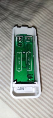
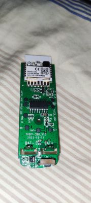
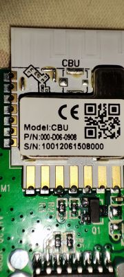
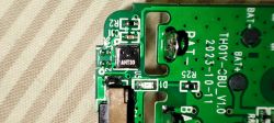
    I've just bought two of these and my variants are CBU module and AHT30 sensor.

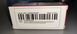
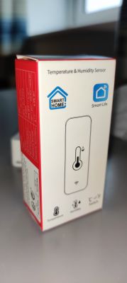
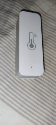
    I see no AHT30 search results yet on elektroda. I am away and cannot flash at the moment, but has anyone played with this type? Smart Life temperature and humidity sensor packaging with barcode. Smart Life temperature and humidity sensor packaging. External view of the TH01 temperature and humidity sensor in a white casing. Temperature and humidity sensor case without batteries on a fabric background. PCB of temperature and humidity sensor with CBU module. Close-up of a sensor PCB with the CBU module. Close-up of a PCB with AHT30 component and markings TH01Y-CBU_V1.0.

    My initial searching has found no mention of AHT30 on Aosong site. I've unsuccessfully tried to guess the URL of the datasheet, using a modified file name of the AHT20 pdf and URL.
  • #53 20904677
    sevastianovv
    Level 5  

    Good afternoon. Tell me, data is sent to MQTT 2 times. How to fix it?
  • #54 20904822
    p.kaczmarek2
    Moderator Smart Home
    Why is it a problem? Which device config?
    Helpful post? Buy me a coffee.
  • #55 20904927
    sevastianovv
    Level 5  
    
    startDriver TuyaMCU
    startDriver tmSensor
    
    // may be needed, depends on device, some also use 9600
    tuyaMCU_setBaudRate 115200
    
    // dpID 1 is tempererature div 10
    setChannelType 1 temperature_div10
    linkTuyaMCUOutputToChannel 1 val 1
    // dpID 2 is % humidity
    setChannelType 2 Humidity
    linkTuyaMCUOutputToChannel 2 val 2
    // dpID 3 is battery state - low(0), mid(1) and high(2)
    linkTuyaMCUOutputToChannel 3 enum 3
    setChannelType 3 ReadOnly
    setChannelLabel 3 Battery
    //
    // setup dpCache - temperature interval
    //
    // Show textfield for that
    setChannelType 5 TextField
    // setup display name
    setChannelLabel 5 Temperature Interval
    // Make value persistant (stored between reboots), 
    // start value -1 means "remember last"
    SetStartValue 5 -1
    // set default value if not set
    if $CH5==0 then setChannel 5 1
    // link dpID 17 to channel 5, the type is val, extra '1' means that its dpCache variable
    linkTuyaMCUOutputToChannel 17 val 5 60
    
    setChannelType 6 TextField
    setChannelLabel 6 Humidity Interval
    SetStartValue 6 -1
    if $CH6==0 then setChannel 6 1
    linkTuyaMCUOutputToChannel 18 val 6 60


    12:35:37 917		BK7231N_8587000B2/6/get	0.000000
    12:35:36 931		BK7231N_8587000B2/5/get	0.000000
    12:35:35 927		BK7231N_8587000B2/3/get	1.000000
    12:35:34 934		BK7231N_8587000B2/2/get	20.000000
    12:35:33 922		BK7231N_8587000B2/1/get	26.200000
    12:35:32 925		BK7231N_8587000B2/ip	192.168.1.213
    12:35:31 937		BK7231N_8587000B2/freeheap	73024
    12:35:30 932		BK7231N_8587000B2/uptime	12
    12:35:29 935		BK7231N_8587000B2/rssi	-55
    12:35:28 935		BK7231N_8587000B2/sockets	2
    12:35:28 294		BK7231N_8587000B2/ssid	434343434
    12:35:27 734		BK7231N_8587000B2/3/get	1.000000
    12:35:27 526		BK7231N_8587000B2/2/get	20.000000
    12:35:27 310		BK7231N_8587000B2/1/get	26.200000
    12:35:26 951		BK7231N_8587000B2/mac	a0:92:08:89:87:89
    12:35:25 933		BK7231N_8587000B2/build	Build on Jan 4 2024 11:21:20 version 1.17.391
    12:35:24 935		BK7231N_8587000B2/host	obkN_8587000B2
    12:35:24 301		BK7231N_8587000B2/connected	online
    
  • #56 20905032
    p.kaczmarek2
    Moderator Smart Home
    This config looks ok. My only question would be now why do you think it's a problem? You can try disabling "broadcast self state on MQTT connect" if you really want to, but in my opinion, there is no problem with device broadcasting data twice.
    Helpful post? Buy me a coffee.
  • #57 20905557
    sevastianovv
    Level 5  

    good afternoon. Yes, I did it on your advice, thank you. there is another question in mqtt, the data comes BK7231N_AC4D000A3/1/get 27.000000 how to get rid of zeros and leave 27.00
  • #58 20910745
    Wen2024
    Level 7  

    [BK7231N] [CB3S] [AHT20] TH01 Generic Temperature and Humidity Sensor Teardown
    I tried to flash TH01 with bk7231flasher_1.1.6 like auntlydia and rickbronson did. I use external 3.3V power supply. I connect +3.3V to TH01, GND to TH01 GND and USB-UART ground, TH01 RX2 to USB-UART Tx and TH01 TX2 to Rx USB-UART. (See photo). I powered TH01 on and off or shorted TH01 CEN to ground. All without success. Always got: "Getting bus failed, will try again...". I changed USB-UART (CH340, FTDI). I tried different baud rates. Please help!
  • #59 20911136
    p.kaczmarek2
    Moderator Smart Home
    Did you cut the connection to MCU? Few posts above user described the procedure well.
    https://www.elektroda.com/rtvforum/topic3968377-30.html#20628188
    Helpful post? Buy me a coffee.
  • #60 20911152
    Wen2024
    Level 7  

    No, I didn't because of Aunt Lydia's post: "I desoldered it for the reason that I was not able to get the device's created WiFi AP up and running long enough to enter configuration - simply because I was not patient enough. It is not necessary, don't do it, you don't need to. It was taking ages to desolder the battery pins, which was necessary in order not to melt the housing..." and Rick Bronson's post: "I read all the posts and found that I DID NOT need to unsolder anything to do the UART flashing...."

Topic summary

The discussion revolves around the teardown and firmware flashing of the TH01 Generic Temperature and Humidity Sensor, specifically using OpenBK7231N firmware. Users share their experiences with flashing the device, configuring it for WiFi and MQTT, and troubleshooting issues related to data reporting and connectivity. Key points include the necessity of severing RX/TX connections to the MCU for successful flashing, configuring autoexec.bat for driver initialization, and addressing problems with data values being reported as zero. Users also discuss the impact of power supply configurations on device performance and the importance of correctly setting up MQTT for data transmission. Various solutions and configurations are proposed to enhance device functionality and battery life.
Summary generated by the language model.
ADVERTISEMENT