FAQ 
TL;DR: TuyaMCUAnalyzer helps decode 15+ Tuya UART packet cases; the core rule is "Both MCU and WiFI modules has to be powered." This FAQ is for OpenBeken and Tuya hackers who need dpID detection, safe UART sniffing, and RX/TX capture guidance. [#20625222]
Why it matters: Correct dpID decoding turns captured Tuya traffic into usable relay, dimmer, sensor, and energy-monitor channels.
| Option |
Specific use |
Thread value |
| One USB-to-UART adapter |
Capture one direction at a time |
RX line only, repeat for the other line |
| Two CH340 adapters |
Capture both UART directions |
One RX on MCU RX, one RX on MCU TX |
| CH342 adapter |
Dual capture with one USB device |
2 UARTs on one chip |
| RealTerm text capture |
File-based packet capture |
Hex with spaces |
Key insight: Do not guess dpIDs from the product type. Capture stock TuyaMCU traffic, compare values, then map the confirmed dpIDs into OpenBeken channels.
Quick Facts
- TuyaMCU uses UART between the WiFi module and a separate MCU; that MCU can handle relays, buttons, LCDs, sensors, and metering circuits. [#20528459]
- The safe capture setup powers the board from USB, not mains, with 5 V fed before the onboard 3.3 V regulator when present. [#20528459]
- Common TuyaMCU dpID clues include bool values 0/1 for relays and value ranges like 0–570 or 1–1000 for dimmers. [#20528459]
- Version 0.2 added dual UART capture with two USB dongles, plus file-opening and miscellaneous UI options. [#20562010]
- Version 0.5 added a datetime crash fix, realtime capture pause, and buttons such as “copy raw” and “copy decoded.” [#20729095]
What is TuyaMCU and how does it let a Tuya WiFi module communicate with a separate MCU over UART?
TuyaMCU is a UART protocol linking the Tuya WiFi module to a separate device MCU.
"TuyaMCU is a UART-based protocol that lets a WiFi module exchange commands and datapoints with an onboard microcontroller, while the MCU handles local hardware such as relays, buttons, LCDs, sensors, and measurement systems." The WiFi module often reports data to the network, while the MCU drives the product hardware.
[#20528459]
How do I capture TuyaMCU UART packets safely with a USB-to-UART adapter and RealTerm?
Capture TuyaMCU packets by powering the device from USB and logging UART as spaced hex in RealTerm. 1. Connect USB-to-UART ground and RX/TX, but keep 5 V disconnected first. 2. Start RealTerm capture in “hex with spaces” and write to a file. 3. Power the board from USB, perform one operation, stop capture, then repeat for the opposite UART direction. The thread explicitly says not to power from mains during this method.
[#20528459]
What are Tuya dpIDs and how can TuyaMCUAnalyzer help identify relay states, dimmer levels, voltage, current, or sensor values?
dpIDs are Tuya datapoint identifiers that label each reported variable inside TuyaMCU packets.
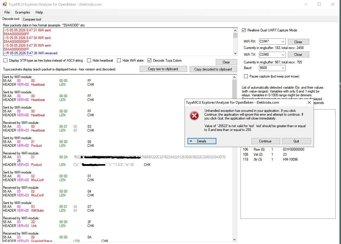
"dpID is a Tuya datapoint identifier that marks one device variable, such as a relay state, dimmer value, humidity reading, voltage, current, or raw measurement block, with a type and payload length." TuyaMCUAnalyzer lists detected dpIDs, types, lengths, and captured values. Bool dpID values 0/1 suggest relays. Dimmer values can appear from 0 to 570 during testing, with 1000 as a common full-scale target.
[#20528459]
Why should a TuyaMCU device stay on stock Tuya firmware and be paired to the cloud before sniffing packets?
Keep stock Tuya firmware so the analyzer captures the original TuyaMCU transactions. The device should also be paired and connected to the cloud, showing WiFi state 0x04. That state gives the “full Tuya experience” and records complete TuyaMCU exchanges. If you replace firmware first, you can lose the original app-driven behavior needed to identify light sensors, presence values, or other dpIDs.
[#20625222]
How do I power both the WiFi module and the TuyaMCU safely while capturing UART data without using mains power?
Power both chips from a safe low-voltage source, not directly from mains. Use 3.3 V on the WiFi module’s 3.3 V pin, or feed 5 V into the input of an onboard AMS1117-3.3 regulator. That regulator then supplies stable 3.3 V to the WiFi module. The separate MCU must also receive power, or no TuyaMCU communication will appear.
[#20625222]
What baud rates should I try when TuyaMCUAnalyzer shows no packets, and why are 9600 and 115200 commonly tested?
Try 9600 first, apply the baud change, then test 115200 if no packets appear. One troubleshooting case failed because the baud combobox changed to 9600 without pressing “Change.” The author then suggested trying the alternate baud rate, 115200. A later firmware backup showed a baud setting, supporting the chance that the device used TuyaMCU.
[#20630423]
How can I tell whether a Tuya device really uses TuyaMCU if I cannot identify a separate MCU on the PCB?
Check the PCB traces, power rails, and firmware evidence before assuming TuyaMCU. Use a multimeter to see where CBU RX and TX connect, and verify that a second module or MCU receives power. A 2 MB flash backup can reveal TuyaMCU baud settings. In the thread, a baud setting in flash gave “a fair chance” that the board used TuyaMCU.
[#20631789]
How do I use two CH340 USB-serial adapters, or a CH342 dual UART adapter, to capture both TuyaMCU RX and TX lines at the same time?
Connect only the RX input of each adapter to one UART direction. Use one CH340 RX on MCU RX and another CH340 RX on MCU TX, with a shared ground when safe. This listens to both directions without driving the bus. A CH342 can replace two CH340 boards because it provides 2 UARTs on one chip and one USB connection.
[#21835480]
CH340 vs CH342 — which is more convenient for dual UART TuyaMCU packet sniffing?
CH342 is more convenient for dual UART sniffing because it provides 2 UARTs through one USB device. Two CH340 adapters also work, but they occupy two USB connections and require matching two serial ports. The thread confirms the dual-CH340 wiring and recommends CH342 as a single-chip, single-USB alternative for convenience.
[#21835480]
What does it mean if a CH340 adapter shows 3.4 V or 5.2 V on its RX line, and how should I handle 3.3 V versus 5 V UART levels?
A voltage on the CH340 RX line can be normal, but level mismatch is the real danger. One user measured 3.4 V on a newer CH340 RX line and 5.2 V on an older one. The warning was specific: problems arise when attaching a 3.3 V UART to a 5 V device, or the reverse. Match UART logic levels before connecting.
[#21835641]
How can I determine whether a Tuya device power supply is isolated, and what is the difference between flyback and buck supplies for UART safety?
Identify the supply topology: flyback supplies have isolation, while buck supplies do not. This matters because a non-isolated buck design can reference the low-voltage UART section to mains. The thread gives the practical rule in one line: “Flybacks have isolation, and bucks do not.” If unsure, do not attach PC-grounded serial hardware.
[#20723628]
Why is it dangerous to connect a PC USB-to-UART adapter directly to a mains-powered Tuya device, and what kind of isolator should be used for sniffing?
A direct PC USB-to-UART link can be dangerous when the Tuya device is mains powered and not isolated. One warning states: “NO!!! DO NOT connect anything that is directly mains powered directly!!!” Use a communication isolator for UART sniffing, or power the board from an isolated low-voltage supply instead. The key risk is tying PC ground to a live-referenced circuit.
[#20632329]
How do I map detected TuyaMCU dpIDs to OpenBeken channels using commands like linkTuyaMCUOutputToChannel?
Map each confirmed dpID to an OpenBeken channel with its Tuya type and target channel number. Example: EDM-01AA-EU uses channel 1 as toggle and channel 2 as dimmer. The script links dpID 1 bool to channel 1, then dpID 2 val to channel 2. It also sets baud to 115200 and dimmer range to 1–1000.
[#20528459]
What changed in TuyaMCUAnalyzer versions 0.4 and 0.5, including heartbeat hiding, light color decoding, ASCII/HEX strings, pause, and copy buttons?
Version 0.4 improved filtering and decoding, while version 0.5 improved capture workflow and stability. Version 0.4 added heartbeat hiding, TuyaMCU light color decoding, ASCII or HEX string display, and a maximizable window. Version 0.5 fixed a crash on datetime packets, added realtime capture pause, and added buttons such as “copy raw” and “copy decoded.”
[#20729095]
How can I troubleshoot errors while retrieving data from a Tuya module in TuyaMCUAnalyzer?
Start with wiring, baud, power, and device-state checks before blaming the analyzer. Confirm 9600 and 115200 baud, press “Change” after selecting baud, and verify both WiFi module and MCU power. Keep stock Tuya firmware paired to cloud state 0x04 for complete traffic. If no packets appear, check RX/TX continuity with a multimeter and confirm the board really uses TuyaMCU.
[#20625222]
AI summary based on the discussion. May contain errors.