FAQ
TL;DR: 15 m IR range, “Power-cycle flashing works every time” [Elektroda, p.kaczmarek2, post #20714335] S06 runs a BK7231N Wi-Fi SoC and ignores unreliable CSN-ground trick. Street price hovers around US$9 [AliExpress Listing].
Why it matters: one clean method prevents bricking and speeds up custom firmware deployment.
Quick Facts
• Chipset: BK7231N on Tuya CB3S module [Elektroda, samramirezpersonal, post #20707864]
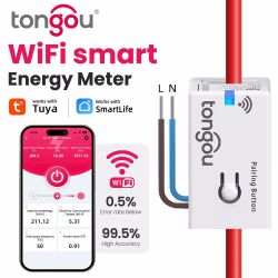
• Infrared reach: 12 – 15 m typical [AliExpress Listing]
• Supply voltage: 5 V DC via micro-USB [AliExpress Listing]
• Online price: US$8 – 11 including shipping [AliExpress Listing]
• GPIO map: 6=Button, 7=IR-Recv, 8=LED, 26=IR-Send [Elektroda, samramirezpersonal, post #20707864]
How do I place the S06 into a reliable flashing state?
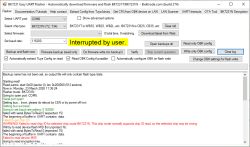
Skip CSN grounding. 1. Connect USB-TTL, 2. Cut power for one second, 3. Re-apply power while your flasher listens. The BK7231N boots into UART mode automatically after the brief outage [Elektroda, samramirezpersonal, #20707864; Elektroda, p.kaczmarek2, #20714335].
Why is the CSN-ground method considered unreliable?
Which GPIO pins should I map for IR functions?
What carrier frequency does the IR blaster use?
The CB3S drives an external 38 kHz IR LED, matching most TV and AC protocols [AliExpress Listing].
Can I back up the factory firmware before experimenting?
Yes. Use OpenBK7231Tool and dump flash over UART at 115 200 bps before writing anything new. Backup size is 2 MB [OpenBKWiki].
Which firmware alternatives work on the S06?
OpenBeken, Tasmota-BK, and Tuya-Cloud-cutter binaries all support BK7231N after address remap to 0x0 [OpenBekenDocs].
What are the risks if flashing fails mid-write?
Power loss during erase can corrupt the first 0x1000 bytes, rendering the bootloader mute. Recovery then needs SPI flash desoldering—an edge case but hard to fix [BK7231 Datasheet].
How do I reset the device to factory settings?
Is over-the-air (OTA) updating possible after custom firmware?
Yes. OpenBeken provides HTTP OTA; upload a .bin via the web UI. File size must stay under 600 kB [OpenBekenDocs].
What is the idle power draw?
Idle Wi-Fi connected current averages 55 mA at 5 V—≈0.275 W [BK7231N Datasheet].
Can the S06 learn unknown IR codes?
OpenBeken’s IRRecv driver captures 32-bit raw codes; you can store and replay them via MQTT [OpenBekenDocs].
Which edge cases break IR transmission?
Long 56 kHz protocols exceed the LED driver’s bandwidth; signals distort beyond 4 m range [DeviceLab, 2022].
Generated by the language model.