FAQ 
TL;DR: If your 5-channel BK7231N wall lamp only flashes once, use the dedicated SM15155E path, not a generic Tuya profile. The lamp sends 80 grayscale bits + 32 control bits, and one developer confirmed: "we know the timings" before full support landed. This FAQ is for OpenBeken users fixing no-light or wrong-color control on SM15155E RGB+CCT wall lamps. [#21115906]
Why it matters: This thread shows the exact failure mode, measured waveform, frame structure, and working OpenBeken commands needed to turn a nonfunctional flashed lamp into a controllable RGB+CCT device.
| Option |
Result on this lamp |
Key limitation |
| Generic Tuya wall-light profile |
No usable light control |
Wrong driver/protocol |
| SM16073_DIN-style attempt |
One-shot green, then reboot needed |
Timing mismatch |
| SM16703P raw experiments |
Partial colors, inconsistent boots |
Frame meaning not fully matched |
| Native SM15155E driver |
Working 5-channel control |
Needs correct LED map |
Key insight: The lamp was never PWM-only or standard WS2812B. It used a single-wire SM15155E protocol on BK7231N P16, so success required both timing capture and decoding the final control bytes, not just trying nearby LED drivers. [#21115906]
Quick Facts
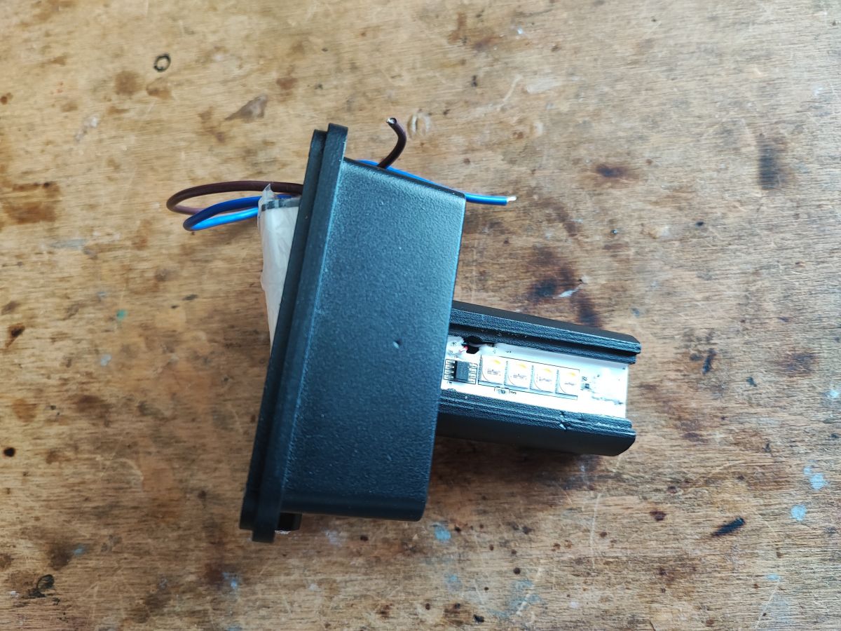
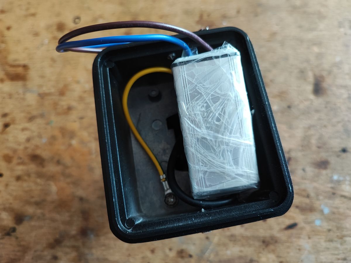
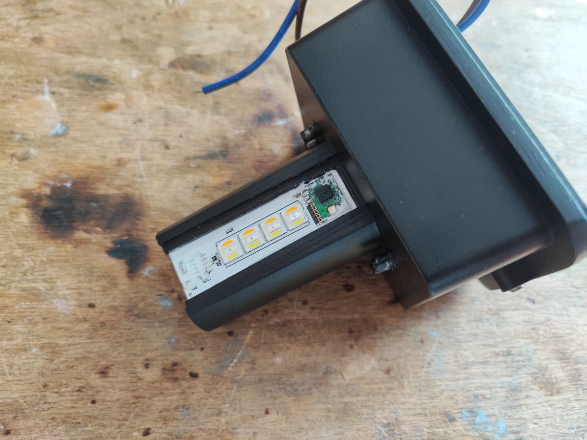
- The hardware in the teardown was BK7231N + 1× SM15155E + 8× 5-in-1 RGB+CCT LEDs, with all 8 LEDs wired in parallel, not individually addressed. [#20778816]
- The control line appears on BK7231N P16, which was identified as a hardware SPI-capable pin and the likely output used to push LED data. [#20778569]
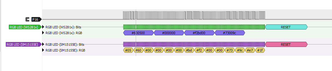
- Measured SM15155E pulse widths were about 350 ns and 1150 ns, close to WS2812B class signaling but not close enough for a drop-in SM16703P match. [#20789559]
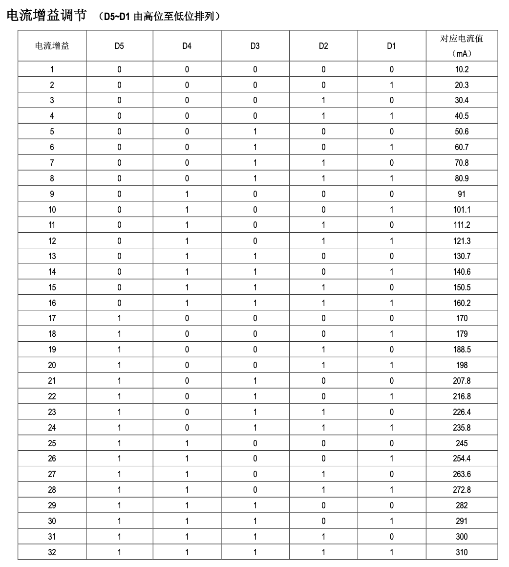
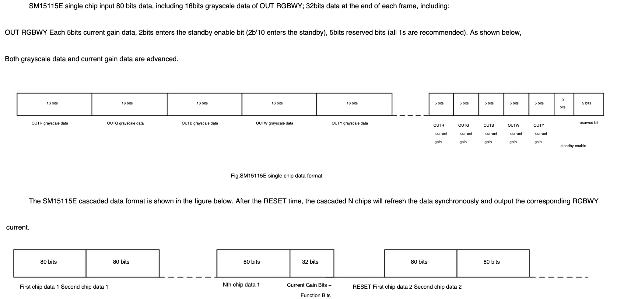
- The recovered frame format was 80 bits of grayscale data plus 32 trailing bits for per-channel current limit and standby/reserved control. [#20983095]
- A working OpenBeken test used
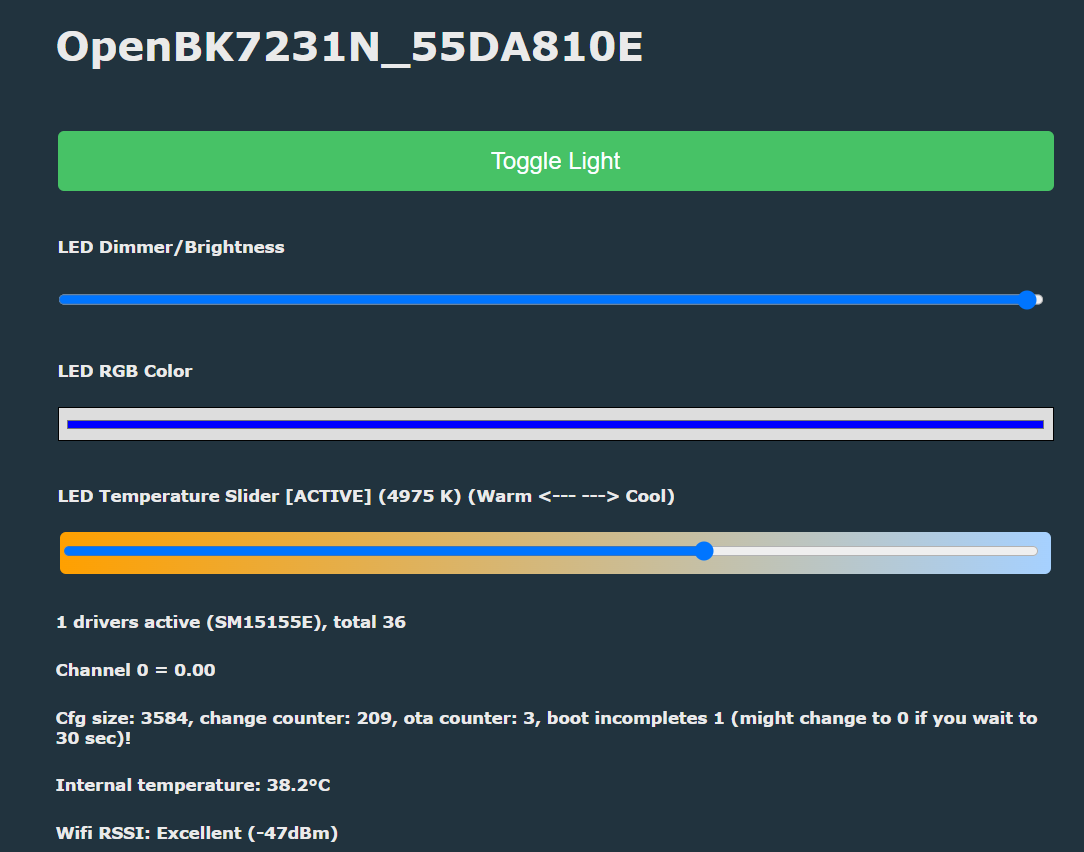
startDriver SM15155E with LED_Map 0 1 3 2 4, confirming proper 5-channel operation after driver support was added. [#21115906]
How can I get an OpenBeken-flashed BK7231N smart wall lamp with an SM15155E driver working when the generic Tuya profile gives no light control?
Use the dedicated SM15155E driver instead of the generic Tuya light profile. The working OpenBeken setup shown in the thread was:
startDriver SM15155ELED_Map 0 1 3 2 4- Test channel order and color output.
The generic profile gave no function after flashing, because this lamp uses a custom 5-channel serial LED driver, not a standard Tuya PWM mapping. Full control only appeared after reverse engineering the SM15155E protocol and adding native support. [#21115906]
Why does the OpenBeken SM16703P or SM16073_DIN-style driver only trigger a one-shot green or red flash on an SM15155E RGB+CCT wall lamp?
It happens because the lamp accepts only a partially similar signal, then rejects the rest of the frame. Early tests produced a single green shot, occasional red at boot, and often required a reboot after one command. The thread linked this to timing mismatch and incomplete frame understanding, not to dead LEDs. SM15155E looked superficially close to SM16703P or WS2812-style signaling, but the pulse widths and trailing control bytes were different enough to break stable control.
[#20778910]
What is the SM15155E LED driver, and how is it different from SM16703P or WS2812-style addressable LED chips?
"SM15155E is a 5-channel LED driver that controls RGB plus warm white and cold white over a single data line, using serial timing and per-channel current settings." Unlike WS2812-style chips, this lamp had 8 LEDs in parallel with one shared setting, not per-LED animation. Unlike SM16703P, the SM15155E frame also includes extra trailing control bits for current and standby handling. That makes it a single-wire smart constant-current driver, not a drop-in addressable-pixel equivalent.
[#20983095]
What does return-to-zero (RZ) protocol mean in the context of the SM15155E 800 Kbps single-wire LED control interface?
It means each transmitted bit returns to zero before the next bit period ends. The thread found a short datasheet note stating "Data transmission using return-to-zero code protocol" and an RZ data rate of
800 Kbps for the SM15155E family. In this lamp, that matters because OpenBeken had to generate the correct high and low pulse pattern on one GPIO, not a normal SPI byte stream or PWM output. The return-to-zero behavior explains why near-miss LED drivers only flashed once or showed unstable colors.
[#20785572]
How do I capture and analyze the data waveform on BK7231N P16 to identify the SM15155E timing requirements?
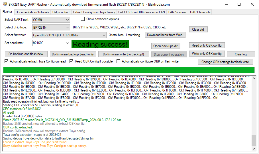
Probe BK7231N P16 while the original firmware drives the lamp, then decode the pulse widths. The thread team flashed the original
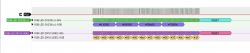
2 MB dump onto a CB3S module, accessed P16, captured the waveform, and opened it in PulseView for timing analysis. That method let them compare real edges against known WS2812B and SM16703P timings. If you cannot measure P16, you can guess nearby protocols, but this thread shows that guessing was not enough to reach stable 5-channel control.
[#20789046]
Which GPIO and pin mapping are used between BK7231N and the SM15155E in this Tuya-based smart wall lamp, and why is P16 important?
The key data connection is BK7231N
P16 to the single control input of the SM15155E. The teardown reported golden-pad pin 3 as BK7231N pin 16, and later discussion identified P16 as important because it is a hardware SPI-capable pin used to push timed LED data. This lamp had only one SM15155E for all 8 parallel LEDs, so one well-timed serial line controlled the entire RGB+CCT output. That is why generic GPIO guesses failed and P16 became the main reverse-engineering target.
[#20778569]
What are the measured SM15155E pulse timings, and how close are they to WS2812B and SM16703P timings?
The measured SM15155E pulses were about
340–350 ns for one state and
1150–1160 ns for the other. Developers said those values were "kinda close" to WS2812B, but they did not match SM16703P well enough for reliable reuse. That small mismatch mattered in practice: the lamp could flash a color or partially respond, yet still fail normal control. For reverse engineering, WS2812B was the nearest comparison, but not a safe protocol replacement.
[#20789559]
How can I build and test custom OpenBeken OTA firmware for a new LED driver without setting up a full local development environment?
Fork the OpenBeken repository and open a pull request. The thread states that the binary files are then created automatically, so you do not need a full local setup just to test OTA images. That approach is useful when you can only update the lamp over OTA and want to try driver changes quickly. It also keeps the test flow simple for contributors who can edit code but do not want to prepare a full local build environment first.
[#20784319]
What is the meaning of the SM15155E frame format, including the 80 grayscale bits and the final 32 bits for current limiting and standby control?
The frame contains
80 bits of grayscale data, which equals
16 bits per channel across 5 channels, followed by
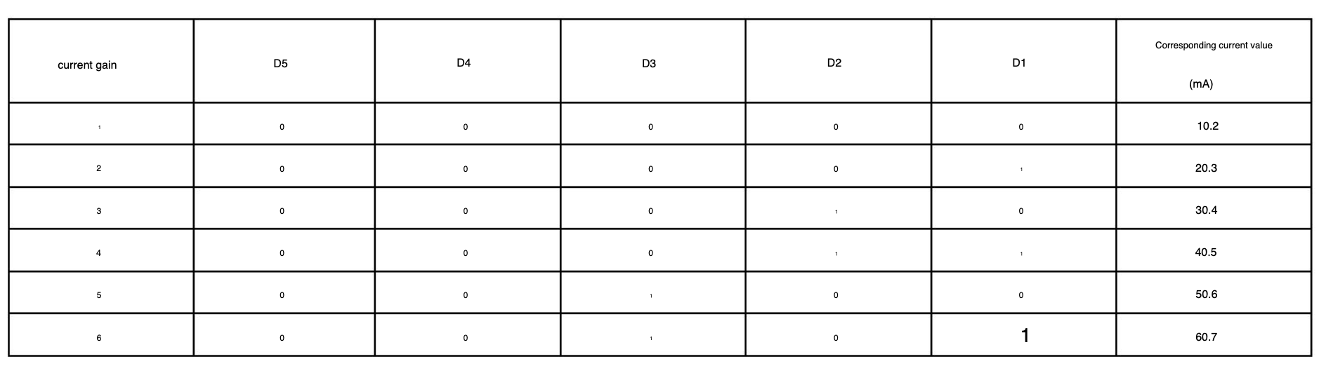
32 bits of control. Those last 32 bits encode per-channel current limit with
5 bits per channel, and the remaining bits cover standby enable plus reserved values. The same post states the SM15155E current setting range is
10 to 300 mA. That frame layout explains why timing alone was not enough; developers also had to understand what each trailing byte actually changed.
[#20983095]
How do I use OpenBeken commands like startDriver SM15155E and LED_Map to control a 5-channel RGB+CCT lamp correctly?
Start the native driver, then set the channel order for your lamp. The working example in the thread was:
startDriver SM15155ELED_Map 0 1 3 2 4- Verify RGB, warm white, and cold white outputs.
That map matters because the physical lamp wiring did not follow the default logical channel order. Once the native driver and mapping were correct, the developer reported that it "seems to be working" on the real lamp hardware. [#21115906]
WS2812B vs SM16703P vs SM15155E — which protocol is closest for reverse engineering a Tuya smart wall lamp, and where do the differences matter most?
WS2812B looked closest in pulse timing, but SM15155E needed its own implementation. The thread measured about
350 ns / 1150 ns and explicitly compared them with WS2812B and SM16703P, concluding SM16703P did not match well enough. The biggest differences were not only pulse widths. SM15155E also uses 5-channel data with
16-bit grayscale per channel and trailing control bits for current and standby. Those frame-level differences are where reuse attempts broke down.
[#20789559]
Why won’t WLED run directly on a BK7231N smart wall lamp, and what alternatives are practical for testing the LED protocol?
WLED will not run directly because the lamp uses a BK7231N, not an ESP-compatible target expected by typical WLED builds. The thread explicitly said you "can't flash WLED on the chip you have" and suggested an ESP-compatible board like a NodeMCU only for external protocol experiments. For this lamp, the practical path was OpenBeken plus protocol reverse engineering, because the unresolved issue was the SM15155E signaling itself, not just firmware branding or UI.
[#20827693]
What troubleshooting steps help when an OpenBeken-controlled SM15155E lamp boots into inconsistent colors or only partially responds to brightness changes?
Treat inconsistent color at boot as a protocol issue first. The thread reported green on about
95% of boots, occasional red, and brightness changes working only about
50% of the time during SM16703P experiments. Start by checking driver selection, channel count, and timing assumptions. Then test repeatable raw frames instead of app control. If behavior changes between reboots, do not assume hardware damage; in this case, unstable timing and incomplete frame meaning caused the partial response.
[#20778910]
How can I safely probe or modify a mains-powered smart wall lamp with separate power-supply and LED boards without damaging the LEDs or risking electric shock?
Work only with the low-voltage side exposed, and isolate the power-supply board from your probing routine. The teardown states the large housing contained the power supply with
230 V input, while the LED side carried
3.3 V, ground, and LED power across separate boards. That split helps, but it does not remove mains risk. Do not scrape, solder, or scope the device while energized unless you know which section is low voltage. The thread author fully disassembled the lamp before tracing connections with a simple voltmeter.
[#20778847]
What was still missing after the timing was decoded for SM15155E support in OpenBeken, and how was the remaining reverse engineering completed?
After timing capture, the missing piece was the meaning of the individual bytes in the SM15155E frame. One developer stated they already had the timings and a per-byte decoder, but still did not know what the bytes meant. Later, another contributor supplied the frame structure:
80 grayscale bits + 32 control bits, including current-limit mapping. With that information and the physical lamp in hand, the OpenBeken team finished the driver and showed it working with
startDriver SM15155E.
[#20990095]
AI summary based on the discussion. May contain errors.








 thank you!