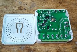
 .
.
Today we are taking a look inside a fairly new "smart switch" relay, dated 2023-10-05 on the PCB. As standard here, I will show its construction and change its firmware to make it free from the manufacturer's servers. The product itself from this topic resembles the already discussed ZN268131 , but is an updated version of it, among other things the old WB2S has been replaced by CB2S. The whole thing is available to buy in many shops and often under other names, so look at the pictures.
First - the packaging:
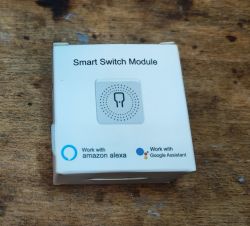
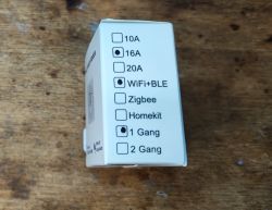 .
.
The set is quite poor:
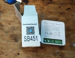
Instructions:


ADVERTISEMENT
Now the interior:
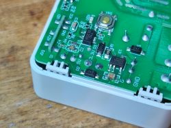
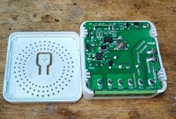
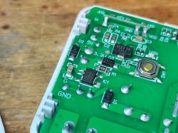 .
.
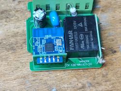
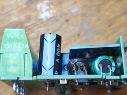
I don't see much change, in the linked older version of this product sat the AP8506, here is the BP2525 (classic), the rest similar.
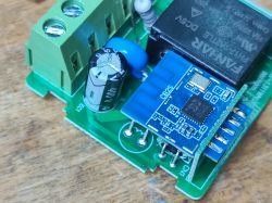
 .
.
Here we have the FH17-1A2TLE relay at 5V (it is powered directly from the BP2525), the CB2S itself is powered from a 3.3V LDO.
Of surprises, we also have a varistor present here - this is an exception, it is often overlooked.
SB451/DS-1311WN firmware change [/size] .
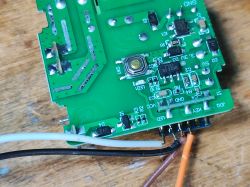
According to the flasher instructions - you need to solder the power supply, RX and TX:
https://github.com/openshwprojects/BK7231GUIFlashTool
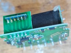
One would like to solder to the CB2S pad without removing it:
 .
.
But that won't work. You need to desolder the CB2S, flux and braid will help:
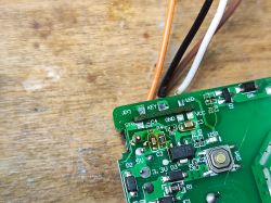 .
.
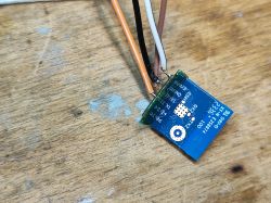
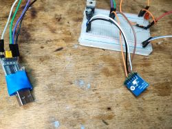
Here's my whole circuit, together also with the 3.3V LDO (I'm using TC1264-3.3V, but you can use any or even take 3.3V from NodeMCU or Arduino):
 .
.
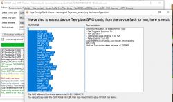
When reading the batch, my flasher correctly discovers the Tuya configuration:
 .
.
JSON Tuya:
Code: JSON
Verbal description:
Device seems to be using CB2S module, which is BK7231N chip.
- Relay (channel 1) on P8
- WiFi LED on P7
- TglChannelToggle (channel 1) on P26
- Pair/Toggle All Pin on P11
OBK template:
Code: JSON
A device configured in this way can also be paired with Home Assistant, details on our YT: https://www.youtube.com/playlist?list=PLzbXEc2ebpH0I8m_Cfbqv1MTlQuBKYvlx
Summary
The version in this topic is from 2023-10-05, the previously discussed version, ZN268131 , is from 2020-09-16. Rather not much has changed. The varistor is still present, the rest of the build is still almost identical, they've only swapped WB2S for CB2S, which is something I often encounter - BK7231N replaces BK7231T. In addition to this, since discussing the previous version I have added decoding of Tuya's JSON configuration so we no longer have to guess the GPIO configuration of this product manually. I can recommend its purchase.
PS: In OBK it's still worth enabling PowerSave on this chip (type PowerSave 1 in autoexec.bat), otherwise you'll probably damage the capacitor from the poor quality inverter from the middle quickly - see theme on repair .
Cool? Ranking DIY Helpful post? Buy me a coffee.


