logo elektroda
logo elektroda
X
logo elektroda

How to flash LN882H with open source Tasmota/Esphome style firmware - backup procedure included

p.kaczmarek2 42036 297
ADVERTISEMENT
  • ADVERTISEMENT
  • #272 21321492
    p.kaczmarek2
    Moderator Smart Home
    I didn't have time yet to check the recent posts, but I think it would be good to try to include such issues in the self tests, like I just did for UART buffer write:
    https://github.com/openshwprojects/OpenBK7231...mmit/a2f3b020686633c643ab8790875e00173bb9d354
    This allowed me to verify and check the great UART fix that @XJ_ submitted here:
    https://github.com/openshwprojects/OpenBK7231...mmit/e99ff0c1517af7c95e7c94c9211a5be1afe593c4
    Again, I didn't have yet time to investigate fully, but in general, I would try to slowly move towards having all features self-tested, just like I've did with UART, just to be sure that there are no strange errors like that...

    I will try to check this particular issue later, if my time allows it.

    PS: I did the same for startScript command: https://github.com/openshwprojects/OpenBK7231...mmit/9cd823cbdae04d10285777f62115504cfe7f0bd1
    Helpful post? Buy me a coffee.
  • ADVERTISEMENT
  • #273 21321519
    max4elektroda
    Level 20  
    p.kaczmarek2 wrote:
    , but I think it would be good to try to include such issues in the self tests,

    While I think that generally speaking self tests are a good idea, it will not help for platform specific bugs like the one I found here (if we don't talk about windows code bugs): the testing code will never reach code in this sections.
    And, how can I name it without sounding like I don't appreciate your valuable work?
    I just think this tests sometimes have a limited use case: if a test is written after a bug was corrected, it can only help if the code in question is changed incorrectly in the future.
    But usually this is exactly what you do before changing the code: test it. And if you fail because one special case was not in your scope, you will also have no test for this case and can only update the testing code after the bug was found and only prevent doing the same or similar error again.
    So it really depends on the type of code, if a test makes sense, and it will not help here.
  • #274 21321538
    io2345
    Level 7  
    >>20905518 This method is still the preferred way for the LN882H in 11/2024, right?
  • #275 21321552
    max4elektroda
    Level 20  
    io2345 wrote:
    This method

    That depends on which step you refer in detail: the post shows all steps needed very detailed. Depending on your device and skills you might e.g. be able to flash a module without desoldering it. But up to now there's no known way to initial flash the device without UART connection if that's your question.
  • #276 21321561
    divadiow
    Level 34  
    >>21321538

    a couple of things to note:
    - the LN882H_Flash_Dumper.py in the first post will create a 4mb file with a duplicate of the flash content. It'll take twice as long doing it. Updated script attached to read 2mb only. (maybe @p.kaczmarek2 wouldn't mind changing file in first post)
    ref: https://www.elektroda.com/rtvforum/topic4083817.html#21284784 - https://www.elektroda.com/rtvforum/topic4008545-90.html#20912035
    - there a Windows GUI flash option (no flash backup function) https://www.elektroda.com/rtvforum/topic4045532.html
  • ADVERTISEMENT
  • #277 21321611
    XJ_
    Level 11  
    max4elektroda wrote:
    I just think this tests sometimes have a limited use case: if a test is written after a bug was corrected, it can only help if the code in question is changed incorrectly in the future.

    I agree, it is necessary to consider where it makes sense. For example, for a code fix for RS232 or Flash, I would definitely leave the test, because new platforms are often added and new modules using them may have a different approach, e.g. from multiple threads at a time...
  • #278 21321650
    max4elektroda
    Level 20  
    I agree on this crucial parts.
    And it's also very usefull for "complex" code which relys on other code, so a change "somwhere else" can break a funktion.
    For the flashing code it depends - the common code could and should be tested if possible.
    You won't be able to do this on specific code like here: The ota flashing part is platform specific and distinguished by "#if defined <platform>" - invisible for the tests running on windows code.

    So for this it comes down to writing some own testing routine for that code, freeing it from all the hardware related stuff.

    And integrating this sort of tests into OBK tests would be strictly speaking not totally impossible - but almost: To make sure you test the actual code you would need to make a process to extract the code from the actual driver - change it to make it run on other platforms and remove the hardware part (e.g. with sed/grep/awk...) - very hard work. And if changes to the code are done, you will probably also need to change the "extraction code" accordingly. So, I think it's o.k. to call it impossible.
  • #279 21321789
    io2345
    Level 7  
    >>21321552 Thank you for answering. I already did flash a device some time ago (this one: https://www.elektroda.com/rtvforum/topic4036567.html). But now I can't reach it on the network any longer, although the device can be switched on/off using the hardware button. So I thought about reflashing it to see if it helps and was wondering, if the procedure is still the same.
  • #280 21321797
    p.kaczmarek2
    Moderator Smart Home
    Have you tried entering safe (AP) mode by doing quick 5 power off and on cycles?
    Helpful post? Buy me a coffee.
  • #281 21321837
    io2345
    Level 7  
    >>21321797 Never heard of that before. I will try. Device will restart as Access Point? Connect has to be done to 192.168.4.1 (as far as I remember), right?

    Hinzugefügt nach 1 [Stunden] 20 [Minuten]:

    It helped, I could connect to AP and after a reboot to the device. Might be worth mentioning, that I have two more identical devices running on FW 1.17.590 and 1.17.611. The device with the problem was OTA updated to 1.17.739 about a month ago. Maybe this version had a little problem. Will update now to the latest version.
  • #282 21332078
    p.kaczmarek2
    Moderator Smart Home
    max4elektroda wrote:

    I think I can merge it, but has anyone, @divadiow , someone else tested it as well just to be sure? If not, I must try to find my LN882H dev board...
    https://www.elektroda.com/rtvforum/topic4062695.html
    Helpful post? Buy me a coffee.
  • Helpful post
    #283 21332121
    divadiow
    Level 34  
    I've just UART flashed to 1441_merge_6d6a6086fa18 without issue then OTA in Firefox 132.0.2 to OpenLN882H_1.17.789_OTA.bin no problem.
  • #284 21332221
    p.kaczmarek2
    Moderator Smart Home
    Thank you for testing, merged.
    Helpful post? Buy me a coffee.
  • #287 21336923
    max4elektroda
    Level 20  
    Ah, they also found one of the bugs in OTA I recently discovered (after days of trying to isolate the problems with OTA and firefox):
    divadiow wrote:
    3. Fix the problem that the address may be calculated incorrectly during OTA file download and writing to flash

    Code snippet showing a fix changing the condition in an if statement.

    But they still don't see that data got from HTTP in rare cases could fill internal 4k buffer twice, which caused the main crashes during OTA.
  • #288 21336927
    XJ_
    Level 11  
    max4elektroda wrote:
    But they still don't see that data got from HTTP in rare cases could fill internal 4k buffer twice, which caused the main crashes during OTA.

    👍
  • ADVERTISEMENT
  • #289 21344542
    notzed
    Level 2  
    divadiow wrote:
    indeed, but why isn't it controllable? are RX/TX GPIOs always fixed high? The datasheet says FULLMUX, like other controllable GPIOs...


    I know it's late but after a day of frustration I found this out why today. The gpio input/output mode functions aren't clearing the alternative function bit so setting the port to input or output still leaves it operating as uart1 tx. I think this is a bug because it would mean you couldn't change from pwm to digital either. It's unclear why both uart0 and uart1 are both initialised and used for output (log + stdio?).
    Issue, a fix but no pr sorry: https://github.com/openshwprojects/OpenBK7231T_App/issues/1461

    Also for what it's worth the cozylife mini smart switch (at least) has an onboard 5V buck converter (BP2525) that can run on almost any ac/dc voltage (tested >=12v, >=9v probably works) which makes it a lot easier & safer to play with in-situ, not to mention useful for non-mains applications like irrigation.
  • #290 21344566
    poldim1
    Level 2  
    anyone know if there is a way to flash this from a mac/linux? I no longer have any PC's in the house...
  • #292 21360652
    jhatter55
    Level 3  
    Is it possible to enable the Wemo support for the LN882 like some of the other devices have? I can execute this command "backlog startDriver SSDP; startDriver Wemo" and it says OK but Alexa does not discover it. MQTT works fine. I use this feature with some BL602 devices I have and it works correctly. Great work supporting these other chips that aren't esp8266 and ESP32.
  • #293 21360764
    p.kaczmarek2
    Moderator Smart Home
    I think you can use online builds system to try compiling LN882H with WEMO driver:
    https://www.elektroda.com/rtvforum/topic4033833.html
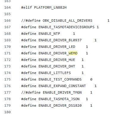
    Wait a second, I've just checked and it seems it's already enabled in the main tree:
    A code snippet configuring drivers for the LN882H platform.
    This means that you need to do some debugging.
    WEMO driver reqisters following handlers:
    Code: C / C++
    Log in, to see the code

    They are not present when driver is not run:
    Screenshot of a webpage at URL 192.168.0.163/setup.xml displaying Not found message.
    but once you start a driver, you can visit them easily:
    
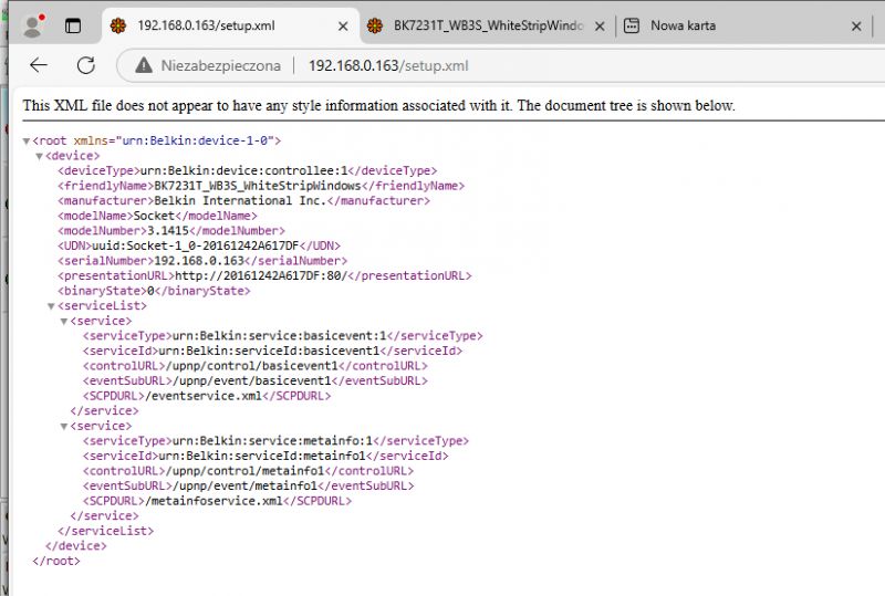
    http://192.168.0.163/setup.xml
    

    Screenshot showing an XML file with Belkin device data on a web page.
    So, my first question is - is the setup.xml working on your device?
    Helpful post? Buy me a coffee.
  • #294 21368504
    notzed
    Level 2  
    The code is a bit hard to navigate at first, but i'm getting familiar with it.

    I found the logs setup on UART0 (A8/A9) initialised sdk/OpenLN882H/components/utils/debug/log.c.
    And some 'AT console' on UART1 (A2/A3 marked TX/RX) at sdk/OpenLN882H/components/ln_at/ln_at.c, but it doesn't seem to do anything particularly useful.
    >>21345439
    max4elektroda wrote:
    But I don't know what happenes to all the logs if UART is not present...


    Configuring the pins as gpio properly seems to work as expected, the uart is running but doesn't go anywhere and the REST logs still work.

    Also for what it's worth after breaking off 2 boot pads I realised you don't need to solder anything on BOOT - it just needs to be grounded when for a short time when the power is applied which can be done with a piece of wire or test probe by hand. For the cozylife switch signal ground is available on S1, so you only need to solder to the 2 TX/RX pins and it all works in-place. I've been using 12V DC to power them via the mains input so you don't need a separate 3v3 power connection either.

    Added after 9 [minutes]:

    poldim1 wrote:
    anyone know if there is a way to flash this from a mac/linux? I no longer have any PC's in the house...


    I tried wine but the tool just hangs, I tried windows 10 in qemu but couldn't figure out the serial port config. In VirtualBox with a windows 10 install I could get the flash tool to work sometimes but it wasn't very reliable and I didn't want to install python so I didn't try reading or writing a whole flash. Its possible it could be made to work. I have a 'live usb' stick with a windows 10 install I created - first installed on qemu and then copied it to the flash stick. It's slow and tedious and updates take forever (disabling network helps) but it's enough to run the gui flash tool and it's been reliable.
  • #295 21371400
    jhatter55
    Level 3  
    >>21360764 Sorry for just getting back to this. Yes Setup.xml works on the device and it looks like yours minus the different device name and ip address but Alexa does not discover it like it did for the BL602 device.
    Screenshot of an XML file showing Belkin device data.
  • #296 21375129
    max4elektroda
    Level 20  
    notzed wrote:
    I found the logs setup on UART0 (A8/A9) initialised sdk/OpenLN882H/components/utils/debug/log.c.
    And some 'AT console' on UART1 (A2/A3 marked TX/RX) at sdk/OpenLN882H/components/ln_at/ln_at.c, but it doesn't seem to do anything particularly useful.
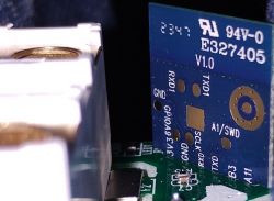
    There are several code fragments "initializing" UARTs, the question is, which ones are included.
    Just for reference: One UART is B8/B9 (not "A"), and in the documents it's sometimes referred as UART0 and sometimes as UART1
    E.g. here they are called "UART_RX1/UART_TX1" ...
    https://developer.tuya.com/en/docs/iot/WL2H-U-Module-Datasheet?id=Kbohlj8eg19u5
    And in the code (e.g. in "./project/OpenBeken/bsp/serial_hw.c") B8/B9 is UART0 and A2/A3 UART1 ...

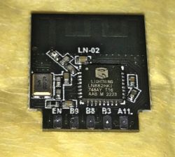
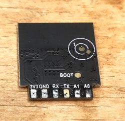
    To match it to the pins on the module:

    The two pins labeled RX/TX beneath GND on modules LN-02 and WL-2S are A2/A3 (UART0 on the Tuya page, UART1 in code)
    The two pins labeled RX1/TX1 on the back of WL-2S and labelled B8/B9 on the pins on the other side of VCC/GND on LN-02

    LN882H module with visible electronic components on a yellow background.LN882H module with visible pads and pin labels.Close-up of PCB with LN882H module and markings.

    Added after 1 [minutes]:

    notzed wrote:
    Configuring the pins as gpio properly seems to work as expected, the uart is running but doesn't go anywhere and the REST logs still work.

    Could you please explain a bit more detailed, what you did to configure this pins "properly"?
  • #298 21376302
    p.kaczmarek2
    Moderator Smart Home
    I've recently released a youtube guide for the same process:
    [Youtube] LN882H module pinout and setup for flashing - step by step video guide
    But this now means we have two LN882H flashing topics, so....

    I am closing this topic for now, please continue dicussion in YT guide topic.
    Helpful post? Buy me a coffee.

Topic summary

The discussion focuses on flashing the LN882H module with open-source firmware such as Tasmota or ESPHome, detailing the necessary hardware setup, including the use of a USB to UART converter and a reliable 3.3V power supply. Users share experiences with various programming tools, troubleshooting flashing errors, and the importance of using the correct baud rate (115200) for successful firmware uploads. The conversation also touches on issues related to power consumption, the implementation of power-saving modes, and the challenges faced when trying to reset configurations or passwords in the firmware. Additionally, there are mentions of specific devices using the LN882H chip and the need for community support in resolving technical issues.
Summary generated by the language model.
ADVERTISEMENT