logo elektroda
logo elektroda
X
logo elektroda

WBR2, WBR3, WBRU, W701-VA2-CG pinout, datasheet, flashing for Home Assistant

p.kaczmarek2 8085 76
ADVERTISEMENT
  • #31 21384224
    GAAD
    Level 17  
    How to copy the contents of the module? Because I don't see the option to read write memory to a file in Ameba.
  • ADVERTISEMENT
  • #32 21384825
    p.kaczmarek2
    Moderator Smart Home
    We're still this on our TODO list. For now, I'm testing with DS18B20:
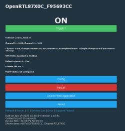
    OpenRTL87X0C user interface displaying sensor information and configuration options.
    Test setup:
    Test setup with DS18B20 sensor on a breadboard.
    Electronic test setup on a breadboard with DS18B20 sensor and DHT11 module.
    Breadboard with DS18B20 and DHT sensors placed next to each other, connected with colored wires.
    Close-up of a DS18B20 temperature sensor mounted on a breadboard with connected wires and a resistor.
    Helpful post? Buy me a coffee.
  • #33 21390033
    nemetila
    Level 5  
    I have used your guide on a Gosund SP1 Power Monitoring(BL097) Plug with the CUCO-Z0-R-V1.2. FR module(RTL8710CF chip) and it's working! To enter download mode: connect the RX and the IO0 pins to 3.3V. The two LEDs, the button, the relay are working. The BL097 seems working, but it requires calibration.

    == Rtl8710c IoT Platform ==
    Chip VID: 5, Ver: 3
    ROM Version: v3.0
    Test Mode: boot_cfg1=0x20
    Download Image over UART2[tx=16,rx=15] baud=115200
  • #34 21390039
    p.kaczmarek2
    Moderator Smart Home
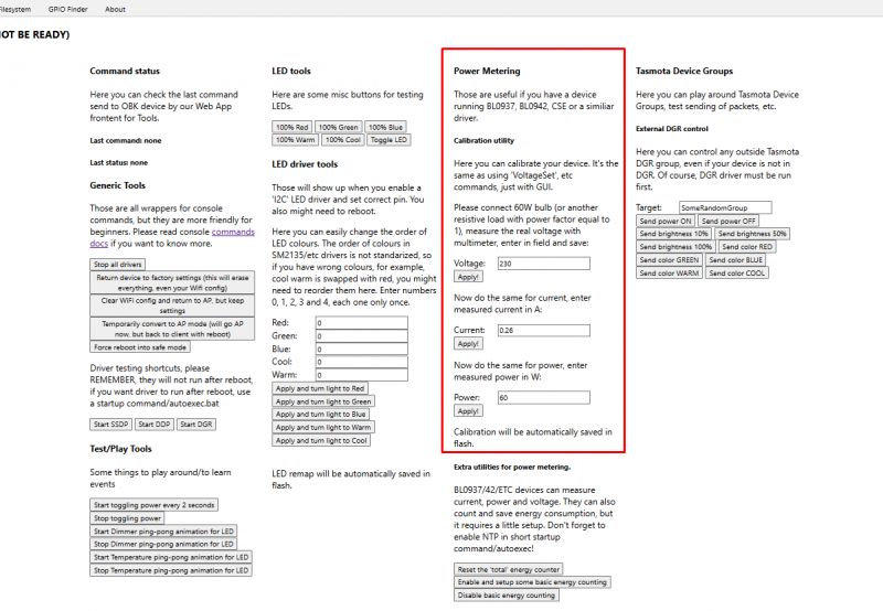
    BL0937 can be easily calibrated in a similiar way we do it in Tasmota, so with VoltageSet/PowerSet/CurrentSet commands. Futhermore, if you have device already paired with your WiFi, you can instead simply use our Web App wrapper in the Tools tab, there is a calibration GUI as well:
    Device calibration interface in a web application, showing the power metering section.
    Helpful post? Buy me a coffee.
  • #35 21390055
    nemetila
    Level 5  
    >>21390039
    Thank you, I found the Calibration utility, I will try it later.
  • Helpful post
    #36 21393106
    nemetila
    Level 5  
    >>21390055
    BL0937 calibration seems working (done with 250W bulb).

    Comparing with Gosund EP2(BL0942) Load: LCD TV+Denon Amplifier:
    - Voltage and Current are almost the same (1-2% difference)
    - Power factor BL0942 : 1.0 vs BL0937 : 0.9

    Measurement device screen displaying electrical energy data.

    Some images from the SP1:
    Electronic module CUCO Z0 R V1.2 on a blue background.
    Close-up of a circuit board with visible traces and markings on a blue background.

    Image of the interior of an SP1 electronic device showing the circuit board and components.
  • #37 21394225
    divadiow
    Level 34  
    >>21393106

    Good stuff

    Please share your OBK template so device can be added to list
  • ADVERTISEMENT
  • #38 21394332
    nemetila
    Level 5  
    >>21394225

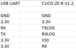
    Flashing pinout:
    Table comparing pins of USB UART and CUCO-Z0-R-V1.2

    Template:
    rtl87x0C66...-44-47.zip Download (493 bytes)

    {
      "vendor": "Tuya",
      "bDetailed": "0",
      "name": "Full Device Name Here",
      "model": "enter short model name here",
      "chip": "RTL87X0C",
      "board": "TODO",
      "flags": "1024",
      "keywords": [
        "TODO",
        "TODO",
        "TODO"
      ],
      "pins": {
        "3": "Rel;1",
        "4": "BL0937SEL;0",
        "11": "WifiLED_n;0",
        "13": "Btn;1",
        "14": "LED_n;1",
        "17": "BL0937CF;0",
        "18": "BL0937CF1;0"
      },
      "command": "",
      "image": "https://obrazki.elektroda.pl/YOUR_IMAGE.jpg",
      "wiki": "https://www.elektroda.com/rtvforum/topic_YOUR_TOPIC.html"
    }
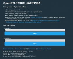


    I set relay: "remember last power state"
    OpenRTL87X0C user interface with pin settings and new start values


    autoexec.bat:
    
    startDriver BL0937
    startDriver NTP
    ntp_timeZoneOfs 01:00
    PowerSave 0
    VCPPublishIntervals 60 60
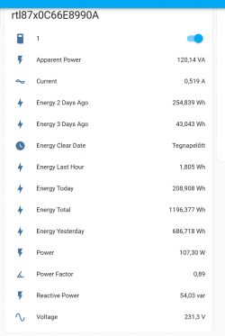


    MQTT and Home Assistant Discovery is OK:
    Screenshot of energy monitoring results in Home Assistant.
  • #41 21395393
    divadiow
    Level 34  
    misread. EP2 was comparison. fixed. thanks
  • #42 21398455
    rudolfbyker
    Level 4  
    p.kaczmarek2 wrote:
    AmebaZ2 PG Tool 1.2.47

    Do you have a download link for this? I can't find it anywhere.

    Sorry, I did not read properly! It's here: https://www.elektroda.com/rtvforum/download.php?id=1238048

    Added after 1 [hours] 38 [minutes]:

    My USB-UART won't work on Windows, so I tried on Linux, and I got it working using `ltchiptool`:

    
    $ pip install ltchiptool


    $ python -m ltchiptool flash write --device /dev/ttyUSB0 "/home/dolf/OpenRTL87X0C_1.18.21.bin" 


    I: Detected file type: Realtek AmebaZ2 Flash Image
    I: Connecting to 'Realtek AmebaZ2' on /dev/ttyUSB0 @ 115200
    I: |-- Success! Chip info: RTL8720CF
    I: Writing '/home/dolf/OpenRTL87X0C_1.18.21.bin'
    I: |-- Start offset: 0x0 (auto-detected)
    I: |-- Write length: 719.1 KiB (auto-detected)
    I: |-- Skipped data: 0 B (auto-detected)
      [################################################################]  100%          I: Transmission successful (ACK received).
    I: Transmission successful (ACK received).
    
    I: |-- Finished in 79.313 s


    The enable pin was not needed. For the rest, the wiring was the same as in the guide at the top of this thread.

    Added after 47 [minutes]:

    (I wanted to post this at https://www.elektroda.com/rtvforum/topic3979433.html but that topic is locked now. I'm not sure if this is the right place to post it.)

    For the device described at https://www.elektroda.com/rtvforum/topic3979433.html , which is sold as "Tuya Basic Smart WiFi Switch 10A" in South Africa (see https://www.communica.co.za/products/smart-switch-basic-wifi-tuya-10a?variant=39250494881865 ), the used pins are:

    
    pin  symbol type  function                          Tuya Basic Smart Switch usage
    4    A18    I/O   GPIOA_18, hardware PWM, IC Pin39  LED_n 1
    6    A17    I/O   GPIOA_17, hardware PWM, IC Pin38  Btn 1
    9    A12    I/O   GPIOA_12, hardware PWM, IC Pin26  Rel 1


    The plastic case has a WiFi symbol printed near the LED, so it's probably used as WifiLED_n in the original firmware, but I would rather use it as LED_n to indicate the relay state.

    Here is the template. I don't know what to do with "flags", "keywords", and "command". There seems to be no model number.

    
    {
      "vendor": "Tuya",
      "bDetailed": "0",
      "name": "Tuya Smart Switch Basic WiFi 10A",
      "model": "",
      "chip": "RTL87X0C",
      "board": "JKY101-F-SR-V3.1",
      "flags": "1024",
      "keywords": [
        "TODO",
        "TODO",
        "TODO"
      ],
      "pins": {
        "12": "Rel;1",
        "17": "Btn;1",
        "18": "LED_n;1"
      },
      "command": "",
      "image": "https://obrazki.elektroda.pl/1732280500_1718455167.jpg",
      "wiki": "https://www.elektroda.com/rtvforum/topic3979433.html"
    }
    
  • ADVERTISEMENT
  • #43 21398702
    divadiow
    Level 34  
    nice going. I dunno if certain posts can be moved to other threads - @p.kaczmarek2 - it'd be nice to have it all in one place. I might have device-specific bits to add too :)

    Added after 13 [minutes]:

    or a new thread for @rudolfbyker's generic Tuya/SmartLife variant I guess
  • #44 21420024
    itsmaxdd
    Level 2  
    Hello,
    i'm about to buy a Beca BHT-006GCLW which is supposed to have a WBR3 chip.
    I like the device aesthetically but i'm a bit drawn back by the fact i have to desolder the MCU to use it away from tuya or similar things.

    Do you think that with a dremel one could drill the back side of the board to expose A0 and A15 through the PCB?
    Here it is suggested that the only pin on the back needed to flash is the A0, is that true or do we also need A15? I guess that since it is the LOG_TX it is quite mandatory?
    https://github.com/libretiny-eu/libretiny/issues/235#issuecomment-1875967472
  • ADVERTISEMENT
  • #45 21420124
    divadiow
    Level 34  
    Yes, A15, A16 and A0 are all needed to programme RTL8720CF as seen in image in first post
    Close-up of RTL8720CF electronic module with connected wires.
  • #46 21420169
    itsmaxdd
    Level 2  
    I see, i'm quite new to openbeken.
    How is the main functionality mainteined? After flashing, by dumping the tuya config and converting it?
  • #47 21420173
    p.kaczmarek2
    Moderator Smart Home
    It depends on the device, but usually you either choose the GPIO roles, either manually or via imported template (from Tuya device dump or from our forum/devices list), or you write autoexec script to configure TuyaMCU data points. This way you can more or less mimic the original device functionality or even often add more features.

    Beca BHT-006GCLW looks like TuyaMCU device, so good start is this guide: https://www.elektroda.com/rtvforum/topic4038151.html
    Helpful post? Buy me a coffee.
  • #48 21424128
    seattmm
    Level 9  
    divadiow wrote:
    >>21381809

    how it programming?
  • #49 21515574
    heltonincerti78
    Level 1  
    Hello everyone,

    I’m working on certifying the WBR3 and WBRU modules for use in Brazil.
    For the WBR3, I was able to purchase the conducted module with the certification firmware already installed.
    However, for the WBRU, the supplier is not providing it with the certification firmware.

    Is it possible to dump the firmware from the WBR3 and flash it onto the WBRU?

    Any help would be greatly appreciated.
    Thank you in advance!
  • #50 21515587
    p.kaczmarek2
    Moderator Smart Home
    Welcome to forum, according to the docs:
    
    WBR3 is a low-power embedded Wi-Fi+Bluetooth module that Tuya has developed. It consists of a highly integrated RF chip (W701-VA2-CG), with an embedded Wi-Fi network protocol stack and varied library functions.


    WBRU is a low-power-consumption embedded Wi-Fi+Bluetooth module that Tuya has developed. Embedded with the Wi-Fi network protocol stack and rich library functions, it consists of a highly integrated RF chip (W701-VA2-CG).
    

    both modules are the same chip, so they should run, but maybe @divadiow and/or @insmod can confirm this to be sure.

    PS: As in the first post, W701-VA2-CG = RTL8720CF

    PS2: Do you want to transplant full firmware backup, or only the program? Currently I am not sure about RF stuff, the calibration could be per-device...
    Helpful post? Buy me a coffee.
  • #51 21516172
    divadiow
    Level 34  
    I've not had cause to carve up an Realtek dump to preserve RF areas before, but is the main question what tool can be used to take a backup from the WBR3?

    We've explained the process of backing-up AmebaZ and AmebaD (if you dig through some posts - Py flash tools here https://github.com/openshwprojects/FlashTools/tree/main/Realtek ), but not Z2. We need an rtltool for Z2, or there's LT for now...

    I do keep thinking we need some RTL firmware backup guides
  • #52 21516179
    insmod
    Level 23  
    I don't believe system/calibration data can be read. And most likely can't be written.
    System data is stored at 0x1000-0x2000 and calibration data is at 0x2000-0x3000.
    If you check any dump, you won't find anything (i surely didn't). All data is 0xFF.
    Or perhaps it's just not used and everything is written in efuse. I know that MAC address is.
  • #53 21531209
    kalikum
    Level 5  
    Hi everyone,

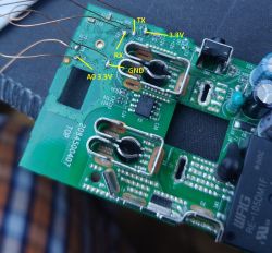
    Following the information I found https://www.elektroda.com/rtvforum/topic4097185.html, I was able to flash version 1.18.91 of the RTL8710CF chipset onto my Tapo P110. I'm sharing the pins where the connections go. I made the mistake of not documenting the power control pins before assembling and closing it, so if anyone has this information, we could complete the setup.

    I only have this image
    PCB with marked connection points: TX, RX, GND, AO 3.3V, 3.3V – labeled in yellow.

    Webportal
    Screenshot of the OpenRTL87X0C device control panel showing device status, buttons, and technical details.

    Template not complete yet:
    {
      "vendor": "Tuya",
      "bDetailed": "0",
      "name": "Full Device Name Here",
      "model": "enter short model name here",
      "chip": "RTL87X0C",
      "board": "TODO",
      "flags": "1024",
      "keywords": [
        "TODO",
        "TODO",
        "TODO"
      ],
      "pins": {
        "12": "Rel;1",
        "17": "Btn;1",
        "18": "LED_n;1",
        "19": "LED;1"
      },
      "command": "",
      "image": "https://obrazki.elektroda.pl/YOUR_IMAGE.jpg",
      "wiki": "https://www.elektroda.com/rtvforum/topic_YOUR_TOPIC.html"
    }


    I am very sorry to don't have more details of the process I followed, I thought it too late. :(

    Thank you very much for all the information you posted, without you literally this could not be done.

    Sorry if there is any grammatical error, I use translator
  • #54 21531212
    p.kaczmarek2
    Moderator Smart Home
    Maybe we could try to read the device Tuya config via the Web App? I'm not sure if the offset is updated there. Still, we also have that option to read full 2MB. That would certainly include your SSID and so on, but could also include the Tuya config.
    Helpful post? Buy me a coffee.
  • #55 21531222
    kalikum
    Level 5  
    Can it be done without opening the switch or welding cables? I have thought about buying another and documenting it well, although I don't know when I could do it.
    If I do, I will share it, I am sure.
  • #56 21531234
    p.kaczmarek2
    Moderator Smart Home
    It is done in software, but I am not sure if it's implemented on this Realtek yet. I am talking about flash read option in the web app:
    Screenshot of an IoT device management panel at 192.168.0.163, Flash tab, showing options to read, download, and write configuration files.
    Helpful post? Buy me a coffee.
  • #58 21531614
    kalikum
    Level 5  
    >>21531234
    Thanks, I'm going to check

    >>21531238
    No, it's a tapo p110 EU but with the chip RTL8710CF

    Close-up view of the back of a TP-Link Tapo P110 smart plug with visible markings and prongs.
  • #59 21537845
    kalikum
    Level 5  
    >>21531209

    Little update.

    Template:

    Code: JSON
    Log in, to see the code


    Chip on Tapo P110 RTL8710CF
    Close-up of a Realtek RTL8710CF microchip on a green PCB with visible electronic components.

    Consumption operation, Not calibrated yet .

    Device control panel screen with voltage, current, and power information.

    Finally I have disassembled and followed the ways to the chip.

    Block diagram and pinout of the BL0937 chip in SOP8 package.
    Table describing the pin functions of the BL0937 IC, listing pin numbers, symbols, and detailed descriptions.

    Thanks again for information.

Topic summary

The discussion focuses on flashing and configuring various Tuya-based modules, specifically those utilizing the RTL8720CF chip, such as WBR1, WBR2, WBR3, and W701-VA2-CG. A step-by-step guide for flashing these devices using the AmebaZ2 PG Tool is provided, allowing users to operate them without cloud dependency and integrate them with Home Assistant and Tasmota. Participants share insights on pinouts, boot logs, and the reliability of different flashing methods, including UART connections and potential modifications to access necessary pads. The conversation also touches on the calibration of devices and the collection of firmware dumps for further development.
Summary generated by the language model.
ADVERTISEMENT