logo elektroda
logo elektroda
X
logo elektroda
ADVERTISEMENT
Treść została przetłumaczona polish » english Zobacz oryginalną wersję tematu
  • #181 9079844
    Moyshaa
    Level 14  
    3-pin motor.
    2A power supply.
    I have 2 TDAs and both are the same.
    TDA heats up a bit, it's hard to say whether it is too much (40-45 degrees "on the finger"), because I do not know what temperature it should be.
    Capacitors - OMG! Instead of CD DC ST TI soldered in reverse.

    Tomorrow, when I buy a new and decent suction unit, I will let you know what came out of it.

    Thanks for the help. And sorry for the carelessness that caused me to need her.

    ----

    However, I sold them today. Of course it works. Thanks again. :)
  • ADVERTISEMENT
  • #182 9304846
    mateo238
    Level 10  
    I made myself a simple spectral display. However, when I try to display something on it, the image doubles for me (I want to display the letter F and I get FF). What could this be the result of? We attach the code (very poor so far). Help me.

    [syntax=c]#include
    #include
    #include

    volatile char licznik = 0;
    char tablica[6];

    ISR( INT0_vect )
    {
    licznik=0;
    }

    ISR( TIMER1_OVF_vect )
    {
    TCNT1=65490;
    if(licznik
  • ADVERTISEMENT
  • #183 9305112
    Moyshaa
    Level 14  
    Everything is fine, but why don't you write comments?

    [code:1:5a7ee9b75b]MCUCR |= 1
  • #184 9305205
    mateo238
    Level 10  
    In fact, there was a problem here. Thanks a lot!

    PS. I did not write comments because I found that the project is so poor so far that there is nothing to comment on.
  • #185 9311877
    sliderps
    Level 15  
    Hello,
    a really cool project - I used to create a DIY construction myself ;)

    http://www.allinbox.com/Black_giant/Black_giant.htm

    Now we started classes on Microprocessors and microcontrollers and we agreed to do the spectral clock. As it is a really interesting project - we do not know how to go about it. So far, the leader gave us a list of items to buy + the old disk that we should use. The question is, what elements did the author of the project use exactly and how much did they cost? apart from programming it in C, assembling and soldering elements is also troublesome?
  • ADVERTISEMENT
  • #186 9312079
    Anonymous
    Level 1  
  • #187 9528983
    krzysiek841
    Level 11  
    Hello dear colleagues!

    I would like to assemble such a clock in RGB version, made in smd technology, on the atmega32L-8AU microcontroller. I already have such a microcontroller and 20 smd rgb diodes with a common anode. I would ask my colleagues for any ideas about the scheme and software that I could use. I am going to make the clock very professionally with attention to detail. I would like it to have smooth transitions between colors, the ability to set a selected color in the menu by increasing or decreasing the display of each color. Of course, it would be controlled by an rc5 remote control and would have a contactless transformer as a power supply. I would also like to be able to upload and display subtitles, graphics, etc. I would also like to take into account that the LEDs closest to the center seem to shine brighter than those at the end of the tonearm and reduce this effect. I thought to make a version with 16 LEDs at the beginning, then maybe 24 and 32. I have various types of fans, also the use of a hard drive motor would be an option (I have one such copy that turns immediately after connection and does not need a head to work :P ). I have already dealt a lot with the soldering iron and SMD assembly is not a problem for me. The project would be quite extensive, so I would like to ask for help. I can buy parts, there is also another microcontroller (additional memory, etc.) I can design and make the board, only please help me make a diagram and software :)
    greetings
  • #188 9622756
    sarsik87
    Level 11  
    How to check the frequency of the motor's rotation? What factor could I use instead of hdd to keep it relatively small but with more force (more speed) ??
  • #189 10424208
    robotonic3d
    Level 1  
    please i need a material list and pcb layout maybe a design or schematic or photo that make the pcb io porfa thankful this is the best design i have ever seen and i hope thanks your reply in advance.

    please I need the list of materials and PCB circuit can project or the circuit diagram or photo would make the pcb io porfa grateful it is the best project I've ever seen and I hope your answer thanks in advance.
  • #190 10426677
    Moyshaa
    Level 14  
    When you don't use punctuation marks, the translator cannot translate correctly and what you write sounds funny and hard to understand.
    What you need is in the post # 72 .
    ---
    If you do not use punctuation marks, the translator can not translate properly, and what you write sounds ridiculous and it is hard to understand.
    What you need is in post # 72 .
  • #191 10655127
    RazoR253
    Level 10  
    Could someone create .pdf files with top and bottom rotor layers?
    I can't cope with the protel service for anything.
  • #192 10812387
    heop
    Level 2  
    Has someone designing the board in dxf format. or in some other only if the paths were drawn with vectors?
  • #193 11044717
    bobek19926
    Level 9  
    Could someone upload the engine and propeller driver project in a .brd file?
    To play the program Eagle.
  • #194 11174820
    Milos8905
    Level 2  
    Can somebody send me PCB scheme of this project? Thank you
  • #196 11218886
    samito22
    Level 1  
    hi, somebody can send me the part list et PCB scheme of this project?
    thank you.
  • #197 11254263
    Milos8905
    Level 2  
    Which programmer you use for this microcontroller ATMEGA32? I can't find any programmer in Serbia for it. Can you send schematic for programmer? Tnx
  • #199 11268694
    Milos8905
    Level 2  
    Can I use programmer http://programatory-usb.pl/ for SMD Atmega32? Can you explain me how to connect my microchip with programmer, and everything whit it, because I'm new in this... Thank you...
  • #200 11271685
    psooya
    Level 38  
    Hello
    I haven't read the whole thread (7 pages) but I like the project and I have an interesting idea. To power the uC, you could use a stepper motor mounted on the axis of the motor driving the display. You would have to do this so that, for example, the stator should be attached to the ground and the axis of the driving motor passed through the axis of the stepper and drove both his and the plate. You could probably think of it better, but I figured it out right now and suggest it for the future.
  • #201 11283575
    H2QA
    Level 1  
    How to set time?
    This circuit you can remote?

    Added after 3 [minutes]:

    How do I set the time?
    This circuit can be a remote control?
  • #202 11465837
    DJCheester
    Level 26  
    Hello, I am going to make such a clock, but I do not have a protel and I have a request if someone could provide the path layout in pdf so that I could print (laser) on chalk paper and etch the PCB. Thanks in advance for your time ...
  • #203 11652360
    psychoticpolice
    Level 1  
    what program did you use to open this
    [/ b]
  • #204 11696510
    mwp05
    Level 12  
    Colleagues, I give up, I've been struggling with files from the front page for several days:
    BLCD Driver.ddb and PropClock_v2.Ddb and apart from disk clutter, I didn't achieve much.
    Before yesterday, I was able to see PCB printing with elements, but it was not possible to separate it to have two files separately. Print for thermal transfer and description of assembly of elements.

    At this point, I am at the starting point, i.e. I have cleaned the disk from all versions of the protel, viewer and ... and I am at the starting point, i.e. with nothing.

    Would someone be so nice and put these files in pdf into the thread,
    I mean BLCD Driver.ddb and PropClock_v2.Ddb (print view and assembly view).
    If someone was working on this diagram, it can be in eagle or KiCad because I doubt there would be any conventions.
  • #205 11814726
    Latino33
    Level 1  
    I warmly welcome!
    First, I am very impressed with this watch. The project is amazing and (as you can see) very popular. I have been hanging around this forum for a long time and made the decision that I would finally start doing something. I am a complete amateur and all I could do is soldering. That's why I think that if I throw myself into deep water and spend some time on this watch, I will learn a lot.

    So this: regarding the post above. On the third page of this topic, Slaba's colleague added photos from these files in a .pdf file.

    Now my question. Could someone write or where can I buy such a plate for a propeller. As I said, I can't do much, that's why I'm asking about the basics. You could probably make the plate from the photo based on this lamp yourself. But I don't know about the propeller anymore :D

    Please reply and once again Hello :D
  • #206 11815841
    mwp05
    Level 12  
    Latino33 wrote:


    So this: regarding the post above. On the third page of this topic, Slaba's colleague added photos from these files in a .pdf file.


    Well ... I only see pdf with diagrams but it doesn't matter anymore, I'll look for something else.
  • #207 12007461
    hetm4n
    Level 20  
    Hello, I put this clock on the air hit and it works, but I have a problem, the DS does not count the time, it shows 00.00.80, I only uploaded the author's flash, I can not upload eeprom because avrstudio4 pops up that the eeprom file is empty.

    and here is a link to the video how it works.


  • ADVERTISEMENT
  • #208 12010375
    mb1988
    Level 12  
    Hi,

    First, congratulations on your modification. With your power solution, the watch runs much quieter than mine. Secondly, it's nice that someone after five years is still digging up this (underdeveloped) project and trying to do something about it ;-) .

    The mysterious 00:00:80 is a familiar mystery in the case of the DS1307. This strange eight is the highest bit in the seconds register. To quote the datasheet
    Quote:
    Bit 7 of Register 0 is the clock halt (CH) bit. When this bit is set to 1, the oscillator is disabled. When cleared to 0, the oscillator is enabled. On first application of power to the device the time and date registers are typically reset to 01/01/00 01 00:00:00 (MM / DD / YY DOW HH: MM: SS). The CH bit in the seconds register will be set to a 1.

    This means that it was not so much the DS did not take off as did not start :-) . This is because this project uses a very twisted time setting system, which requires you to upload two different hexes one after another :P . One of them has a compiled time which it sets and thus deletes that control bit, and the other one does not do it anymore. To check if the watch will start, I put a hex in the attachment, which should set the time to 15:00 with today's date. If you upload it at 3 p.m. with the backup battery inserted, and then, without turning off the power, you upload the hexa available in the archive on the first page of this topic, the time will be read correctly forever.

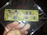
    However, there is also a modification that I do not know if I mentioned on the previous pages of the topic. Namely, it is a resistor pulling the break line from DS. Without it (or without any changes in the software), the time, although it will be different from 00:00:80, will not change. I marked the resistor in question in the photo.

    Spectral Clock - Propeller Clock
  • #209 12994949
    robocp1992
    Level 10  
    Hello, I am starting to make this clock, but I have a problem with getting the MBI5170 LED servos. Could someone help and tell me what I can replace, or indicate an online store where I can get them? Alternatively, if someone knows where you can get such drivers in Krakow, I would also be grateful.
  • #210 12995498
    mlassota
    Level 18  
    Sorry for pasting the link, but they are available HERE - this one fits: MBI-5170GD IC, 8-channel LED driver, SOP16L-150-1.27
    One more tip - I suggest choosing LEDs with the highest possible brightness. The diode is on for a very short time and the standard ones are not visible from a distance

Topic summary

The discussion revolves around the design and implementation of a spectral clock using a propeller mechanism. The project utilizes an ATMEGA32 microcontroller to control 32 blue SMD LEDs via MBI5170 LED drivers, with timekeeping managed by a DS1307 RTC. Participants share insights on motor control, programming in C, and the challenges of achieving precise synchronization for the display. Various users inquire about the specifics of the circuit, including the use of different LED drivers, the programming process, and the durability of components. Suggestions for improvements, such as using a coreless transformer for power and implementing IR communication for time setting, are also discussed. The community expresses interest in obtaining schematics, PCB layouts, and a bill of materials for the project.
Summary generated by the language model.
ADVERTISEMENT