
I bought a couple of these and managed to get it working with OpenBeken:

Some info:
- Webshop link
- Datasheet
- Product code: 3208075
- CBLC5 module with BK7231N
- LED driver (U2) is a SM2185N
- The 3v3 for the CBLC5 module is provided by a BP2571 buck converter.
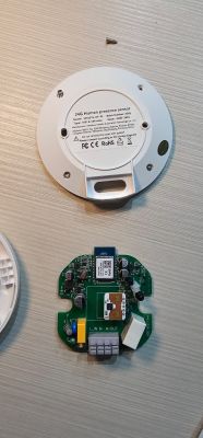
This post has a really good description how to disassemble this device: https://www.elektroda.com/news/news3948374.html
To remove the metal threads, I simply screwed the bulb into a socket and gently pushed the bulb off the socket.
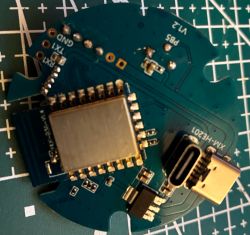
To program it, it is at least necessary to solder wires on the UART TX and RX pads of the CBLC5 module. To get to the pins it is sometimes necessary to remove the white glue a little bit. The picture below shows the pads T1 and R1 (sorry for the mess, this was already after I desoldered the wires again). There is also a reset pad, but it is not necessary connect if you use the right tool to program.

If you have clamps it is not necessary to solder wires to power the device. I found the following two locations are easy to clamp and are connected straight to the GND and VCC of the CBLC5 module.

Here is a pinout of the CBLC5 module I found on the internet:

Initially I failed to get the programming to work. It turns out that the device really, really needs the correct voltage. Often the 3.3V supply of USB - UART adapters do not deliver enough current. But even when I used a separate LDO to provide the power programming failed because I had too many wires and connections between the LDO and the CBLC5 module, causing a voltage drop which was too large.
To program the firmware, I used this tool: https://github.com/tuya-cloudcutter/bk7231tools It doesn't need the reset line to be connected (earlier I used hid_download_py, but it does need the reset line).
Edit: Note that version 1.18.245 or newer is required.
When OpenBeken is running, the following steps were necessary to get the light working:
1. Configure Module:
- Set P24 (PWM4) to SM2235DAT,
- Set P26 (PWM5) to SM2235CLK.
2. Configure General/Flags: Select Flag 4 - [LED] Force show RGBCW controller (for example, for SM2135 LEDs, or for DGR sender),
3. Restart the device.
4. Execute this command to swap the Cool and Warm, Red and Blue, channels.
5. Execute a command to configure the correct clock I2C speed (the default is too fast)
6. Execute this command to set the correct currents (8 mA for RGB leds, 15 mA for white cold and warm). The default settings are too high, I guess this will really shorten the life of your LED bulb if you don't set this.
WARNING: The SM2235_Map command is persistent, the mapping is stored in the configuration in flash memory. The SM2235_Current command is NOT stored in the configuration, and therefore it is necessary to add it as a startup command.
ANOTHER WARNING: Do not use Flag 12 ([LED] Remember LED driver state (RGBCW, enable, brightness, temperature) after reboot). The state of the LED driver is restored _BEFORE_ startup commands are executed, so the LEDs will run with too much current after a reboot. This has been fixed in version 1.18.245, the current settings are applied immediately if the command is executed now.
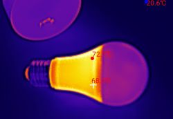
This worked fine for the first bulb that I programmed. However, the other two showed weird behavior. Initially the LED worked correctly, but after some time setting a color resulted in white light or vice verse. Even turining off the light failed more often than not (it just changed to a random color or brightness).
Because I initially didn't know about the need to configure the correct current with SM2235_Current (and I didn't make a backup), I bought another one and attached a scope to figure out which current settings the original firmware applies (the first two bytes are 11011000 00010010). I also noticed that the I2C bus runs at about 50 kHz. I didn't measure the I2C clock of OpenBeken, but I noticed that the firmware probably uses a clock of 400 or 500 kHz. The SM2185N datasheet specifies that I should work with 1000 kHz, but lowering the clock rate solved the problem anyway.
I created a pull request to make the I2C clock frequency configurable with a command: https://github.com/openshwprojects/OpenBK7231T_App/pull/1928
Edit: change is merged, it is possible to configure a I2C clock that has no problems with this command:
Here is picture of the LED controller IC

Another posts that helped me: https://www.elektroda.com/rtvforum/topic4014350.html

Some info:
- Webshop link
- Datasheet
- Product code: 3208075
- CBLC5 module with BK7231N
- LED driver (U2) is a SM2185N
- The 3v3 for the CBLC5 module is provided by a BP2571 buck converter.
This post has a really good description how to disassemble this device: https://www.elektroda.com/news/news3948374.html
To remove the metal threads, I simply screwed the bulb into a socket and gently pushed the bulb off the socket.
To program it, it is at least necessary to solder wires on the UART TX and RX pads of the CBLC5 module. To get to the pins it is sometimes necessary to remove the white glue a little bit. The picture below shows the pads T1 and R1 (sorry for the mess, this was already after I desoldered the wires again). There is also a reset pad, but it is not necessary connect if you use the right tool to program.

If you have clamps it is not necessary to solder wires to power the device. I found the following two locations are easy to clamp and are connected straight to the GND and VCC of the CBLC5 module.

Here is a pinout of the CBLC5 module I found on the internet:

Initially I failed to get the programming to work. It turns out that the device really, really needs the correct voltage. Often the 3.3V supply of USB - UART adapters do not deliver enough current. But even when I used a separate LDO to provide the power programming failed because I had too many wires and connections between the LDO and the CBLC5 module, causing a voltage drop which was too large.
To program the firmware, I used this tool: https://github.com/tuya-cloudcutter/bk7231tools It doesn't need the reset line to be connected (earlier I used hid_download_py, but it does need the reset line).
Code: Bash
Edit: Note that version 1.18.245 or newer is required.
When OpenBeken is running, the following steps were necessary to get the light working:
1. Configure Module:
- Set P24 (PWM4) to SM2235DAT,
- Set P26 (PWM5) to SM2235CLK.
2. Configure General/Flags: Select Flag 4 - [LED] Force show RGBCW controller (for example, for SM2135 LEDs, or for DGR sender),
3. Restart the device.
4. Execute this command to swap the Cool and Warm, Red and Blue, channels.
Code: Text
5. Execute a command to configure the correct clock I2C speed (the default is too fast)
Code: Text
6. Execute this command to set the correct currents (8 mA for RGB leds, 15 mA for white cold and warm). The default settings are too high, I guess this will really shorten the life of your LED bulb if you don't set this.
Code: Text
WARNING: The SM2235_Map command is persistent, the mapping is stored in the configuration in flash memory. The SM2235_Current command is NOT stored in the configuration, and therefore it is necessary to add it as a startup command.
Because I initially didn't know about the need to configure the correct current with SM2235_Current (and I didn't make a backup), I bought another one and attached a scope to figure out which current settings the original firmware applies (the first two bytes are 11011000 00010010). I also noticed that the I2C bus runs at about 50 kHz. I didn't measure the I2C clock of OpenBeken, but I noticed that the firmware probably uses a clock of 400 or 500 kHz. The SM2185N datasheet specifies that I should work with 1000 kHz, but lowering the clock rate solved the problem anyway.
I created a pull request to make the I2C clock frequency configurable with a command: https://github.com/openshwprojects/OpenBK7231T_App/pull/1928
Edit: change is merged, it is possible to configure a I2C clock that has no problems with this command:
Code: Text
Code: JSON
Here is picture of the LED controller IC

Another posts that helped me: https://www.elektroda.com/rtvforum/topic4014350.html
Cool? Ranking DIY
