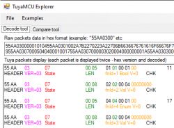
Here is a small program that allows you to analyze the content of TuyaMCU eavesdropped packets. The program shows the type, length and content of the packet, broken down into dpID variables, their types and values. The program allows you to quickly find out what the dpID we overheard contain - whether it is, for example, a dimmer value or, for example, a relay state, or maybe it is a voltage or current value. The program shown here is useful in the process of releasing a given IoT product from the cloud, because this process requires us to determine the available dpIDs for a given product, because these dpIDs are different for different products.
Related Topics TuyaMCU is a UART-based protocol through which the WiFi module communicates with an additional microcontroller on board the device. In the case of devices with TuyaMCU, the WiFi module usually only reports data to the network, and the MCU itself supports relays, buttons, LCD or sensors and measuring systems.
For more details, I invite you to the topic about TuyaMCU itself:
TuyaMCU protocol - communication between the microcontroller and the WiFi module In addition, it is worth seeing examples of devices using TuyaMCU:
-
WF-DS01 SmartLife/Tuya WiFi switch/dimmer for box - diagram -
EDM-01AA-EU 300W dimmer for BK7231 and TuyaMCU - configuration -
HomeMate Wi-Fi + Bluetooth Smart 4 Gang Touch Switch -
Tuya ATORCH AT4P(WP/BW) Smartlife Energy monitor (BK7231N) (C3BS) (CH573F) (BL0924) -
QIACHIP Universal WIFI Ceiling Fan Light Remote Control Kit - BK7231N - CB2S -
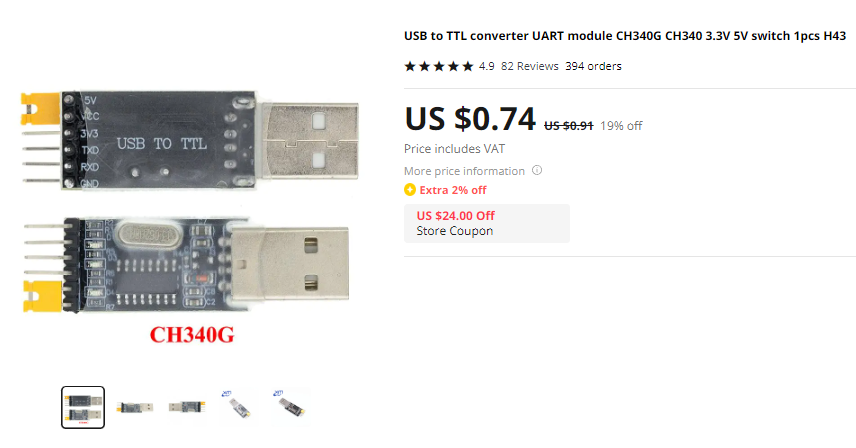
Energy-saving (?) battery door/window sensor for WiFi DS06 TuyaMCU packet capture Capturing TuyaMCU packets is really very simple. One USB to UART converter is enough:
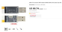
Just power from USB (
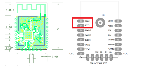
not from the web! everything should be unplugged ) our device, connect 5V from USB before the 3.3V LDO regulator on board, which will also provide a stable 3.3V for the WiFi module, and then solder with ground and signal wires on RX and TX. For example, for WB3S:
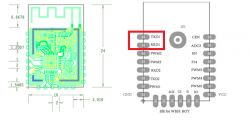
In the case of Tuya modules, the same UART is used to program the module via the bootloader and to communicate with TuyaMCU, which can sometimes be problematic. When changing the firmware, I often have to desolder the WiFi module in this case or break the path (and then reconstruct it).
UART is a bi-directional bus, so first we capture from the TuyaMCU TX line -> WiFi RX module, and then from the WiFi line TX module -> TuyaMCU RX
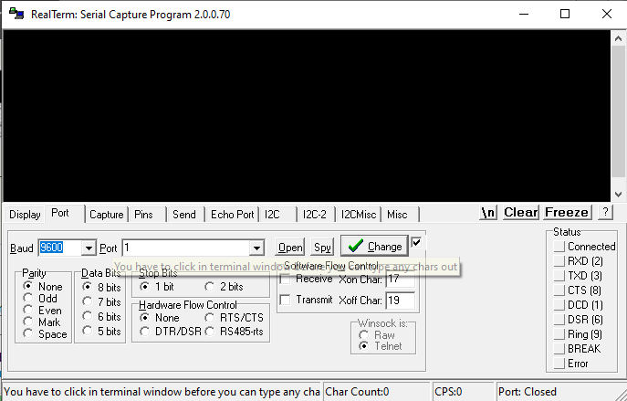
Capturing is easy to do in RealTerm:
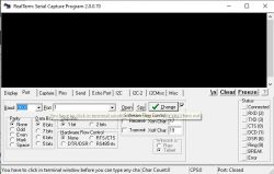
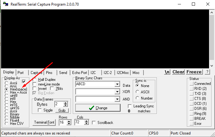
It is best to choose hex with spaces (not binary):
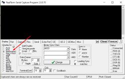
Then you should enable writing to the file, so it's more convenient:
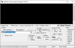
Capture Steps:
1. connect the USB to UART converter to the device, but do not connect the 5V from USB to its power yet (do not turn on the device)
2. start capturing, first e.g. from TuyaMCU TX line -> WiFi RX module
3. perform selected operations on the device
4. finish capturing
5. repeat points 1, 2, 3 and 4, but in point 2, connect to the WiFi line of the TX module -> TuyaMCU RX
I recommend doing separate packet captures for different operations, e.g.:
- separately for starting the device
- separately, e.g. for dimmer status changes (changes in brightness level)
- separately for on/off
- separately for other settings (if available), e.g. in the case of devices with energy measurement, it is worth doing a separate capture for different voltages and saving these voltages, then you can compare packets on this basis and look for where the voltage value is saved, etc. Same with power - do a capture when measuring the load 30W and then 100W, etc.
Using two USB to UART converters it could be improved, but it would also be nice to have some software that saves communication from two COM ports at once.
TuyaMCU analyzer The program can be downloaded from Github, already in compiled form:
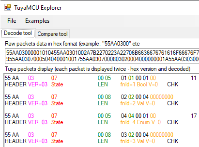
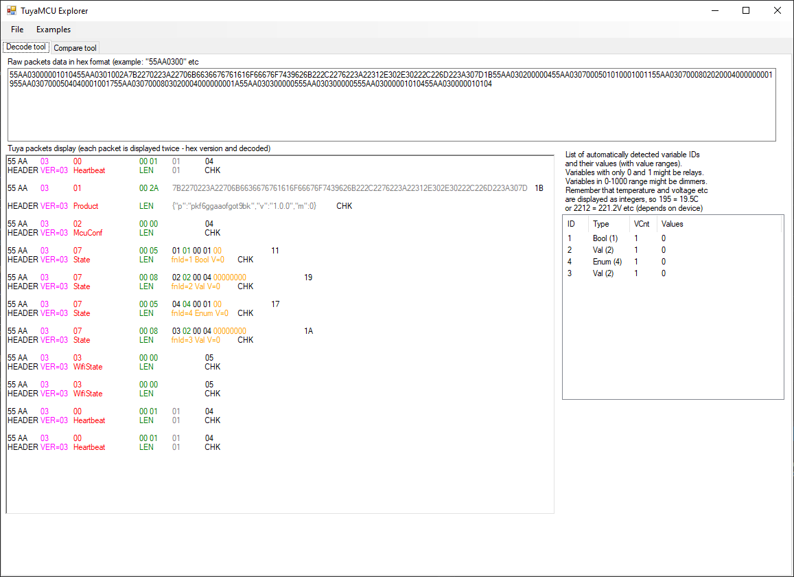
https://github.com/openshwprojects/TuyaMCUAnalyzer After running the program, we already have a sample package entered:
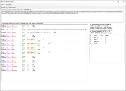
To the field
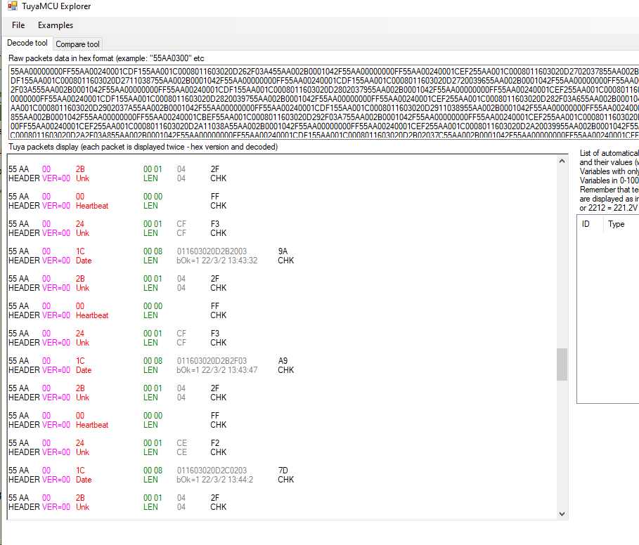
Raw packet data we can paste the hex record of packets captured by, for example, Realterm. The system allows spaces and transitions to the next line between hex codes, this is used to increase readability.
Field
Tuya packets display shows each packet twice - first it breaks its bytes into divisions according to their role and colors them, and below it gives their roles and interpretations.
Plus a section
List of automatically detected variable IDs contains a summary of detected dpIDs along with their captured values. This can help, for example, in determining which value is, for example, the brightness level of the dimmer, i.e. it usually has values from 0 to 1000. On the other hand, the relay states can only be 0 or 1.
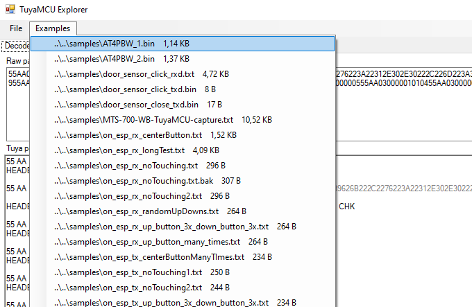
In addition, the program offers a set of sample packages loaded from the folder
samples , they are available in this menu:
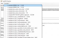
The .bin extension means a binary file, with packets as bytes, while .txt means a text file, where packets are already saved as hex codes (already in ASCII, human readable).
Also, there is a bookmark
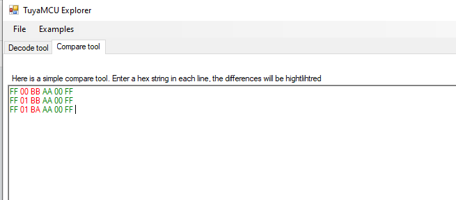
Compare tool , which is a tiny tool useful for determining what has changed in the packages when, for example, we changed the color of the lamp (e.g. the Miboxer led strip controller uses TuyaMCU):
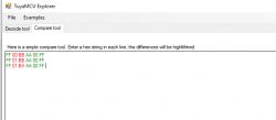
The program treats each line as a separate packet. If the given byte in each line is the same, it is highlighted in green, otherwise it is in red.
Some examples Examples are included in the samples directory. Here is a short presentation of some of them.
Dimmer from TuyaMCU: 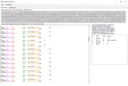
The above packets were intercepted on the line WiFi module TX -> TuyaMCU RX. Here in the summary you can see that dpID 1 of type bool has values 1 and 0, that is, the state of the switch, on or off. In turn, dpID 2, of the value type, has values from 0 to 570, which is probably a dimmer. 570 is the maximum value recorded during the tests, while you can guess from this that the full brightness of the light is 1000, as usual.
Thermometer/Hygrometer/Clock/Calendar TH06: 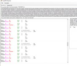
This set of packets shows how the WiFi module sends time to the main MCU from TH06. On the other hand, broadcast by the MCU we have:
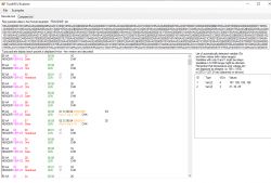
The MCU supports the thermometer and hygrometer, so it sends these measurements to the WiFi module. The temperature is multiplied by 10, because the values here must be integers, and the manufacturer wanted to support up to one digit after the decimal point.
What does the program not help with? Basically, there is one situation where this program cannot help. Some of the more advanced Tuya electricity meters (higher-end, already DIN rail, in the price range of PLN 100 or more) use TuyaMCU to report measurements, but often report a group of measurements in one dpID. Then such a dpID is of the Raw type (no longer Value) and contains several bytes in which (depending on the device) data such as the current value of voltage, current, power, sometimes frequency are stored. Such a raw package has a device-dependent format and it is difficult to decode it more universally.
Cheaper products with energy measurement, in turn, do not use TuyaMCU, rather BL0937 or BL0942 are directly connected to the WiFI module there.
Application for OpenBeken This analyzer allows you to set up quickly
OpenBeken to work on your device with TuyaMCU. Here it is
autoexec.bat from the OBK. These scripts map values from TuyaMCU (those dpID) to OBK variables and allow further processing of these values, determine how values are displayed on the web panel, etc.:
- EDM-01AA-EU dimmer
setChannelType 1 toggle
setChannelType 2 dimmer
tuyaMcu_setBaudRate 115200
tuyaMcu_setDimmerRange 1 1000
// linkTuyaMCUOutputToChannel dpId verType tgChannel
linkTuyaMCUOutputToChannel 1 bool 1
linkTuyaMCUOutputToChannel 2 val 2
dpID 1 is a bool type, it is the on/off state of the light. dpID 2 is value, value from 1 to 1000 is dimmer level.
- QIACHIP Universal WIFI Ceiling Fan Light (fan and light)
startDriver TuyaMCU
// let's say that channel 1 is dpid1 - fan on/off
setChannelType 1 toggle
// map dpid1 to channel1, var type 1 (boolean)
linkTuyaMCUOutputToChannel 1 1 1
// let's say that channel 2 is dpid9 - light on/off
setChannelType 2 toggle
// map dpid9 to channel2, var type 1 (boolean)
linkTuyaMCUOutputToChannel 9 1 2
//channel 3 is dpid3 - fan speed
setChannelType 3 LowMidHigh
// map dpid3 to channel3, var type 4 (enum)
linkTuyaMCUOutputToChannel 3 4 3
//dpId 17 = beep on/off
setChannelType 4 toggle
linkTuyaMCUOutputToChannel 17 1 4
//
//
//dpId 6, dataType 4-DP_TYPE_ENUM = set timer
setChannelType 5 TextField
linkTuyaMCUOutputToChannel 6 4 5
//
//
//dpId 7, dataType 2-DP_TYPE_VALUE = timer remaining
setChannelType 6 ReadOnly
linkTuyaMCUOutputToChannel 7 2 6
Here dpID 1 is bool, it turns the fan on and off. dpID 9 is the state of the light - on or off, also boolean. dpID 3 is the fan speed - three possible values, 0, 1, 2, low, mid or high. Next, dpID 6 is the setting of the timer (countdown) after which the device will turn off, this timer already supports the MCU. Then dpID 7 is the read only variable, the current value of the countdown timer. There is also dpID 17, which controls the sound signal when configured, e.g. from the RF remote control (on or off)
- configuration TH06 hygrometer/LCD/calendar
startDriver TuyaMCU
startDriver NTP
// dpID 1 is tempererature div 10
setChannelType 1 temperature_div10
linkTuyaMCUOutputToChannel 1 val 1
// dpID 2 is % humidity
setChannelType 2 Humidity
linkTuyaMCUOutputToChannel 2 val 2
Here, dpID 2 is the humidity level, and dpID 1 is the temperature, where the temperature is multiplied by 10 because val is an integer type and the manufacturer wanted to transfer values of the type 20.5 degrees
- BlitzWolf BW-AF1 fryer:
startDriver TuyaMCU

// cook on/off
setChannelType 1 Toggle
setChannelLabel 1 "Cook"
linkTuyaMCUOutputToChannel 111 bool 1
// power on/off
setChannelLabel 2 "Power"
setChannelType 2 Toggle
linkTuyaMCUOutputToChannel 101 bool 2

// set temperature
setChannelLabel 3 "New Temperature"
setChannelType 3 TextField
linkTuyaMCUOutputToChannel 103 val 3

// currenttemperature
setChannelLabel 4 "Current Temperature"
setChannelType 4 ReadOnly
linkTuyaMCUOutputToChannel 104 val 4

// set time
setChannelLabel 5 "New Time"
setChannelType 5 TextField
linkTuyaMCUOutputToChannel 105 val 5

// read time
setChannelLabel 6 "Current Time"
setChannelType 6 ReadOnly
linkTuyaMCUOutputToChannel 106 val 6


alias cook185c15min backlog setChannel 2 1; setChannel 3 185; setChannel 5 15; setChannel 1 1
alias cook170c30min backlog setChannel 2 1; setChannel 3 170; setChannel 5 30; setChannel 1 1


startDriver httpButtons
setButtonEnabled 0 1
setButtonLabel 0 "Set 185C 15minutes"
setButtonCommand 0 "cook185c15min "
setButtonColor 0 "orange"


setButtonEnabled 1 1
setButtonLabel 1 "Set 170C 30minutes"
setButtonCommand 1 "cook170c30min "
setButtonColor 1 "orange"
About the fryer topic is here:
https://www.elektroda.pl/rtvforum/topic3958909.html#20448156 - ATORCH AT4P(WP/BW) energy monitor meter:
startDriver TuyaMCU
startDriver NTP
tuyaMcu_setBaudRate 115200
setChannelType 1 toggle
setChannelType 2 Voltage_div10
setChannelType 3 Power
setChannelType 4 Current_div1000
setChannelType 5 Frequency_div100
setChannelType 6 ReadOnly
setChannelType 7 Temperature
setChannelType 8 ReadOnly
setChannelType 9 ReadOnly

//ch 1 (dpid 1) power relay control
linkTuyaMCUOutputToChannel 1 bool 1
//ch 2(dpid 20) voltage
linkTuyaMCUOutputToChannel  20 1 2
//ch 3(dpid 19) power watts
linkTuyaMCUOutputToChannel 19 1 3
//ch 4 (dpid 18)current Amps
linkTuyaMCUOutputToChannel 18 1 4
//ch 5 (dpid (133) frequency
linkTuyaMCUOutputToChannel 133 1 5
//ch 6 (dpid  102) energy cost used
linkTuyaMCUOutputToChannel 102 1 6
// ch 7 (dpid 135) temp
linkTuyaMCUOutputToChannel 135 1 7
//ch 8 (dpid  134) power factor
linkTuyaMCUOutputToChannel 134 raw 8
//ch 9 (dpid  123) energy consumed
linkTuyaMCUOutputToChannel 123 1 9
Without much comment, but here it is clear how many different variables can be available, usually in the form multiplied by 10 or 100 (or even 1000) to push numbers with a decimal point as integers.
Summary The program was written quickly, even "on the knee" but turned out to be really very useful. Thanks to it, I can quickly analyze the captured data from Tuya products, see what dpIDs are used and what their values look like. Syntax coloring (specific bytes) from the package also speeds up the whole process, and for me it greatly increases their readability.











Comments
TuyaMCU analyzer has been updated. The ability to do dual UART capture with two USB dongles has been added. It's not perfect, because sometimes order of request/reply packets is wrong due to the C# SerialPort... [Read more]
hi, just to clarify the chip should be in the stock tuya firmware so I could compare if the details in the tuya app matches with the tuya mcu analyzer? (light sensor, presence etc) And I should power... [Read more]
Chip must be in stock Tuya firmware and most likely paired and connected to cloud (0x04 wifi state) so you can get full tuya experience and record full transactions of TuyaMCU. You have to power your... [Read more]
Hi, I'm not sure if I'm doing it right I connect the necessary pins, using arduino uno for 3.3v I can see the led lights blinking on the pcb, on the tuya app device is not online I can't be sure where... [Read more]
First of all, you have to press "Change" to apply baud change. You change baud to 9600 in the combobox, but you don't apply change. Please see the marked area in the screenshot: https://obrazki.el... [Read more]
ok, i've changed it this time [Read more]
How do you know it's really a TuyaMCU device? You can also try alternate baud: 115200. [Read more]
ok, tried it but still no changes I'm not quite sure if's tuya mcu because I can't seem to identify one on the pcb I just assume there's one based on blakadder's teardown of another mmwave device [Read more]
Where did you connect USB to UART converter RX? [Read more]
Like this UART TX -> CBU RX UART RX -> CBU TX [Read more]
Where are RX and TX of CBU connected? Please check with multimeter. Are you sure that this second module/MCU also gets power? You can check that with multimeter as well. Which CBU pins are used on... [Read more]
I'll do that once I have my multimeter How do I check on the second module using the multimeter? Not yet, probably due to the tx/rx connected another module on the pcb. i'll have to desolder... [Read more]
@pkaczmarek2 hi, desoldered the chip and this is the backup firmware bin [Read more]
It looks like there is a baud setting in this flash: https://obrazki.elektroda.pl/4677717200_1687786938_thumb.jpg So there is a fair chance it's a TuyaMCU. Maybe the second module is not powered... [Read more]
@pkaczmarek2 if i power the device by connecting to the mains, is it safe to just connect cbu tx/rx-> uart tx/rx -> pc ? https://obrazki.elektroda.pl/1236556600_1687790177_thumb.jpg https:/... [Read more]
NO!!! DO NOT connect anything that is directly mains powered directly!!! Use some kind of isolator for communication sniffing!!! Don't ask me how I know. This is the device I am testing now for example... [Read more]
I don't know how to use that, I'd appreciate some instruction @pkaczmarek2 from this smart breaker post , any idea how @tomanyusers connect tx/rx to sniff the packets with load connected? [Read more]
Well, to be honest, if your power supply is an isolated one, then there should be no problems. The question is, is your power supply an isolated one. Also, maybe your device would work if you were to... [Read more]
How to determine if it’s isolated? Also since there’s 2 pads on the pcb, the second pad for zigbee chip with cbu pinout. Could i just solder: 1st pad - cbu with tuya firmware 2nd pad - another cbu... [Read more]