Simple cooling automation on two OpenBeken devices without Home Assistant
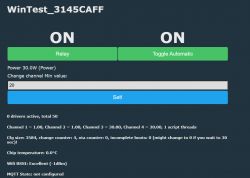
OpenBeken can be used to create simple automations involving multiple devices without Home Assistant. No central server is required, you only need to have flashed Tuya devices. Here I will show you one such automation, where two devices are used - first is a power meter, used to measure the power usage of device, and second is a relay used to turn cooling on and off. Cooling will be enabled when power usage is above given threshold.
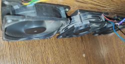
This simple setup is required for my DIY laptop cooling tab, as shown here:
Will a DIY cooling stand made from 12V fans help with laptop overheating?
First, let us consider requirements:
- cooling will be used in simple on/off mode, no PWM adjust yet
- first device will only measure power usage and send it to second device
- second device will offer automatic or manual modes, in automatic mode it will compare power with given threshold and enable relay if threshold is exceeded
The same could be done with a more reliable temperature measurement if needed.
Now let's first consider the available hardware.
- laptop is cooled by fans which are run at 5V currently. This is important information, because it will be used to simplify circuit later
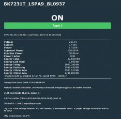
- LSPA9 plug measures power usage:
- a DIY device controls the power of fans, this device can run directly on 5V power, no mains required
Short introduction
OpenBeken runs currently on many various WiFi modules. Those modules can be easily then connected to Home Assistant, but it is not necessary for simple automations. OpenBeken supports scripting system via LittleFS, here you can view some sample scripts. For more info, see our documentation:
https://github.com/openshwprojects/OpenBK7231T_App/blob/main/docs/README.md
DIY device for fans control
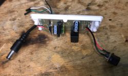
My current fans don't work well with PWM, so I decided to go for relay instead. In the future, I may introduce PWM control as well, but now I just needed a basic ability to toggle them on and off. That's why I decided to convert broken 230V relay control to 5V:
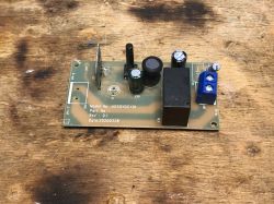
Following switch module has a simple, mains-powered step down converter that provides 5V for the relay, which is later fed to 3.3V LDO that powers WiFi module.
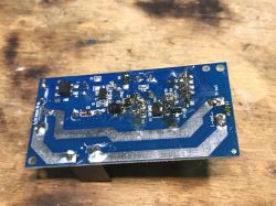
In case of powering whole circuit from 5V, the first 230V to 5V step down converter is not needed, but remember that voltage higher than 5V may just burn the 3.3V LDO and the WiFi module. If you want to use 12V, a 12V to 3.3V step down converter is required.
Final circuit:
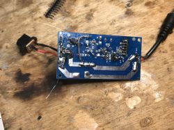
I have also replaced full bridge rectifier with a simple diode, as the DC is here already at the input, and the extra diode is only used for reverse-polarity protection.
DHT11 routed out for later experiments:
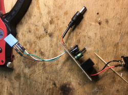
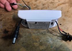
Case:
Setup for power measurement
LSPA9 was already flashed, it only needed a script to report power usage to target device.
I've decided to do it via HTTP GET command with Tasmota-style syntax:
again:

SendGET http://192.168.0.111/cm?cmnd=setChannel%202%20$power
delay_s 0.5

goto again
Make sure that IP of the target device is correctly entered in the script, also make sure that it won't change (do MAC reservation on router).
This basically sends the channel setting command:
setChannel 2 $power
and the $power is expanded to current power value from BL0937.
Setup for relay device
Relay device will have a bit more advanced script.
I would like script to offer two modes:
- automatic mode, where relay is set automatically to open or closed, depending on current reading and given margin
- manual mode, where user can control relay freely.
Futhermore, I would like the margin to be configurable on device GUI.
Luckily all that is possible with OBK channel types:
https://github.com/openshwprojects/OpenBK7231T_App/blob/main/docs/channelTypes.md
Let's start writing script by deciding the channels we need:
// main relay
setChannelType 1 Toggle
setChannelLabel 1 Relay
// working mode
setChannelType 2 Toggle
setChannelLabel 2 Automatic Mode
// received power [W]
setChannelLabel 3 Power
setChannelType 3 Power
// min power to enable cooling
setChannelType 4 TextField
setChannelLabel 4 Min Power To Cool
It might be also worth to save those channels in flashvars, so they are kept between reboots:
// remember channels
setStartValue 1 -1
setStartValue 2 -1
setStartValue 3 -1
setStartValue 4 -1
Now, we need to implement the main logic... the relay must be set to the value determined by the relation of given threshold and current reading. This must be done often, like every second or so, maybe 10 seconds... luckily it turns out it can be done with few lines:
again:
if $CH2==1 then setChannel 1 $CH3>$CH4
delay_s 1
If channel 2 is 1 (if mode is automatic), then set relay channel to the result of margin and value comparison. If channel 3 is larger than 4, it will yield 1, thus turning relay on.
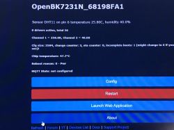
And here is the OBK panel for this script:

Using temperature sensor instead of the Power
Power usage may not be the best indicator for the cooling requirement, but the shown script can be simply adjusted to use measured temperature instead. OpenBeken supports DHT series of sensors, DS18B20 should also run correctly, so if you store temperature in channel 3, the same logic that works for power can now work for temperature. No futher changes in script are required.
Testing the automation script with OpenBeken Simulator
This section is not mandatory, it's just a recommendation for developers.
OpenBeken features an IoT device simulator that comes with automatic self test system. Self tests are used to make sure that each build does not breaks compatibility with expected OBK features and behaviours set.
Self tests are run automatically on Github with each online build.
Here's the self test I designed:
Code: C / C++
The following code setups the mentioned script inside the simulator and then simulates different use case scenarios, first the scenario with automatic control off, and then the scenario with automatic control on. It also simulates random power reading and verifies if the relay behavious is as expected. All expected OBK states are asserted with ASSERT preprocessor macros. If given assertion fails, then SelfTests are stopped with error, so a developer can check what's wrong.
The selftest mechanism is very useful because it allows us to quickly check if the new changes are working as expected. Selftest will fail if any of the new commited changes is breaking some of old features that are covered by self tests.
Selftests can run also on your PC, just like mentioned OBK Simulator.
Summary
This way you can make a very simple thermostat-like behaviour, with either just one or even two separate devices. The thermostat can be easily toggled on and off and the threshold value is also available on GUI.
If you need more advanced solution, you can also consider
creating custom driver.
That's all for now, but in the next part I'll show a similiar mechanism, but with PWM (gradual) cooling support. This will be used to reduce fan noise when strong cooling is not needed.


Comments
just in about six months I will have to put the whole iot in the new house, so I am thinking of getting rid of HA completely as an automation element - I would leave it possibly only for log collection... [Read more]
In OBK you can either use off-the-shelf support Tasmota Device Groups (for grouping lights, switches and lights, etc) or script SendGET queries so that devices directly "talk" to each other. You... [Read more]