logo elektroda
logo elektroda
X
ADVERTISEMENT
Treść została przetłumaczona polish » english Zobacz oryginalną wersję tematu
📢 Listen (AI):
  • ADVERTISEMENT
  • #332 21640074
    piotr_go
    DIY electronics designer
    Is it about 3:05?
    Hmmmmmmm, maybe some bug in the min/max image line limits....

    I've been busy with something else lately. When I find some spare time and finish the cache (I have a save left to correct), I'll look for the bug.
  • #333 21640089
    Jaz911
    Level 5  
    Yes, distortion at the bottom.
    Thanks, that would be great.
  • ADVERTISEMENT
  • #334 21643999
    Jaz911
    Level 5  
    Please help. I have assembled the board, it boots up.
    But there is no picture from the TV (old Sony Bravia), it displays a message that the format is not supported.
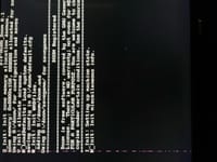
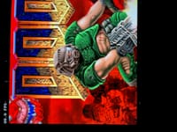
    Only DOOM comes out, but purple dots appear on the screen, and the board runs unstably, crashes and reports a memory allocation problem on reboot.
    I checked the power supply, the noise is about 3-5 mV, the generator pulse shape is perfect.
    I have flushed the flux several times. The memory is standard, -5I.
    What could be the cause?
  • #335 21644020
    piotr_go
    DIY electronics designer
    Jaz911 wrote:
    But there is no picture from the TV (old Sony Bravia), it displays a message that the format is not supported.
    .
    Which core?
    The menu is displayed?

    Jaz911 wrote:
    Only DOOM comes up, but purple dots appear on the screen and the board runs unstably, crashes and reports a memory allocation problem on restart.
    I checked the power supply, the noise is about 3-5 mV, the generator pulse shape is perfect.
    I have flushed the flux several times. The memory is standard, -5I.
    What could be the cause?
    .
    Where did you buy the memory and fpga? As long as not aliexpress/ebay/....
  • #336 21644042
    Jaz911
    Level 5  
    There is no picture on the TV, on all cores, except Risk-V (Doom).
    The menus work fine, all cores and firmware were installed with no problems.
    The chips were in place; I can't remember where I bought them, but they look fine....
  • #337 21644049
    piotr_go
    DIY electronics designer
    Jaz911 wrote:
    Microchips were available, can't remember where they were bought, everything looks ok...
    .
    Aliexpress/ebay sellers like to falsify markings.

    Have you checked on another TV?
  • #338 21644167
    Jaz911
    Level 5  
    I have not tested it on another TV.
    I'm more concerned about DOOM hanging, unstable performance and image noise.
    Should I change the FPGA?
  • ADVERTISEMENT
  • #339 21644176
    piotr_go
    DIY electronics designer
    Jaz911 wrote:
    Change the FPGA?
    .
    Not yet.

    Isn't there some shorting of the HDMI pins? Maybe something is not making contact.
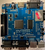
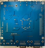
    Post a picture of the noise and the PCB from both sides.

    The SD card can cause DOOM to be unstable.
  • #341 21644280
    piotr_go
    DIY electronics designer
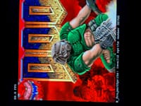
    This image interference looks more like an HDMI problem.
    Check the HDMI connector with a meter for a short circuit to ground and between adjacent pins somewhere.

    Generator definitely 18.432MHz ?

    "Invalid sprite number" is probably a communication error with the SD card. Maybe it's not making it to the set frequency, or there's an error in the code to the SD.
  • #342 21644289
    Jaz911
    Level 5  
    Yes, the generator is correct (KC3225A18.4320C3GE00), checked with an oscilloscope.
    Apart from the noise on the screen, doom does not work, crashes :( .
    I will check the connector for short circuits, write.

    UPDATE: I have checked the HDMI connector, there are no short circuits.
  • #343 21644309
    Macosmail
    Level 35  
    Check on another TV. On my one old Panasonic plasma TV on the amiga core there was no picture either.
  • ADVERTISEMENT
  • #344 21644327
    piotr_go
    DIY electronics designer
    In my case 90% of the problems after soldering were HDMI socket short circuits. Sometimes the FPGA shorted out.
    It also happened that everything looked OK and didn't work as expected. It turned out that one of the FPGA pins was not connecting to the pad.

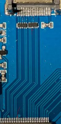
    Close-up of PCB with red marks indicating suspected solder shorts near HDMI and pins .
    I've highlighted the suspect areas in red.

    Without checking on another TV I can't think of anything else.
  • #345 21644352
    Jaz911
    Level 5  
    I've checked again, everything is correct, but I'm in a blind spot.
    I'll try it with another TV and another SD card.

    UPDATE: If the problem is not compatible with my TV, why is Doom displaying the image?
  • #346 21644356
    piotr_go
    DIY electronics designer
    On the FPGA side, did you also check for shorts between adjacent pins?
  • #347 21644370
    Jaz911
    Level 5  
    Yes, everything is fine on the FPGA side, I have just checked again.
  • #348 21650696
    Jaz911
    Level 5  
    I soldered the suspect areas and washed thoroughly.
    There are some improvements, but I noticed that the stability of operation depends on the temperature.
    When the board is cold, it boots without any screen noise and Doom runs, when it gets hot, after a minute it crashes and stripes appear.
  • #349 21651209
    piotr_go
    DIY electronics designer
    I think you will have to change the FPGA.

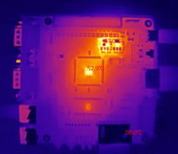
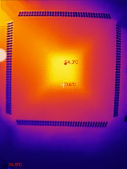
    After 20 minutes of DOOM:
    Thermal image of an FPGA board showing temperature spots of 67.0°C, 52.9°C, and 28.0°C. .
    Thermal image of an FPGA showing a peak temperature of 54.3°C after 20 minutes of DOOM gameplay. .
  • #350 21656987
    Jaz911
    Level 5  
    I replaced the FPGA, now everything is fine.
    DOOM is running without problems, stable.
    Thanks for your help!

    P.S. Works with RISC-V 0.4.1, crashes on 0.4.
  • #351 21658260
    piotr_go
    DIY electronics designer
    Well, that's great.
  • #352 21693220
    tsobieraj
    Level 2  
    sillycon wrote:
    I have soldered some of the ports.
    By any chance are the menu and reset switched places? When I click the menu button while in the menu, the reset occurs. Is it possible that something is connected incorrectly?
    Edit: The reset works after uploading the core - it only resets the current core. So it is ok.

    I thought the kickstart and hdfs were supposed to be on the SD card? Do you still need to upload something to flash to boot?
    Edit2: ok got it, on yt dasamo123 has a video after watching which everything seems clearer.
    Edit3: all clear, I have uploaded mikan 0.1.5 and KICK13.ROM and KICK31.ROM, but the screen with the Amiga floppy does not appear. Either a white screen on 1.3 or a black screen on 3.1. Did I choose the right core?

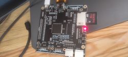
    DIY-A586 PCB board with SD card and HDMI cable. .

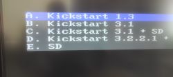
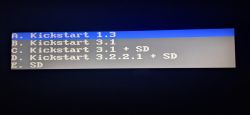
    Kickstart selection menu on screen with options A to E.

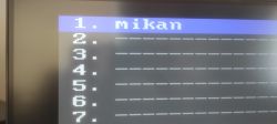
    Environment selection menu with mikan as the first option. .

    Once I get this sorted out, I can warp the kickstart and start installing.


    Hey, I just became the owner of the board and I have a question about the menu with the selection of Kickstarts for Amiga - A/B/C/D.

    Amiga Kickstart selection menu with five options labeled A to E, each listing a version name. .

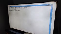
    Namely, are the names and associated roms somehow editable? Only selection D works, with C I have this view:

    Amiga screen showing MakeLink failed returncode 20 error. .

    On the other hand, I have Kickstart 3.2.3 and wanted to try to get it working here.

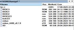
    I have the Kickstart names named like this:

    Screenshot of a folder containing several Amiga Kickstart ROM files .

    Thanks to
  • #353 21693243
    piotr_go
    DIY electronics designer
    tsobieraj wrote:
    Only selection D works, with C I have this view:
    .
    So it works. The system apparently only works with 3.2

    You can edit the kickstart with some hexedit. The last 4kB of the *.D19 file.
    I didn't do the editor unfortunately. In the plans...

    I attach the core with the change (not tested, cut ".bin" from the name).
  • #354 21693551
    Jaz911
    Level 5  
    Hi Piotr,
    Another question: are there any differences in the FDD controller implementation compared to the original Amiga/Paula?
    Will I be able to read 1.44 MB MS-DOS floppy disks in Workbench?
    My floppy drive is standard HD 1.44.
  • #355 21694168
    piotr_go
    DIY electronics designer
    I just added an auto switch. As there are 2 stations, the one with the current floppy is set as DF0 during reset.
    1.44M on the station from the PC will not work. Maybe the original Amiga HD station, but I don't have one to check.
📢 Listen (AI):

Topic summary

The DIY-A586 v1.9 is a Spartan6 XC6SLX9 FPGA-based Amiga-compatible board featuring 32MB 16-bit SDRAM, 16MB flash memory, HDMI output, analog audio with tape input, SD card slot, RS232, dual joystick and PS/2 ports, A500 keyboard connector, floppy disk drive connectors, USB-C 5V power, and onboard buttons and LEDs. It supports up to 30 FPGA configurations loaded from flash. The core uses a TG68 CPU softcore similar to Minimig but with a custom chipset and own implementations. Memory timing requires 133MHz/CL2 SDRAM, with Winbond W9825G6KH-5 or -6 compatible but untested variants. The project includes Amiga ROM patches and SD card ROM loading; flash must be formatted and programmed via menu. Floppy drive compatibility requires PC drives converted to Amiga standard with RDY signal generation. The board supports multiple cores including Amiga (Mikan core), NES, Spectrum, and RISC-V, with paid registration for some cores. Users report issues with floppy reading on Kickstart 1.3 fixed in core v0.1.6. Audio over HDMI requires timing adjustments due to resolution constraints. The project is open for community assembly with parts sourced from AliExpress, LCSC, Digikey, and Mouser, with suggestions for alternative components like AMS1117 regulators and 74AHCT logic ICs. Future plans include version 2.0 with larger FPGAs (Cyclone 4) and AGA + 68020 support, but no immediate release. The community discusses soldering order, flash programming, and component sourcing, with some users sharing build experiences and troubleshooting tips. The project emphasizes fast Workbench operation, real floppy drive support, and HDMI output as advantages over Minimig. Source code for the Mikan core is not publicly shared, but spectrum core sources are available. The board is suitable for advanced hobbyists with SMD soldering skills and FPGA experience.
Summary generated by the language model.
ADVERTISEMENT