logo elektroda
logo elektroda
X
logo elektroda

[BK7231N - CB3S] Generic Tuya Wall Switch Push Button Type 1-3 Gang No Neutral

ferbulous 12684 71
ADVERTISEMENT
  • #61 20616601
    p.kaczmarek2
    Moderator Smart Home
    Both Tasmota Device Groups and SendGet commans can be effectively used to control another device remotely. You can even do something like "quadruple click turns off all lights in the house" and just use a script thread (maybe with delay_s) to send multiple GET requests with POWER OFF to many devices.
    Helpful post? Buy me a coffee.
  • ADVERTISEMENT
  • #62 20617083
    jrhenk
    Level 10  
    Thanks for the additional info... could be interesting to look into devices controlling each other directly without home assistant. Would really have to document that somewhere very well since I can already see me tearing my hair out how I did this when it doesn't show up in HA and I want to change something one year from now :)
  • ADVERTISEMENT
  • #63 20694752
    jkwim
    Level 12  
    jrhenk wrote:
    With this new freedom of the LEDs not being used as a trigger anymore, I could even do a silly thing and code a little animation with the three leds... when I have reconfigured the switch next to it in the same way, I could do an animation across the 6 buttons leds of the two switches


    You gave me an idea. I am also going have 2 x 3 gang switches in a row. I was looking at way of implementing a timer with 5 or 10 steps with visual or audible feed back as to number of steps set. Perhaps the LEDs can be used during timer settings to give visual feedback, 6 x LEDs x 2 colors = 12 steps?
  • ADVERTISEMENT
  • #64 20694801
    p.kaczmarek2
    Moderator Smart Home
    You can write a simple script in separate file in LittleFS and use delay_ms command and if and goto to create simple animations.

    Or I can write a driver for you, if that's needed.
    Helpful post? Buy me a coffee.
  • #65 20695210
    jkwim
    Level 12  
    jrhenk wrote:
    Thanks for the additional info... could be interesting to look into devices controlling each other directly without home assistant. Would really have to document that somewhere very well since I can already see me tearing my hair out how I did this when it doesn't show up in HA and I want to change something one year from now :)


    For the past 10 years+ I have been Microsoft OneNote as a digital notebook app (on Laptop and Mobile).

    All these litle tinkering I do gets documented in a OneNote page so that I can even revisit the task after several years and resume from there.

    Whenever I see some interetsing replies in these forums, I make it a point to cut & paste the tit bits in to OneNote. When I have some time free, I go back and orginize them with proper titles etc. It has helped me a lot over the years to keep a track.

    For example for each new type of device that I flash OpenBK, I create a new page. After a while everything about that device gets documented there. Text, images, my own photos, links, code samples, configutaions etc. get dumped there so that I know exactly where to look for that info.
  • #66 21001870
    dwildstr
    Level 4  
    I'm trying to flash (well, start by reading the flash) a device which I am pretty certain is near-identical under the hood to this one. It's an Aubess-branded one-gang no-neutral-required touch switch. , with a printed model number of DS-1211SL. It's got a six-pin header on the power-supply/relay board which mates with six pins on a board with a touch-sensor and CB3S board. It looks a lot like the DS-101, although the MCU is mounted "upside-down" -- the metal shielding with a QR code is visible, instead of the printed pin labels and bulls-eye. I've cut the trace from pin 16 of the touch-control IC to RXD1, which seems to be generally necessary based on conversation here. I have a kind of janky setup with headers on the GND and VCC pins, a loose branched ground wire to brush against CEN, and dupont pins which I physically hold against the TXD1 and RXD1 points while flashing. It does seem to actually communicate, but I'm getting some failures. First, a successful result, from just trying to talk to the chip at all:

    
    $ ltchiptool flash info -d /dev/ttyUSB0 BK7231N
    I: Connecting to 'Beken 7231N' on /dev/ttyUSB0 @ 115200
    I: |-- Success! Chip info: None
    I: Reading chip info...
    I: Chip: None
    I: +--------------------+---------------------------+
    I: | Name               | Value                     |
    I: +--------------------+---------------------------+
    I: | Chip Type          | Unrecognized (0x9671FEB5) |
    I: | Bootloader Version | Unspecified               |
    I: | Protocol Type      | BASIC_BEKEN               |
    I: +--------------------+---------------------------+
    I: |-- Finished in 0.076 s


    That seems right, but trying to read produces an early error:
    
    $ ltchiptool flash read -d /dev/ttyUSB0 BK7231N test-image
    I: Connecting to 'Beken 7231N' on /dev/ttyUSB0 @ 115200
    I: |-- Success! Chip info: None
    I: Reading Flash (2 MiB) to 'test-image'
      [----------------------------------------------------------------]    0%  00:0
      [----------------------------------------------------------------]    0%  00:0
      [----------------------------------------------------------------]    1%  00:03:10
    E: ValueError: Chip CRC value 41F76468 does not match calculated CRC value FC74788D (at 0x0)
    E: |-- File "/home/dwildstr/.local/pipx/venvs/ltchiptool/lib/python3.11/site-packages/ltchiptool/soc/bk72xx/flash.py", line 234, in flash_read_raw


    Running ltchiptool with the "-C" option keeps it from failing, and pulls 2 megabytes off in 193 seconds, but trying to use bk7231flasher's config extraction tool on it gives the error "Failed to extract Tuya keys - magic constant header not found in binary" when run on the result.

    I want to read before trying to write, because (a) it's a nondestructive test of the system, and (b) I want to pull the Tuya config out, just in case this particular model uses atypical GPIO mappings. I hope I'm making a simple dumb error here --- I rarely do serial flashes, and have never physically flashed a Tuya MCU before, just ESP8266s and ESP32s, so I'd welcome the news that there's an easy way to fix the problem I'm having.
  • #67 21002240
    p.kaczmarek2
    Moderator Smart Home
    This device looks fairly simple, why do you need config extraction for that? You can as well just use OpenBeken GPIO Doctor to figure out the IO roles quickly.
    Helpful post? Buy me a coffee.
  • ADVERTISEMENT
  • #68 21002773
    dwildstr
    Level 4  
    I don't need config extraction, no, but if I'm going to be pushing new firmware to the device I'd like some certainty that I've got a good backup before I do that, and if I'm having corruption on reads (or whatever's going on here) it seems likely I'd also have corruptions of writes, and I'd rather fix problems when they're lower-impact. Config extraction is just a bonus.
  • #69 21002779
    p.kaczmarek2
    Moderator Smart Home
    Can you read 2MB flash with bk7231flasher, maybe try lower baud speeds?
    Helpful post? Buy me a coffee.
  • #70 21008117
    dwildstr
    Level 4  
    Trying default baudrate:
    
    Starting read!
    Now is: Sunday, March 17, 2024 1:27:29 PM.
    Flasher mode: BK7231N
    Going to open port: /dev/ttyUSB0.
    Serial port open!
    Getting bus... (now, please do reboot by CEN or by power off/on)
    Getting bus success!
    Going to set baud rate setting (921600)!
    Will try to read device flash MID (for unprotect N):
    Flash MID loaded: 1560EB
    Will now search for Flash def in out database...
    Flash def found! For: 1560EB
    Flash information: mid: 1560EB, icName: TH25Q_16HB, manufacturer: TH, szMem: 1000000, szSR: 2, cwUnp: 0, cwEnp: 7, cwMsk: 407C, sb: 2, lb: 5, cwdRd: 05-35-FF-FF, cwdWr: 01-FF-FF-FF
    Entering SetProtectState(True)...
    sr: 84
    sr: 4684
    final sr: 4684
    msk: 407c
    cw: 0, sb: 2, lb: 5
    bfd: 0
    sr: 80
    sr: 680
    final sr: 680
    msk: 407c
    cw: 0, sb: 2, lb: 5
    bfd: 0
    SetProtectState(True) success!
    Going to start reading at offset 0x00...
    Reading 0x00... failed with serial.BytesToRead 4095 (expected 4111)
    The beginning of buffer in UART contains 040EFF01E0FCF40610090000002000AA data.
    Failed! There was no result to save.


    Trying with a speed of 115200 baud produced the same results including the second-to-last line's listing of the buffer contents. The only differences in the log were the unsurprising replacement of "Going to set baud rate setting (921600)!" with "Going to set baud rate setting (115200)!", and the somewhat more mysterious replacement of "sr: 84" and "sr: 4684" with "sr: fc" and "sr: 46fc".

    Both attempts had the same result on the device itself and the FT232 programmer I was using: when the MCU was hooked up, an LED on the front was flashing, but connecting CEN with GND briefly made it go off. The communication up to "Reading 0x00..." was fast and accompanied by a flurry of fast blinks on the RX and TX lights of the FT232. The "Reading 0x00..." line was accompanied by a complete lack of light activity on the FT232, suggesting communication wasn't happening, which persisted for about a minute until the failure message came up.
  • #71 21451532
    rk125
    Level 1  
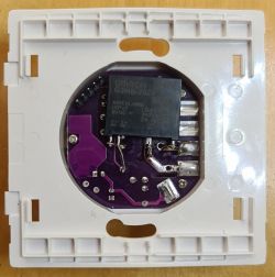
    To make switch quiet. With one relay it is pretty easy. SSR G3MB-202P, can get in packs of 5 in aliexpress, make sure it have 5V control voltage.
    View of an OMRON G3MB-202P electronic relay mounted on a PCB with a plastic base.
  • #72 21558911
    mvz0209
    Level 5  
    Please tell me, are there wifi control units without zero with relays, and not with triacs. To keep the load on, at least like this 600W switch? If yes, please send the link?

Topic summary

The discussion revolves around the Generic Tuya Wall Switch Push Button Type (No Neutral) featuring the BK7231N chip and CB3S module. Users share experiences related to flashing the device, troubleshooting configurations, and modifying the hardware. Various flashing methods, including OTA and serial connections, are discussed, with users providing insights on firmware versions, pinouts, and the potential for independent LED control. The conversation highlights the importance of identifying the correct firmware profile for successful flashing and the challenges faced when dealing with different models and configurations. Users also explore the possibility of repurposing GPIO pins for additional functionalities.
Summary generated by the language model.
ADVERTISEMENT