logo elektroda
logo elektroda
X
logo elektroda

FEIT Smart WiFi Light Strip - Model: FETAPE/RGBW/CNTRSC - FCC ID: SYW-TAPRGBWCNTRSC - 7231N

Wonko 10476 96
ADVERTISEMENT
  • #61 20558222
    rjfmn
    Level 2  
    The other part that's truly confusing to me is this:

    UART is a bi-directional bus, so first we capture from the TuyaMCU TX line -> WiFi RX module, and then from the WiFi line TX module -> TuyaMCU RX

    Is that one capture using TX1/RX1 and then another using TX2/RX2, I guess, then they're stitched together by the analyzer?
  • ADVERTISEMENT
  • #62 20558281
    p.kaczmarek2
    Moderator Smart Home
    They are not current stiched by analyser, as it's not needed. We just need to know dpIDs and content of packets, to determine which dpID has which role. That is enough to write autoexec.bat for OpenBeken to map TuyaMCU variables to obk channels.
    Helpful post? Buy me a coffee.
  • #63 20559417
    bobthemonkee
    Level 5  
    >>20558222

    Were you successful at capturing any data? If not, I might give it another shot.
  • ADVERTISEMENT
  • #64 20559680
    p.kaczmarek2
    Moderator Smart Home
    I would say please try to do the capture. Maybe we will learn something more.
    Helpful post? Buy me a coffee.
  • ADVERTISEMENT
  • #65 20565007
    rjfmn
    Level 2  
    >>20559417

    I haven't tried yet, as I'm still unclear on whether to use TX1/RX1 or TX2/RX2 to get the data we need.

    To be fair, I also haven't had any time to look at it.
  • #66 20711203
    plexusresort0a
    Level 3  
    >>20559680

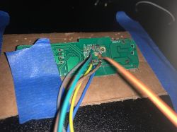
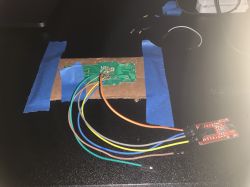
    I have a model of the FEIT Smart WiFi Light Strip that uses a TuyaMCU that I'm trying to get working with OpenBK. I'm trying to capture the packets with one USB to UART. (This is the part that I don't know if I'm doing correct) I connect my TX2 to RX and capture with RealTerm then I plug in ground and power and it starts reading stuff then I start a new capture turning off and on the led strip with the Smart Led Button on the device. I take the captures and put them into TuyaMCUAnalyzer and it outputs nothing.

    If anyone has guidance on getting these dpIDs that would be amazing.

    Thanks in advance,

    Close-up of a circuit board with connected colorful wires and secured with blue tape. Electronic circuit connected to a USB to UART module with wires.
  • #67 20711213
    p.kaczmarek2
    Moderator Smart Home
    Can you please show the data that you captured in HEX form?
    Helpful post? Buy me a coffee.
  • #68 20711684
    bobthemonkee
    Level 5  
    >>20711203

    Awesome to see some progress on this! Please keep this thread updated. I have 4 of these I'd love to get working!
  • #69 20712096
    plexusresort0a
    Level 3  
    >>20711213

    Here is the hex i get powering on the device

    F80052F35756FFC77795567F63E353161F109F560146C3F26BFB1B579FEB8B5607F37610127272561082FB4B5642EA86EF9EEEEA131C15145A5A1A145A5A5AEB0210EB537BD7102767D36B1013EF56E793DF62C212C310101356E76B7F1227F7535610177310C215F2EA8190736A428556E7637A436212C21156E763EB7F5A760BFB7F5A763BFB

    I tried capturing the on and off of the lights with the Smart Led Button but that isn't returning anything
  • #71 20715687
    p.kaczmarek2
    Moderator Smart Home
    plexusresort0a wrote:


    F80052F35756FFC77795567F63E353161F109F560146C3F26BFB1B579FEB8B5607F37610127272561082FB4B5642EA86EF9EEEEA131C15145A5A1A145A5A5AEB0210EB537BD7102767D36B1013EF56E793DF62C212C310101356E76B7F1227F7535610177310C215F2EA8190736A428556E7637A436212C21156E763EB7F5A760BFB7F5A763BFB

    Sorry but it doesn't look like anything meaningful. Please do a capture at both baud rates (first try 9600, then 115200) and check the UART content repeatedly, try to parse it with analyzer:
    https://github.com/openshwprojects/TuyaMCUAnalyzer

    TuyaMCU will contains headers like 55 AA etc which I can see is totally absent from the data you posted.


    We really need UART data capture for this device.
    Helpful post? Buy me a coffee.
  • #73 20718322
    p.kaczmarek2
    Moderator Smart Home
    It looks like something that could work with tuyaMcu_setupLED.

    Can you please do, maybe, one more test?

    I want separate captures for:
    - setting 100% red color
    - setting 100% green color
    - setting 100% blue color

    Then we can use the search button:
    https://www.elektroda.com/rtvforum/find.php?q=tuyaMcu_setupLED

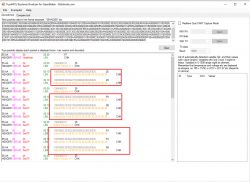
    It also seems that dpIDs are matching the standard ones. For example:
    Screenshot from TuyaMCU Explorer/Analyzer showing raw and decoded packet data.
    dpID 24 is a color data in a form of a string
    Helpful post? Buy me a coffee.
  • #75 20719558
    p.kaczmarek2
    Moderator Smart Home
    Blue is:
    
    55 AA	00	00		00 00		FF	
    HEADER	VER=00	Heartbeat		LEN		CHK	
    
    55 AA	00	06		00 05	1504000101	25	
    HEADER	VER=00	SetDP		LEN	fnId=21 Enum V=1	CHK	
    
    55 AA	00	06		00 10	1803000C303066303033653830336538	32	
    HEADER	VER=00	SetDP		LEN	fnId=24 Str V=30 30 66 30 30 33 65 38 30 33 65 38	CHK	


    In ASCII: 00f003e803e8
    When you search for it on our forum:
    https://www.elektroda.com/rtvforum/find.php?q=00f003e803e8
    it leads to @nethawk 's topic, so we're home....

    Green is:
    
    55 AA	00	06		00 05	1504000101	25	
    HEADER	VER=00	SetDP		LEN	fnId=21 Enum V=1	CHK	
    
    55 AA	00	06		00 10	1803000C303037383033653830336538	0B	
    HEADER	VER=00	SetDP		LEN	fnId=24 Str V=30 30 37 38 30 33 65 38 30 33 65 38	CHK	
    

    In ASCII: 007803e803e8
    It's also on our forum:
    https://www.elektroda.com/rtvforum/find.php?q=007803e803e8
    It has the same protocol, it seems.

    You can flash OBK now, but of course, make 2MB backup of original firmware.
    Helpful post? Buy me a coffee.
  • #76 20721656
    bobthemonkee
    Level 5  
    Excellent! With the info from the other threads, I was able to get white, red, blue, green working properly. Here was the autoexec.bat I used.

    Couldnt get simulated cool white to work via main interface

    startDriver SSDP
    startDriver TuyaMCU
    tuyaMCU_setupLED 24 0
  • #77 20756015
    tankdeer
    Level 4  
    Hi there, sorry for the noob question, but I can't get this to work. I have the same strip as you, confirmed the chip & same firmware version. I was able to flash it via cloudcutter without too much trouble, but nothing I do (besides the button) gives me any light output. I was excited when I saw you had figured it out, but upon importing this autoexec.bat, there doesn't seem to be any change. It gives me a list of effects, and the main UI has toggle/color options, but they have no effect. And it doesn't have any pin configurations. Am I missing something? It feels like I overlooked a step but I am not sure where. I've gone through and manually changed pin settings several times and nothing.

    Any help you can give would be greatly appreciated.
    Thank you
  • #78 20756032
    bobthemonkee
    Level 5  
    Sorry about that, I need to post my updated config. I will fix this in a couple of hour when I'm home!
  • ADVERTISEMENT
  • #79 20756098
    tankdeer
    Level 4  
    That would be fantastic. This has been driving me nuts. Thank you so much
  • #80 20756236
    bobthemonkee
    Level 5  
    Use this in your autoexec.bat as bare minimum to get it working. Lemme know if you have any issues!

    I was not able to get scenes working yet, so this will at least get you up and running.

    startDriver TuyaMCU
    tuyaMCU_setupLED 24 0
  • #81 20756244
    tankdeer
    Level 4  
    Wow, thank you so much. Yes, that got it working - I knew it must be something simple. I honestly don't care about the scenes so just having the bare minimum is OK with me.

    Thanks again
  • #82 20756422
    p.kaczmarek2
    Moderator Smart Home
    The setupLED currently uses some of the hardcoded dpIDs, soon we will make them configurable, but still, command most likely will be able to use default settings as well.
    Helpful post? Buy me a coffee.
  • #83 20764706
    tankdeer
    Level 4  
    So the only other thing I'd like to get working is the button. With the default settings above, it does toggle the light on/off as expected, however it does not report that to the UI or Home Assistant.

    I played around a little and discovered that the power toggle was dpID 20, so I tried the following:

    setChannelType 20 toggle


    Then it appeared I needed to link that to a channel, so I added

    linkTuyaMCUOutputToChannel 20 1 20


    That got it working in a way. It created a separate toggle for channel 20 (After I set the type in the web app), and that was updated when I pressed the button. Obviously that is not ideal, as I would like to update the existing 'Light' that was created with the default config.

    So my question is how do I link dpID 20 to the current light with the default config? I am thinking the above steps are not correct for this light, but I could not find anything in the documentation that pointed me in the right direction.

    Thanks
  • #84 20782933
    tankdeer
    Level 4  
    Hey everybody. Don't mean to be a pest, but wanted to follow up and ask if anybody knows how to get the physical button to update the light's state in the firmware and Home Assistant? It does physically turn the light on/off, but HA is unaware of it and still thinks it's off. See previous post for some more details.

    Thanks
  • #85 20783206
    p.kaczmarek2
    Moderator Smart Home
    Oh I see, I am sorry, it seems that I haven't seen your message before.

    Our code is indeed only sending dpID 20 for now, not sending.

    I can add a receiving support for you.

    Just to confirm, in your current situation, the HA can turn on and off the lamp, but if you press physical button on the device, the change does not propagate back to HA?
    Helpful post? Buy me a coffee.
  • #86 20783669
    tankdeer
    Level 4  
    p.kaczmarek2 wrote:
    Oh I see, I am sorry, it seems that I haven't seen your message before.

    Our code is indeed only sending dpID 20 for now, not sending.

    I can add a receiving support for you.

    Just to confirm, in your current situation, the HA can turn on and off the lamp, but if you press physical button on the device, the change does not propagate back to HA?

    Yes, that is exactly it. Thank you so much - that will be very helpful
  • #87 20783699
    p.kaczmarek2
    Moderator Smart Home
    Ok @tankdeer , here's my idea for the solution:
    https://github.com/openshwprojects/OpenBK7231...mmit/5f66f0b25e7d42ded69b7a430c8a7276319358c0
    I am not sure if it works, can you update and check?
    Helpful post? Buy me a coffee.
  • #88 20783719
    tankdeer
    Level 4  
    That seems to work perfectly. Thank you so much for the quick turnaround. I will flash this on my other devices and let you know if there are any issues
  • #89 20783730
    p.kaczmarek2
    Moderator Smart Home
    Ok, thanks for testing. Is there anything else I may add for you?

    PS: Keep in mind that you can submit any device teardown to our forum both IoT teardowns, here: https://www.elektroda.com/rtvforum/forum507.html and non-IoT, here: https://www.elektroda.com/rtvforum/forum519.html
    Helpful post? Buy me a coffee.
  • #90 20783736
    tankdeer
    Level 4  
    I have been using it for a few weeks now and the power button was the only thing I noticed that was missing. Thanks again for all your work.

Topic summary

The discussion centers on the FEIT Smart WiFi Light Strip (Model: FETAPE/RGBW/CNTRSC, FCC ID: SYW-TAPRGBWCNTRSC, chipset BK7231N) and its integration with OpenBK firmware and Home Assistant (HA). Key points include the necessity of using the native interface over the web app for proper RGBW (warm white) control, requiring flag 24 to correctly handle the RGBW channels as a single light rather than separate lights. Pin assignments for PWM channels and the smart button (pin 26) were identified, with PWM pins 6, 7, 8, and 9 mapped to PWM4 (warm white), PWM2 (green), PWM1 (blue), and PWM0 (red) respectively. Firmware updates fixed earlier issues with flag 24 and HA discovery.

The thread also covers challenges in flashing and debugging the BK7231N chip, including damaged diagnostic pads and the need for external probes. Users shared methods for flashing via Raspberry Pi UART and Cloudcutter, and discussed the use of TuyaMCU for devices with additional MCU chips, including capturing UART data to identify dpIDs for LED control. The TuyaMCU setup command and autoexec.bat configurations were shared to enable LED color control and button functionality.

Further discussion addressed Home Assistant integration, specifically the handling of color temperature ranges (Mired and Kelvin units), with the introduction of the CTRange command to set min/max Mired values for accurate adaptive lighting support. The web app's YAML generator was deprecated in favor of HA discovery, which now supports 4 PWM channels with the simulate white flag.

Issues with the physical smart button not updating HA state were resolved by adding firmware support for receiving dpID 20 toggle events, enabling state synchronization between the device and HA. Users also reported improved WiFi performance and local control responsiveness with OpenBK firmware compared to native Tuya firmware.

Additional troubleshooting involved devices with different hardware configurations, including those with extra chips requiring TuyaMCU communication, and the need for UART packet captures to map dpIDs. The community shared resources such as BK7231 datasheets, pinouts, and firmware repositories to assist in device configuration and flashing.

Overall, the discussion provides detailed technical guidance on flashing, configuring, and integrating the FEIT Smart WiFi Light Strip with OpenBK firmware and Home Assistant, addressing PWM pin mapping, flag settings, TuyaMCU integration, color temperature handling, and button state synchronization.
Summary generated by the language model.
ADVERTISEMENT