logo elektroda
logo elektroda
X
logo elektroda

[BK7231N / T34 ] Teardown Tuya Generic Wifi Wall Light Switch 3 Gang

CameronDev 19425 99
ADVERTISEMENT
  • #31 21031898
    rufus4
    Level 10  
    I have problems to readout original tuya fw from the T34.
    After a while it stops reading with error.
    Is there some special settings to manage readout?
    Screenshot of a firmware reading program with a Reading failed message.
  • ADVERTISEMENT
  • #32 21031906
    p.kaczmarek2
    Moderator Smart Home
    You can try playing around with values in "UART timeouts" tab, you can also shorten your wires. Alternatively, you can use python solution for BK7231N, follow this tutorial:


    Added after 15 [seconds]:

    https://github.com/OpenBekenIOT/hid_download_py
    Helpful post? Buy me a coffee.
  • #33 21032083
    rufus4
    Level 10  
    Thanks again for your help!
    Playing arround with baud rate didn`t help. Somehow the problem was the lab power supply. Now with a cheap chinese one I could read out flash.

    Is the log entry "Failed to extract Tuya keys - no json start found" relevant?
    Could it be that Tuya json does not exist because it was not created while device is still "virgin" and never got configured before?[/code]
  • ADVERTISEMENT
  • #34 21032342
    CameronDev
    Level 4  
    I got something similar when trying to extract the json from my firmware, I had to manually create the config. There is still a json config that can be found in the firmware dump, so you can try read it manually.
  • #35 21041208
    Tilator
    Level 10  
    t2004dd wrote:
    I flashed T34 chip successfully.
    Bridge CEN is not needed. You can start flashing if you just interrupt 3.3V , attached to the PIN8.
    I flashed it with baud rate 921600.

    BK7231N chip with soldered wires on a white surface.
    Electronic module with green screw terminal block and black relay on a PCB.


    Did you flash it using BK7231N flash file and procedure? Are T34 and BK7231N identical enough? Except different pinout.
  • #36 21041261
    p.kaczmarek2
    Moderator Smart Home
    Yes, you need to use BK7231N procedure.

    Please refer to the following videos to see details of BK7231 flashing:
    Using https://github.com/openshwprojects/BK7231GUIFlashTool


    Using https://github.com/OpenBekenIOT/hid_download_py


    Helpful post? Buy me a coffee.
  • #37 21043972
    aliexpress
    Level 4  
    @karayoooo : I have the same T34 based SmartPlug with Energy measurement. I was able to connect wires and flash it successfully. By the way, it was not necessary to remove the 10K resistor which connects to P26. It worked leaving it in.

    However, the .bin file analysis did not give me a JSON config from the original firmware (key error just like others experienced).
    @karayoooo : Can you please provide your JSON config for this device? I did not yet manage to reverse engineer the pin settings :-(

    Added after 1 [hours] 58 [minutes]:

    So far I found out:
    "pins": {
    "6": "BL0937CF;0",
    "7": "BL0937CF1;0",
    "8": "BL0937SEL;0",
    "24": "Rel;1",
    "26": "Btn;1"
    }

    There are several LEDs behind the Button. One is coupled directly with the Rel and turns on/off together with Relais.
    There is a 2nd less bright one. I guess this could be used for WiFiLED... Pin assignment yet unclear....
  • #39 21044684
    aliexpress
    Level 4  
    Thanks rufus, yes, it is exactly the device as in the link, and the additional WiFi Led is working on P28!
  • #40 21044802
    Tilator
    Level 10  
    karayoooo wrote:
    Hello guys

    it can be done directly without unsoldering T34.
    Here in a tuya socket.
    Yes It's tricky and yes a pcb pad is quite (but not) broken but it works !

    Close-up of a circuit board with an integrated circuit and a missing capacitor marked as C1.


    It seems to lack one component (C1). Does it work without it or did you put it back?
  • #41 21049093
    dhanushkadx
    Level 5  
    The image shows a blue printed circuit board with a detached SMD component next to it. Close-up of a blue circuit board with an SMD chip mounted on it. Printed circuit board with mounted SMD components. Screenshot of BK7231N flashing software on a computer. Electronic tools and circuit board on a blue workbench. PCB with SMD components, BGA flux, and tweezers on a blue background. Touch switch with a visible circuit board and packaging. Computer screen displaying the OpenBK7231N configuration interface. Screen of OpenBK7231N_E1E779B1 configuration with module setting options.

    This is not impossible if you have some smd chip reworking skills. actually this is my second switch . pervious one also succeeded. I used little flux and 400C hot air, be careful if u heat it too much pcb will be fried .
  • ADVERTISEMENT
  • #43 21049681
    dhanushkadx
    Level 5  
    Blue electronic module with a USB plug and small integrated circuit. Red USB signal conversion module with labeled pins and a voltage selection jumper.

    I use the red module. blue module also ok. set vcc jumber to 3.3V . and do not connect vcc line to chip untill the programmer start to flash. first press flash button of itchip tool or what ever after that connect vcc to ic . you may have to do this a few times to get it on flash mode
  • #44 21049682
    ferbulous
    Level 18  
    @dhanushkadx did you still need to apply some solder paste or is it just flux? Also, how long do you apply the hot air to the chip
  • #45 21049685
    dhanushkadx
    Level 5  
    its flux that is a chemical to prevent oxidation . I used 400 c air it took me less that a 60 seconds to lift the chip. there are technics to bring down the heating time much further . if u use a pre heating machine you can bring pcb temp to 150 so it will take about 20 seconds to lift the chip. watch some youtube videos if you haven't rework a smd chip ever. because if you apply hot air longer there is a risk of damage the chip or pcb. SMD chip reworking is a skill that u should improved . sometimes i also burn chips mistakenly . get some old pcb with smd chip and try to rework before you do that to the working pcb.
  • #46 21049686
    ferbulous
    Level 18  
    @dhanushkadx sorry, i meant for when you’re soldering back the chip to the pcb.
    So should be around the same time (<60 seconds) with some solder paste?
  • ADVERTISEMENT
  • #47 21049694
    dhanushkadx
    Level 5  
    approximal the same time(60 sec) . regardless of removing or reordering the chip, its very important to give some breathing time to the pcb like 2 seconds for every 5 seconds of hot air . it allows to spread the heat and the temperature across the area otherwise sudden over heating a small area may cause to pop the pcb ok.
  • #48 21049756
    Tilator
    Level 10  
    dhanushkadx wrote:

    I use the red module.


    What chip does it have?

    I suppose most of the problems in flashing is related to voltage differencies. I have three different gears to to do it, but none of them do not do it. They are all old devices. I ordered a new one having CH340G chip on it. I hope it's the right one.
  • #49 21049770
    dhanushkadx
    Level 5  
    yes u need smooth DC without noise or ripples. sometimes AC load on/off in the house electrical appliances during the flashing may interrupt the process , if your pc is not grounded properly . The chip on the red module is FTDI232RL and there are some programmers that has ch430g . both are ok. FTDI chip is expensive relatively. But both modules should work without a problem.
  • #51 21050033
    p.kaczmarek2
    Moderator Smart Home
    ferbulous wrote:
    Also, how long do you apply the hot air to the chip

    @ferbulous , please take that kind of advice with a grain of salt. Each soldering station is different.
    Please check the current version of my hot air comparison:
    https://openshwprojects.github.io/hotair/350c.html
    It's all at 350 C setting, as you can clearly see, the heating time and the measured temperature varies a lot between stations.

    Btw, this doesn't look too good:
    Close-up of a circuit board with soldering wires and an electronic module.

    Added after 1 [minutes]:

    dhanushkadx wrote:
    yes u need smooth DC without noise or ripples

    you also need enough current for WiFi module. We've already had reports here saying that flashing works but device does not connect to WiFi and it turned out that users were trying to connect to WiFi while having module still powered from USB to UART converter, which did not provide enough current and device rebooted
    Helpful post? Buy me a coffee.
  • #52 21050056
    Tilator
    Level 10  
    p.kaczmarek2 wrote:
    you also need enough current for WiFi module.


    Since I have more than one of these, I did try to take power from an other similar device. I suppose there is power enough to power two devices from power source of one.

    Even that did not work in my case. That's why I wait for a new TTL adapter now.

    Added after 8 [hours] 12 [minutes]:

    I wonder how does programming go through SPI? Which pins need to be connected and does it require power connected too?
  • #53 21050745
    p.kaczmarek2
    Moderator Smart Home
    Here is a detailed BK7231 SPI flashing tutorial: https://www.elektroda.com/rtvforum/topic3931424.html
    Helpful post? Buy me a coffee.
  • #54 21060154
    Tilator
    Level 10  
    I got all my four devices flashed. Needed to use old Cubietruck to do it. A couple of old USB TTL adapters did not work.

    Now I would like to add a temperature sensor in them. My plan is to use these to steer heating and then there would be measuring and relay to steer in same package.

    Is there any news about OpenBeken and DS18B20 sensor?
  • #55 21060852
    p.kaczmarek2
    Moderator Smart Home
    What about DHT11 and similiar ones? That would also give you humidity:


    Helpful post? Buy me a coffee.
  • #56 21060941
    Tilator
    Level 10  
    p.kaczmarek2 wrote:
    What about DHT11 and similiar ones? That would also give you humidity:


    Well - why not. I just have those Dallas sensors already. And they are small enough to fit there.

    Does this DHT11 use similar one-wire technology allowing multiple sensors to one connection?
  • #58 21073130
    p.kaczmarek2
    Moderator Smart Home
    @Tilator I think you can't connect multiple DHTs on single wire
    @divadiow it seems that 858 is good
    Helpful post? Buy me a coffee.
  • #59 21083385
    divadiow
    Level 35  
    p.kaczmarek2 wrote:
    it seems that 858 is good


    well that was easy. should have got one months ago. I haven't gauged my lifting strength right, lifted a copper pad or two, but the CBU was dead anyway. my first removal with air gun

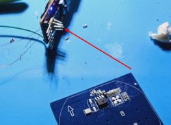
    Two circuit boards on a wooden surface, one is a small square module.

    went for super cheap basic

    Soldering station with a hot air gun on a carpet.
  • #60 21083513
    p.kaczmarek2
    Moderator Smart Home
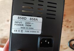
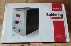
    I have tested similiar model but with different visuals:
    View of the power label on the 858D/858A model device. Packaging of Renew Force soldering station model 858D.
    I will be posting review soon, this or next month.
    Helpful post? Buy me a coffee.

Topic summary

The discussion focuses on the teardown and flashing process of Tuya generic WiFi wall light switches based on the BK7231N chip and T34 board, particularly 3-gang and 2-gang variants. The T34 chip is in a QFN package with no accessible programming pads, requiring desoldering for flashing with OpenBeken firmware. Users share detailed methods for desoldering and resoldering the T34 chip using hot air guns (temperatures around 350-480°C), flux, and soldering techniques, emphasizing the difficulty due to tiny pads and risk of PCB damage. Alternatives like needle probes for direct serial connection are discussed but often limited by concealed pads. Flashing is done via UART or SPI using FTDI232RL or CH340G-based USB-TTL adapters, with baud rates up to 921600. Some users report success without grounding the CEN pin by interrupting 3.3V supply to enter flash mode. Firmware extraction challenges include missing or manually created JSON configs. The devices often include additional components like BL0937 power measurement chips and WF480RA RF transceivers for remote control, sometimes unadvertised. Community members provide pin mappings for relays, buttons, and LEDs, and share templates for OpenBeken configuration. PowerSave mode and local NTP server support in OpenBeken are also mentioned. The discussion includes warnings about the complexity of flashing T34 devices, recommending caution and skill in SMD rework. Some users note differences in PCB versions, with older white-box versions having accessible TX/RX pads. Overall, the thread serves as a comprehensive resource for hardware hacking and firmware replacement on T34-based Tuya switches.
Summary generated by the language model.
ADVERTISEMENT