logo elektroda
logo elektroda
X
logo elektroda

[BK7231N / T34 ] Teardown Tuya Generic Wifi Wall Light Switch 3 Gang

CameronDev 21321 106
ADVERTISEMENT
📢 Listen (AI):
  • #91 21486400
    p.kaczmarek2
    Moderator Smart Home
    Well, I've posted it today :D btw, you have version without BL0937, so you really should use PowerSave. Add it to start script
    Helpful post? Buy me a coffee.
  • ADVERTISEMENT
  • #92 21486409
    kalikum
    Level 5  
    Great job

    I was just thinking about the powersave (i read about it from another of your post) and I have doubts about the functioning of some automation of my HA does it affect somehow to activate it?

    I'm going to try anyway ^.^
  • #93 21486413
    p.kaczmarek2
    Moderator Smart Home
    As far as I know, PowerSave only affects BL0937 devices and we actually even have a solution for that, which should be merged soon. There will be alternate PowerSave option/command for such cases. If your device is not using BL0937, you can enable PowerSave even now.

    Well, maybe also except IR devices, but I'm not sure. IR is using a high speed timer so it may not like MCU sleeping.

    You can also enable SSDP:


    Helpful post? Buy me a coffee.
  • #94 21486484
    kalikum
    Level 5  
    Powersave activate.

    The temperature drops quite compared to when it was working without powersave, I will confirm automatisms operation on HA

    Screenshot displaying diagnostic data of a device, including temperature, WiFi signal, and MQTT connection status.

    Thanks again for the information.
  • ADVERTISEMENT
  • #95 21486506
    p.kaczmarek2
    Moderator Smart Home
    Lower temperature is good, otherwise you may need to do this fix soon:
    https://www.elektroda.com/rtvforum/topic3898805.html
    Helpful post? Buy me a coffee.
  • #96 21487771
    kalikum
    Level 5  
    After a day with the porwersave, the temperature remains low but I cannot monitor it from the HA, it is not a problem, but is better if you know it in case someone uses it. Beyond this, automatisms work perfectly.

    I will still inform in the future, regards.
  • ADVERTISEMENT
  • #98 21619339
    jkwim
    Level 13  
    >>21135586

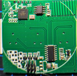
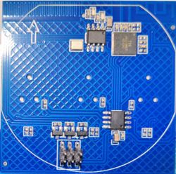
    I have a T34 based 3 Gang Switch which has the same PCB.

    T34 PCB with visible chips and programming header pins

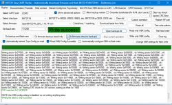
    I have obtained the backup successfully but the config file extraction fails.

    Then after many unsuccessful attempts, managed to flash.

    BK7231N Easy UART Flasher interface showing Write success! message

    Flash went successful but the unit does not come in to WiFi Access Point mode even after 5 power recycles.

    WiFi LED flashes once at low power on boot and then after a while goes into bright blue and stays lit.

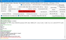
    Attempted to Read OBK Config but that also failed.

    What could be going wrong here?
    BK7231 Easy UART Flasher interface with “Only 0xFF bytes read!” error


    Here is the beginning part of the log:
    
    Preparing to write data file to chip - resetting bus and baud...
    Getting bus... (now, please do reboot by CEN or by power off/on)
    Getting bus success!
    Going to set baud rate setting (115200)!
    Will try to read device flash MID (for unprotect N):
    Flash MID loaded: 15701C
    Will now search for Flash def in out database...
    Flash def found! For: 15701C
    Flash information: mid: 15701C, icName: EN25QH16B, manufacturer: ESMT, szMem: 1000000, szSR: 1, cwUnp: 0, cwEnp: 7, cwMsk: 3C, sb: 2, lb: 4, cwdRd: 05-FF-FF-FF, cwdWr: 01-FF-FF-FF
    Entering SetProtectState(True)...
    sr: 40
    final sr: 40
    msk: 3c
    cw: 0, sb: 2, lb: 4
    bfd: 0
    SetProtectState(True) success!
    Going to do erase, start 69632, sec count 281!
    Erasing sector 69632... ok! Erasing sector 73728... ok! Erasing sector 77824... ok! Erasing sector 81920... ok! Erasing sector 86016... ok! Erasing sector 90112... ok! Erasing sector 94208... ok! Erasing sector 98304... ok!


    Log file of the backup (last part):
    
    Basic read operation finished, but now it's time to verify...
    Starting CRC check for 512 sectors, starting at offset 0x00
    CRC matches 0xD6EB617C!
    All read!
    Loaded total 0x200000 bytes 
    Wrote 2097152 to readResult_BK7231N_QIO_2025-28-7-17-02-36.bin
    Backup 2MB created, now will attempt to extract OBK config.
    It's not an OBK config, header is bad
    OBK config not found.
    Backup 2MB created, now will attempt to extract Tuya config.
    Tuya config extractor - magic is at 2023424 
    Saving debug Tuya decryption data to lastRawDecryptedStrings.bin
    Failed to extract Tuya keys - no json start found
    Sorry, failed to extract keys from Tuya Config in backup binary.
  • #100 21619518
    jkwim
    Level 13  
    >>21619354
    Thanks for that quick reply.
    Just to be sure I flashed a few more devices that I had with the same PCB and managed to successfully configure them.

    I reflashed the original unit using higher baud rate of 230400. Flashing becomes successful but it does not open up the WiFi AP. The WiFi LED get lit up after a while and then stays litup.

    I wonder whats wrong there.

    Other units which could be successfully flashed are of the same type.

    BTW the config file should be as follows:
    Note that I had to swap channels 1 & 3 from the original Tuya Config to get the proper button orientation on the GUI.

    The working config

    Device configuration, as extracted from Tuya: 
    - WiFi LED on P7
    - Button (channel 1) on P8
    - Relay (channel 3) on P9
    - Button (channel 2) on P14
    - Relay (channel 2) on P15
    - Button (channel 3) on P16
    - Relay (channel 1) on P17
    - Pair/Toggle All Button on P24
    Device seems to be using T34-3 module.
    And the Tuya section starts, as usual, at 2023424

    Added after 4 [hours]:

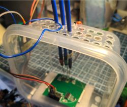
    Thought of sharing my new setup for flashing here as well so that others also can get some inspiration.

    Some time back I ordered these probles/needles from Aliexpress.
    https://www.aliexpress.com/item/1005007471008008.html

    Those are essentially some metal rods with pogo pins at one end and a female jumper wire headers at the other end.

    So I created a small setup like this:

    PCB under pogo pins mounted through holes in a plastic container lid

    I was hoping to get a nice stand made with acrylic sheets later but for the time being this works.

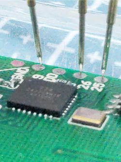
    The vertical probes rest on the solder pads/pins using their weight and the pogo needle points.

    Close-up of four pogo pins touching pads on a printed circuit board with a microcontroller.

    It takes some skill in accurately positioning the needle points of the pogo pins.

    For Power I used a 1.27mm female pin header to directly connect to the pin header on the PCB so that no soldering is required.

    I managed to flash a bunch of T34 devices quickly today using this setup (one device has some issue though).

    Added after 25 [minutes]:

    Hoping to recover the failed unit I tried flashing the backup file back into the device.

    I am getting the following error.

    All selected sectors erased!
    CheckRespond_FlashWrite4K: bad value returned?
    Writing sector 0x11000... Writing sector 69632 failed!
    Writing file data to chip failed.


    Does anybody know what this means?
  • ADVERTISEMENT
  • #102 21636218
    jkwim
    Level 13  
    roman0213 wrote:
    >>21619518 Hello, i have same board as you I'm not able to even read flash. how did you connect? just connect cen to ground, or did something else? I have separate 3,3v power supply I have tried also https://github.com/libretiny-eu/ltchiptool/releases did you tried?

    Thanks


    Actually the CEN trick did not work.

    What worked for me was to lift the TX Probe on and off the pad few times in my setup above and the communication got triggered.

    I still have not been able to recover the dead unit but others are ok.
  • #103 21637380
    roman0213
    Level 3  
    >>21636218 so you had setup like

    Probe connected to UART RX, UART TX, and CEN pins on a PCB.

    and you played with tx uart probe? I have 2 of these boards but no luck:( any idea?
  • #104 21638276
    jkwim
    Level 13  
    roman0213 wrote:
    >>21636218 so you had setup like

    Probe connected to UART RX, UART TX, and CEN pins on a PCB.

    and you played with tx uart probe? I have 2 of these boards but no luck:( any idea?


    Yes, it was not intentional but accidentally discovered that the make/break connection established the communication. To this date I haven't gone back to check what really happened as I had few units to be flashed and got them flashed in one go.
  • #105 21656671
    roman0213
    Level 3  
    jkwim wrote:
    roman0213 wrote:
    >>21636218 so you had setup like

    Probe connected to UART RX, UART TX, and CEN pins on a PCB.

    and you played with tx uart probe? I have 2 of these boards but no luck:( any idea?


    Yes, it was not intentional but accidentally discovered that the make/break connection established the communication. To this date I haven't gone back to check what really happened as I had few units to be flashed and got them flashed in one go.

    Finally, I have successfully flashed the device by interrupting the 3.3V pin. But are you using ESPHome and Home Assistant, or something else? I’m wondering how I can turn off the blue LED on the switch.
    Added after 3 [hours] 22 [minutes]:

    ok I found solution
    
    switch:
      - platform: gpio
        id: switch_1
        name: Relay 1
        pin: P17
      - platform: gpio
        id: switch_2
        name: Relay 2
        pin: P15
      - platform: gpio
        id: switch_3
        name: Relay 3
        pin: P9
      - platform: output
        name: "Status LED"
        output: status_led
    
    output:
      - platform: gpio
        pin: P7
        id: status_led
        inverted: true  
    
  • #106 21688587
    jkwim
    Level 13  
    roman0213 wrote:
    Finally, I have successfully flashed the device by interrupting the 3.3V pin. But are you using ESPHome and Home Assistant, or something else? I’m wondering how I can turn off the blue LED on the switch.


    Yes you could do the inversion but then you would loose the blue light on the buttons as well.

    That is what I am struggling with now. It appears that Tuya does some kind of PWM to make the WiFi LED go off but the switch LEDs will remain lit. The schematic that I was able to derive in earlier posts may have something to do with it. I haven't figured out yet.
  • #107 21689976
    jbolanosg
    Level 1  
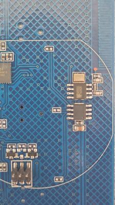
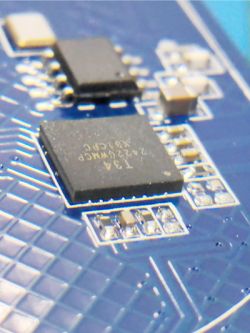
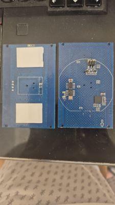
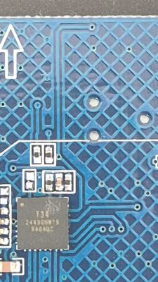
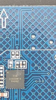
    >>21117203 I just bought 3 similar switches from the green box, but the board is a little different. I’m attaching images… Does anyone know if there’s a way to change the firmware without removing the chip? The chip is way too small to do it with needles… Would it be possible to find pins 25 and 26 on the traces and connect to them?
    Two blue PCB modules with electronic components and contact pads
    Close-up of a blue circuit board with microchip and conductive traces
    Close-up of a blue PCB with integrated circuit, SMD parts, and conductive traces
    Close-up of a blue PCB with ICs, soldered components, and circuitry traces
📢 Listen (AI):

Topic summary

The discussion focuses on the teardown and flashing process of Tuya generic WiFi wall light switches based on the BK7231N chip and T34 board, particularly 3-gang and 2-gang variants. The T34 chip is in a QFN package with no accessible programming pads, requiring desoldering for flashing with OpenBeken firmware. Users share detailed methods for desoldering and resoldering the T34 chip using hot air guns (temperatures around 350-480°C), flux, and soldering techniques, emphasizing the difficulty due to tiny pads and risk of PCB damage. Alternatives like needle probes for direct serial connection are discussed but often limited by concealed pads. Flashing is done via UART or SPI using FTDI232RL or CH340G-based USB-TTL adapters, with baud rates up to 921600. Some users report success without grounding the CEN pin by interrupting 3.3V supply to enter flash mode. Firmware extraction challenges include missing or manually created JSON configs. The devices often include additional components like BL0937 power measurement chips and WF480RA RF transceivers for remote control, sometimes unadvertised. Community members provide pin mappings for relays, buttons, and LEDs, and share templates for OpenBeken configuration. PowerSave mode and local NTP server support in OpenBeken are also mentioned. The discussion includes warnings about the complexity of flashing T34 devices, recommending caution and skill in SMD rework. Some users note differences in PCB versions, with older white-box versions having accessible TX/RX pads. Overall, the thread serves as a comprehensive resource for hardware hacking and firmware replacement on T34-based Tuya switches.
Summary generated by the language model.
ADVERTISEMENT