logo elektroda
logo elektroda
X
logo elektroda

Zemismart SPM01-D2TW Energy Counter: Data Issues with Tuya MCU and ESP02S Swap

Pete0815 3300 35
ADVERTISEMENT
  • #1 21071605
    Pete0815
    Level 7  
    Hi
    I´m very interested in using the Zemismart SPM01(https://www.zemismart.com/products/spm01-d2tw-zm) in the Wifi Version and therfore purchased one and found inside according webinfo a Tuya CB2S Chip.

    To get some information and closer to my personal wish of final result I also suddenly replaced the CB2S with ESP02S and analyzed the Data which are send from an Tuya MCU inside the smart meter.

    Now I`m struggeling because this data does not make really sence for me and in addition is only send by request (sendtuya0). Normally I would expect automatic provision of this data.

    At the moment I´m receiving 9 data points but only 3 contain data other than zero.
    Based on Tuya function I would expect voltage, power and current but only 1 of these three datapoints is changing. Tried to modify the load eg. 100W or 0W but also then only dpIx 6 is changing it´s value.

    19:32:48.334 TYA: Send "55aa0008000007"
    19:32:48.337 RSL: RESULT = {"TuyaSend":"Done"}
    19:32:48.418 DMP: 55 AA 03 07 00 08 01 02 00 04 00 00 00 00 18
    19:32:48.421 {"TuyaReceived":{"Data":"55AA03070008010200040000000018","Cmnd":7,"CmndData":"0102000400000000","DpType2Id1":0,"1":{"DpId":1,"DpIdType":2,"DpIdData":"00000000"}}}
    19:32:48.424 TYA: fnId=11 is set for dpId=1
    19:32:48.426 TYA: RX value 0 from dpId 1 
    19:32:48.429 DMP: 55 AA 03 07 00 08 02 02 00 04 00 00 00 00 19
    19:32:48.431 {"TuyaReceived":{"Data":"55AA03070008020200040000000019","Cmnd":7,"CmndData":"0202000400000000","DpType2Id2":0,"2":{"DpId":2,"DpIdType":2,"DpIdData":"00000000"}}}
    19:32:48.434 TYA: fnId=0 is set for dpId=2
    19:32:48.436 TYA: RX value 0 from dpId 2 
    19:32:48.438 DMP: 55 AA 03 07 00 0C 06 00 00 08 09 20 00 00 2D 00 00 04 7D
    19:32:48.441 {"TuyaReceived":{"Data":"55AA0307000C06000008092000002D0000047D","Cmnd":7,"CmndData":"06000008092000002D000004","DpType0Id6":"0x092000002D000004","6":{"DpId":6,"DpIdType":0,"DpIdData":"092000002D000004"}}}
    19:32:48.444 TYA: fnId=33 is set for dpId=6
    19:32:48.446 DMP: 55 AA 03 07 00 05 09 05 00 01 00 1D
    19:32:48.449 {"TuyaReceived":{"Data":"55AA0307000509050001001D","Cmnd":7,"CmndData":"0905000100","DpType5Id9":"0x00","9":{"DpId":9,"DpIdType":5,"DpIdData":"00"}}}
    19:32:48.451 TYA: fnId=0 is set for dpId=9
    19:32:48.453 DMP: 55 AA 03 07 00 05 0C 01 00 01 00 1C
    19:32:48.456 {"TuyaReceived":{"Data":"55AA030700050C010001001C","Cmnd":7,"CmndData":"0C01000100","DpType1Id12":0,"12":{"DpId":12,"DpIdType":1,"DpIdData":"00"}}}
    19:32:48.459 TYA: fnId=0 is set for dpId=12
    19:32:48.460 DMP: 55 AA 03 07 00 08 0D 02 00 04 00 00 00 00 24
    19:32:48.463 {"TuyaReceived":{"Data":"55AA030700080D0200040000000024","Cmnd":7,"CmndData":"0D02000400000000","DpType2Id13":0,"13":{"DpId":13,"DpIdType":2,"DpIdData":"00000000"}}}
    19:32:48.466 TYA: fnId=0 is set for dpId=13
    19:32:48.468 TYA: RX value 0 from dpId 13 
    19:32:48.470 DMP: 55 AA 03 07 00 0C 11 00 00 08 07 01 00 0D 08 00 00 00 4B
    19:32:48.473 {"TuyaReceived":{"Data":"55AA0307000C110000080701000D080000004B","Cmnd":7,"CmndData":"110000080701000D08000000","DpType0Id17":"0x0701000D08000000","17":{"DpId":17,"DpIdType":0,"DpIdData":"0701000D08000000"}}}
    19:32:48.476 TYA: fnId=32 is set for dpId=17
    19:32:48.485 DMP: 55 AA 03 07 00 1C 12 00 00 18 01 01 00 3C 03 01 00 FD 04 00 00 B4 07 01 00 00 08 00 00 1E 09 00 00 00 7D
    19:32:48.488 {"TuyaReceived":{"Data":"55AA0307001C120000180101003C030100FD040000B4070100000800001E090000007D","Cmnd":7,"CmndData":"120000180101003C030100FD040000B4070100000800001E09000000","DpType0Id18":"0x0101003C030100FD040000B4070100000800001E09000000","18":{"DpId":18,"DpIdType":0 "DpIdData":"0101003C030100FD040000B4070100000800001E09000000"}}}
    19:32:48.492 TYA: fnId=0 is set for dpId=18
    19:32:48.495 DMP: 55 AA 03 2D 00 00 2F


    My question now is, is it possible to gain additional knowledge from the desoldered CB2S with your tools? Connecting this CB2S by USB-TTL converter to read it out. Is this sth you would recommend?

    Second question in case it´s better to back one step and resolder the CB2S according your guideline https://www.elektroda.com/rtvforum/topic3970199.html it says 2 steps. First step without 5V connected without Wifi but in case of CB2S there ist no 5V only 3,3V at the Chip. So how to do these 2 seperate steps ?
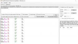
    Screenshot of TuyaMCU Explorer/Analyzer showing packet data in hexadecimal format.


    Thanks?
  • ADVERTISEMENT
  • #2 21072162
    p.kaczmarek2
    Moderator Smart Home
    The best and more precise answer is most likely our TuyaMCU guide, here:
    TuyaMCU flashing, setup and configuration guide - configure dpIDs for Home Assistant


    Pete0815 wrote:

    To get some information and closer to my personal wish of final result I also suddenly replaced the CB2S with ESP02S and analyzed the Data which are send from an Tuya MCU inside the smart meter.

    I would rather analyze it with original firmware, here is one option to do that:
    TuyaMCU analyzer - UART packet decoder for Tuya devices - dpID detector

    Pete0815 wrote:

    Now I`m struggeling because this data does not make really sence for me and in addition is only send by request (sendtuya0). Normally I would expect automatic provision of this data.

    This happens sometimes with OBK as well, it may be by TuyaMCU design. In OBK we solve it with:
    
    // every 10 seconds, request update from TuyaMCU
    addRepeatingEvent 10 -1 tuyaMcu_sendQueryState
    

    See more: https://www.elektroda.com/rtvforum/find.php?q=tuyaMcu_sendQueryState


    Pete0815 wrote:

    At the moment I´m receiving 9 data points but only 3 contain data other than zero.

    I don't remember Tasmota details, but for best result I recommed simulating 0x04 wifi state for the MCU. In OBK we do:
    
    tuyaMcu_defWiFiState 4
    

    Some of devices do not publish their states fully unless they think they are connected to the cloud. Some other devices even may beep or blink when not paired.


    Pete0815 wrote:

    My question now is, is it possible to gain additional knowledge from the desoldered CB2S with your tools?

    You can for example consider also Tuya API method: Extracting DpIDs for TUYA MCU devices
    You can also share 2MB backup of your device as long as you haven't paired it yet with your WiFi.

    Futhermore, once on OpenBeken, I could help a little more. My Tasmota knowledge regarding TuyaMCU is a bit rusty. Btw, OpenBeken emulates Tasmota JSON, so you can consider trying that out.

    Pete0815 wrote:

    Connecting this CB2S by USB-TTL converter to read it out. Is this sth you would recommend?

    Putting back CB2S into the original device and capturing communication between CB2S and MCU in a safe manner (do not power device from mains, only from USB) can help.

    Pete0815 wrote:

    Second question in case it´s better to back one step and resolder the CB2S according your guideline https://www.elektroda.com/rtvforum/topic3970199.html it says 2 steps. First step without 5V connected without Wifi but in case of CB2S there ist no 5V only 3,3V at the Chip. So how to do these 2 seperate steps ?
    Screenshot of TuyaMCU Explorer/Analyzer showing packet data in hexadecimal format.


    I apologize for the confusion. This particular guide you are referencing assumes that you power it from 5V by inserting 5V before the AMS1117-3.3V LDO on the board. So, with 5V at the input of AMS1117-3.3V LDO you will get also 3.3V at the output (for WiFi module). This is useful because it ensures that most of the board is powered without powering it from mains, because powering such device from mains would be VERY DANGEROUS, that's why we are using a single 5V source from USB.
    The particular step 2 you are referencing recommends powering it off before capture because we want to capture all communication from the start, from the early boot time, so we first start capture, and then apply the 5V power.

    If there is no AMS1117-3.3V on your board, there may be a step down converter instead. Step down converter will have the same function, it will also be converting either 5V or 12V (depending on your device) to 3.3V for WiFi module. In this case you can connect 5V to the input of such step down converter.

    Be aware that the capture method may vary between devices and may require some basic understanding of how your device works. The main rule of TuyaMCU capture is to never power your device from mains while having UART connected.
    If you really want to power it from mains, then you should use isolation module, but that's a different story...

    You can also share some photos of your device, this may help me guide you futher.
    Helpful post? Buy me a coffee.
  • ADVERTISEMENT
  • #3 21072182
    Pete0815
    Level 7  

    p.kaczmarek2 wrote:

    You can also share some photos of your device, this may help me guide you further.


    Thank you very much. I will need some time to understand your reply and read all the great information.

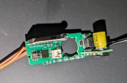
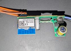
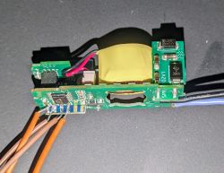
    So let's reply to a simple one and please have a look at the photos and don't be worried. I'll never connect mains while doing these kinds of stuff!

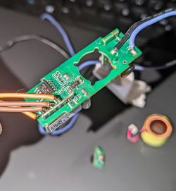
    2 photos I dismounted the coil and the board with the push button to have a better view.

    View of a disassembled circuit board with electronic components. Dismantled circuit board with electronic components and a module labeled Model: CBZS. The image shows a disassembled electronic component with a coil and button board on a gray background.
  • #4 21072199
    p.kaczmarek2
    Moderator Smart Home
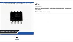
    I've looked at your photos and I can see LP2178 chip, which is most likely an non-isolated step down converter for mains voltage to 5V DC conversion:
    Image of LP2178 chip on product page.
    We still need to figure out where 5V is converted to 3.3V on your board.
    Helpful post? Buy me a coffee.
  • #5 21072224
    Pete0815
    Level 7  
    p.kaczmarek2 wrote:
    We still need to figure out where 5V is converted to 3.3V on your board.


    Guess this MicrOne LDO SBWF is what we are looking for
    Printed circuit board with electronic components and soldered wires.

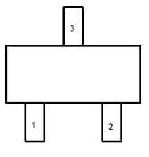
    In this SOT23-3 Version it should be
    Pin1: Vout = 3,3V
    Pin2: Vss = GND
    Pin3: Vin= 5V

    Pinout diagram of a SOT23-3 integrated circuit.
  • #6 21072602
    p.kaczmarek2
    Moderator Smart Home
    Really? I would not expect that. Please at least verify with the multimether whether the pins are indeed connected to ground, 5V input and the 3.3V pad of WiFi module.
    Helpful post? Buy me a coffee.
  • #7 21072614
    Pete0815
    Level 7  

    Checked and confirmed connection to 3.3V and GND Pin of the CB2S module

    Why are you surprised? I had similar LDO at my ESP32-S2 Mini Modules from MicrOne.
  • #8 21072618
    p.kaczmarek2
    Moderator Smart Home
    So CB2S with original firmware is back in?

    Well, now you do what I said earlier... 5V to the input of the LDO (so you get 3.3V at the output), and try to capture communication....

    Of course, you also have to do it in an organised manner, maybe do separate capture session for each activity in Tuya application, etc.... that's how I do it, anyway.

    And I am assuming here that your device will still work correctly while being powered from 5V. If not, then things will get more complicated, you will have to consider doing a capture with isolated UART...

    Added after 1 [minutes]:

    Pete0815 wrote:
    Why are you surprised? I Had similar LDO at my ESP32-S2 Mini Modules from MicrOne.

    I have opened many, many Tuya devices, as you can see here: https://openbekeniot.github.io/webapp/devicesList.html and almost every of those devices either had a larger LDO, namely AMS1117-3.3V or a step down converter (chip with 6 legs or so and with inductor nearby). I didn't see much devices like your one.
    Helpful post? Buy me a coffee.
  • #9 21072681
    Pete0815
    Level 7  

    p.kaczmarek2 wrote:

    And I am assuming here that your device will still work correctly while being powered from 5V. If not, then things will get more complicated, you will have to consider doing a capture with isolated UART...


    Thx. Mmmh seems not to be at the moment. Cannot see the device in the Tuya App and also my Wifi access point does not recognize it.

    capturing while connecting 5V gives endless loop of
    55AA032B00002D

    Same as shown above.

    Maybe the USB TTL has not enough power to power the whole device.
  • ADVERTISEMENT
  • Helpful post
    #10 21072736
    divadiow
    Level 34  
    I wonder if this user got any further. device looks similar https://www.elektroda.com/rtvforum/topic4007182.html

    Added after 44 [minutes]:

    p.kaczmarek2 wrote:
    You can also share 2MB backup of your device as long as you haven't paired it yet with your WiFi


    or if you have, delete and wipe from the app if still present, to clear your wifi details.

    or if already flashed with OBK, extract the tuya config and post the small file

    Google homepage in a web browser with dark theme highlighting UK location.
  • #11 21074114
    Pete0815
    Level 7  
    divadiow wrote:
    I wonder if this user got any further. device looks similar https://www.elektroda.com/rtvforum/topic4007182.html

    Added after 44 [minutes]:

    p.kaczmarek2 wrote:
    You can also share 2MB backup of your device as long as you haven't paired it yet with your WiFi


    or if you have, delete and wipe from the app if still present, to clear your wifi details.


    Thanks and this device seems to be same type.

    Because at the moment I´m not getting any further and also waiting for a new USB TTL converter with AMS1117 which should have enough power.

    Can you say what sw tool to use for this 2MB backup? Is it the OpenBK flash tool? aand I can make use of this function?
    Screenshot of the BK7231 Easy UART Flasher tool

    And for the Tasmota testing and with some help via manual request command ("tuyasend0") one datapoint (dpIx 6) received in raw format could be identified:
    BIN data table with headers and values, showing details like Header, State, dpIx, and values related to voltage, current, and active power.

    so it contains voltage, current and active power

    But as mentioned this is only by manual request command and the LED is still blinking and there are several unidentified dpIx without changes (counter values kwh; maybe?) or values at all.

    Edit: Just did it and received:
    {
    	"baud":"9600}e",
    	"ap_passwd":"null",
    	"country_code":"null",
    	"bt_mac":"null",
    	"bt_hid":"null",
    	"prod_test":"false",
    	"fac_pin":"brnwqs0ifofy3rzugiAgw_di{abi",
    	"id":"null",
    	"swv":"2.1.6",
    	"bv":"40.00",
    	"pv":"2.2",
    	"lpv":"3.4",
    	"pk":"brnwqs0ifofy3rzu",
    	"firmk":"key83r5jq9qqeaxt",
    	"cadv":"1.0.5",
    	"cdv":"1.0.0",
    	"dev_swv":"3.0.2",
    	"s_id":"null",
    	"dtp":"9",
    	"sync":"0",
    	"attr_num":"1",
    	"mst_tp_0":"9",
    	"mst_ver_0":"3.0.2",
    	"mst_tp_1":"0",
    	"mst_ver_1":"null",
    	"mst_tp_2":"0",
    	"mst_ver_2":"null",
    	"mst_tp_3":"0",
    	"mst_ver_3":"null } ",
    	"*Agw_wsm{nc_tp":"0",
    	"ssid":"null",
    	"passwd":"null",
    	"md":"0",
    	"random":"0",
    	"wfb64":"1",
    	"stat":"0",
    	"token":"null",
    	"region":"null",
    	"reg_key":"null",
    	"dns_prio":"0 }4& Awf_start_mdy",
    	"auth_key":"oXcG4D46h1Ehc59FFfLKAu9LMxHHEnIZ",
    	"ap_s4d":"SmartLife",
    	"psk_key":"FB1gzDvpIMz9kjvWDivQ5MUNHTiITXuIxorIl",
    	"ap_ssid":"SmartLife",
    	"lckey":"null",
    	"h_url":"null",
    	"h_ip":"null",
    	"hs_url":"null",
    	"hs_ip":"null",
    	"hs_psk":"null",
    	"hs_psk_ip":"null",
    	"mqs_url":"null",
    	"mqs_ip":"null",
    	"mq_url":"null",
    	"mq_ip":"null",
    	"ai_sp":"null",
    	"ai_sp_ip":"null",
    	"mq_psk":"null",
    	"mq_psk_ip":"null",
    	"lp_url":"null",
    	"lp_ip":"null",
    	"time_z":"null",
    	"s_time_z":"null",
    	"wx_app_id":"null",
    	"wx_uuid":"null",
    	"dy_tls_m":"0",
    	"cloud_cap":"0",
    	"psk21_key":"null } 0Atls_ca_cnt00Ais_stride0{abi",
    	"mode":"ro",
    	"property":"{min",
    	"max":"99999999",
    	"scale":"2",
    	"step":"1",
    	"type":"value}",
    	"{type":"obj",
    	"{mode":"ro",
    	"maxlen":"17}",
    	"cnt":"0}A000003595c[{type"
    }


    Please also see backup attached. Can you please advice what could be done? Thx!
  • #12 21074304
    divadiow
    Level 34  
    I'm not very good at setting up needed autoexec config yet but here are the dpIDs for that firmware to get you started

    Code: Text
    Log in, to see the code


    not sure if that's just the TuyaMCU dpIDs and the ones missing from that, but are in the below, are software/app functions? eg dpID 1

    Code: Text
    Log in, to see the code
  • #13 21074388
    Pete0815
    Level 7  

    Thank you very much. This is looking very good and gives me information not known so far.

    The second code/mapping table looks slightly familiar because of data topics I have seen in the Tuya App for this type of device.

    The backup I've uploaded was from the desoldered CB2S chip because I was not able to read out a soldered CB2S in the circuit.
  • ADVERTISEMENT
  • #14 21077845
    p.kaczmarek2
    Moderator Smart Home
    Later you can create custom panel for OBK for your device:
    Alternative control html page for TOMPD-63-WIFI
    Helpful post? Buy me a coffee.
  • #15 21080512
    Pete0815
    Level 7  

    Thanks. Guess I have a very rough understanding but at the moment I'm not really getting anywhere

    So at the moment my guess is, is best to go with openbk and learn as much as possible. Because openbk is totally new for me please confirm next steps?

    I've made a backup of the CB2S and therefore now I can flash this desoldered chip with openbk, right?

    After soldering it again into circuit I should learn how to configure openbk with the information @divadiow gave to me. This was also explained by creating an autoexec.bat

    similar as explained here:
    https://www.youtube.com/watch?v=kXi8S12tmC8

    I have to learn how to do that...

    Is this understanding right?
  • #16 21080800
    p.kaczmarek2
    Moderator Smart Home
    Flash OpenBeken to your chip, solder it back, connect to AP, set your WiFi SSID and pass, make sure it connects to your WiFi...

    Then here is TuyaMCU guide:
    TuyaMCU flashing, setup and configuration guide - configure dpIDs for Home Assistant
    But we can also guide you here, step by setp.
    Helpful post? Buy me a coffee.
  • #17 21080872
    Pete0815
    Level 7  
    Thanks. OpenBeken is flashed and chip is already soldered back and working in my wifi.

    According the info from the other contribution there is no need to configure the GPIOs Pins (P10 P11) to work with the Tuya MCU BL0942, right?

    Then I generated in the file system an autoexec.bat with the following content:

    // Start TuyaMCu driver
    startDriver TuyaMCU
    // set TuyaMCU baud rate
    //tuyaMcu_setBaudRate 115200
    // set TuyaMCU default wifi state 0x04, which means "paired",
    // because some TuyaMCU MCUs will not report all data
    // unless they think they are connected to cloud
    tuyaMcu_defWiFiState 4


    Mqtt is connected
    In the Log I can identify 3 dpIx (1,2,6) coming from the MCU.

    Info:TuyaMCU:TuyaMCU_ParseStateMessage: raw data 4 int: 0
    Info:TuyaMCU:TUYAMCU received: 55 AA 03 07 00 0C 06 00 00 08 09 20 00 00 32 00 00 04 82 
    Info:TuyaMCU:TuyaMCU_ProcessIncoming[ver=3]: processing command 7 (State) with 19 bytes
    Info:TuyaMCU:TuyaMCU_ParseStateMessage: processing dpId 6, dataType 0-DP_TYPE_RAW and 8 data bytes
    Info:TuyaMCU:TUYAMCU received: 55 AA 03 2B 00 00 2D 
    Info:TuyaMCU:TuyaMCU_ProcessIncoming[ver=3]: processing command 43 (NetworkStatus) with 7 bytes
    Info:TuyaMCU:TuyaMCU_ProcessIncoming: (test for S09 calendar/IR device) received TUYA_CMD_NETWORK_STATUS 0x2B 
    Info:TuyaMCU:TUYAMCU received: 55 AA 03 00 00 01 01 04 
    Info:TuyaMCU:TuyaMCU_ProcessIncoming[ver=3]: processing command 0 (Hearbeat) with 8 bytes
    Info:TuyaMCU:TUYAMCU received: 55 AA 03 07 00 08 01 02 00 04 00 00 00 00 18 
    Info:TuyaMCU:TuyaMCU_ProcessIncoming[ver=3]: processing command 7 (State) with 15 bytes
    Info:TuyaMCU:TuyaMCU_ParseStateMessage: processing dpId 1, dataType 2-DP_TYPE_VALUE and 4 data bytes
    Info:TuyaMCU:TuyaMCU_ParseStateMessage: raw data 4 int: 0
    Info:TuyaMCU:TUYAMCU received: 55 AA 03 07 00 08 02 02 00 04 00 00 00 00 19 
    Info:TuyaMCU:TuyaMCU_ProcessIncoming[ver=3]: processing command 7 (State) with 15 bytes
    Info:TuyaMCU:TuyaMCU_ParseStateMessage: processing dpId 2, dataType 2-DP_TYPE_VALUE and 4 data bytes
    Info:TuyaMCU:TuyaMCU_ParseStateMessage: raw data 4 int: 0
    Info:TuyaMCU:TUYAMCU received: 55 AA 03 07 00 0C 06 00 00 08 09 1A 00 00 31 00 00 04 7B 
    Info:TuyaMCU:TuyaMCU_ProcessIncoming[ver=3]: processing command 7 (State) with 19 bytes
    Info:TuyaMCU:TuyaMCU_ParseStateMessage: processing dpId 6, dataType 0-DP_TYPE_RAW and 8 data bytes
    Info:TuyaMCU:TUYAMCU received: 55 AA 03 2B 00 00 2D 
    Info:TuyaMCU:TuyaMCU_ProcessIncoming[ver=3]: processing command 43 (NetworkStatus) with 7 bytes
    Info:TuyaMCU:TuyaMCU_ProcessIncoming: (test for S09 calendar/IR device) received TUYA_CMD_NETWORK_STATUS 0x2B 
    Info:TuyaMCU:TUYAMCU received: 55 AA 03 00 00 01 01 04 
    Info:TuyaMCU:TuyaMCU_ProcessIncoming[ver=3]: processing command 0 (Hearbeat) with 8 bytes
    Info:TuyaMCU:TUYAMCU received: 55 AA 03 07 00 08 01 02 00 04 00 00 00 00 18 
    Info:TuyaMCU:TuyaMCU_ProcessIncoming[ver=3]: processing command 7 (State) with 15 bytes
    Info:TuyaMCU:TuyaMCU_ParseStateMessage: processing dpId 1, dataType 2-DP_TYPE_VALUE and 4 data bytes
    Info:TuyaMCU:TuyaMCU_ParseStateMessage: raw data 4 int: 0
    Info:TuyaMCU:TUYAMCU received: 55 AA 03 07 00 08 02 02 00 04 00 00 00 00 19 
    Info:TuyaMCU:TuyaMCU_ProcessIncoming[ver=3]: processing command 7 (State) with 15 bytes
    Info:TuyaMCU:TuyaMCU_ParseStateMessage: processing dpId 2, dataType 2-DP_TYPE_VALUE and 4 data bytes
    Info:TuyaMCU:TuyaMCU_ParseStateMessage: raw data 4 int: 0
    Info:TuyaMCU:TUYAMCU received: 55 AA 03 07 00 0C 06 00 00 08 09 1D 00 00 31 00 00 04 7E 
    Info:TuyaMCU:TuyaMCU_ProcessIncoming[ver=3]: processing command 7 (State) with 19 bytes
    Info:TuyaMCU:TuyaMCU_ParseStateMessage: processing dpId 6, dataType 0-DP_TYPE_RAW and 8 data bytes
    Info:TuyaMCU:TUYAMCU received: 55 AA 03 00 00 01 01 04 
    Info:TuyaMCU:TuyaMCU_ProcessIncoming[ver=3]: processing command 0 (Hearbeat) with 8 bytes
    Info:TuyaMCU:TUYAMCU received: 55 AA 03 2B 00 00 2D 
    Info:TuyaMCU:TuyaMCU_ProcessIncoming[ver=3]: processing command 43 (NetworkStatus) with 7 bytes
    Info:TuyaMCU:TuyaMCU_ProcessIncoming: (test for S09 calendar/IR device) received TUYA_CMD_NETWORK_STATUS 0x2B 
    Info:TuyaMCU:TUYAMCU received: 55 AA 03 07 00 08 01 02 00 04 00 00 00 00 18 
    Info:TuyaMCU:TuyaMCU_ProcessIncoming[ver=3]: processing command 7 (State) with 15 bytes
    Info:TuyaMCU:TuyaMCU_ParseStateMessage: processing dpId 1, dataType 2-DP_TYPE_VALUE and 4 data bytes
    Info:TuyaMCU:TuyaMCU_ParseStateMessage: raw data 4 int: 0
    Info:TuyaMCU:TUYAMCU received: 55 AA 03 07 00 08 02 02 00 04 00 00 00 00 19 
    Info:TuyaMCU:TuyaMCU_ProcessIncoming[ver=3]: processing command 7 (State) with 15 bytes
    Info:TuyaMCU:TuyaMCU_ParseStateMessage: processing dpId 2, dataType 2-DP_TYPE_VALUE and 4 data bytes
    Info:TuyaMCU:TuyaMCU_ParseStateMessage: raw data 4 int: 0
    Info:TuyaMCU:TUYAMCU received: 55 AA 03 07 00 0C 06 00 00 08 09 1D 00 00 32 00 00 04 7F 
    Info:TuyaMCU:TuyaMCU_ProcessIncoming[ver=3]: processing command 7 (State) with 19 bytes
    Info:TuyaMCU:TuyaMCU_ParseStateMessage: processing dpId 6, dataType 0-DP_TYPE_RAW and 8 data bytes
    Info:TuyaMCU:TUYAMCU received: 55 AA 03 00 00 01 01 04 
    Info:TuyaMCU:TuyaMCU_ProcessIncoming[ver=3]: processing command 0 (Hearbeat) with 8 bytes
    Info:TuyaMCU:TUYAMCU received: 55 AA 03 2B 00 00 2D 
    Info:TuyaMCU:TuyaMCU_ProcessIncoming[ver=3]: processing command 43 (NetworkStatus) with 7 bytes
    Info:TuyaMCU:TuyaMCU_ProcessIncoming: (test for S09 calendar/IR device) received TUYA_CMD_NETWORK_STATUS 0x2B 
    Info:TuyaMCU:TUYAMCU received: 55 AA 03 00 00 01 01 04 
    Info:TuyaMCU:TuyaMCU_ProcessIncoming[ver=3]: processing command 0 (Hearbeat) with 8 bytes


    Is this sufficiant to go on withe the dpIx allocation?
  • #18 21080877
    p.kaczmarek2
    Moderator Smart Home
    Yes, you can also try to run:
    
    tuyaMcu_sendQueryState
    

    to request all data points.

    Then, continue writing your autoexec.bat, you can use that "reset svm and run" button most of the time instead of doing full reboot and you should be still able to see results on the main html page
    Helpful post? Buy me a coffee.
  • #19 21082232
    Pete0815
    Level 7  
    Thanks.
    By sending the cmd
    tuyaMcu_sendQueryState


    I receive all the known and shown above dpIx

    Based on the examples for TuyaMCU Link I got a big step further

    My autoexec.bat looks like this:

    
    // Clear all previous definitions
    clearIO
    
    // clear flags
    // flags 0
    
    // set flag 46
    SetFlag 46 1
    
    // start TuyaMCU driver
    startDriver TuyaMCU
    tuyaMcu_setBaudRate 9600
    
    // This one is better than tuyaMcu_defWiFiState 4;  MQTTState 1 = WiFiState 4
    // issuing of tuyaMcu_defWiFiState 4 continues the script,
    // but doesnt report to MQTT since there is still no connection.
    // if you didn't setup MQTT connection then issue tuyaMcu_defWiFiState 4
    // and comment waitFor MQTTState 1
    
    waitFor MQTTState 1
    // tuyaMcu_defWiFiState 4
    
    // Total energy - Dpid 1 "total_forward_energy" -> channel 4
    linkTuyaMCUOutputToChannel 1 val 4
    setChannelType 4 EnergyTotal_kWh_div100
    setChannelLabel 4 "Total Energy"
    
    // Measurements - Dpid 6 "phase_a" - channel RAW_TAC2121C_VCP -> 5,6,7
    // TAC2121C VoltageCurrentPower Packet
    // This will automatically set voltage, power and current
    linkTuyaMCUOutputToChannel 6 RAW_TAC2121C_VCP
    setChannelType 5 Voltage_div10
    setChannelLabel 5 "Voltage"
    setChannelType 6 Power
    setChannelLabel 6 "Power"
    setChannelType 7 Current_div1000
    setChannelLabel 7 "Current"
    
    
    // Fault - Dpid 9 "fault" -> channel 9
    linkTuyaMCUOutputToChannel 9 raw 9
    setChannelType 9 ReadOnly
    setChannelLabel 9 "Fault"
    
    // Prepayment on-off - Dpid 11 "switch_prepayment" -> channel 2
    linkTuyaMCUOutputToChannel 11 bool 2
    setChannelType 2 toggle
    setChannelLabel 2 "Prepayment"
    
    // Clear Energy Counters - Dpid 12 "clear_energy" -> channel 3
    linkTuyaMCUOutputToChannel 12 bool 3
    setChannelType 3 toggle
    setChannelLabel 3 "Clear Energy Counters"
    
    // Prepaid energy - Dpid 13 "balance_energy" -> channel 11
    linkTuyaMCUOutputToChannel 13 val 11
    setChannelType 11 EnergyTotal_kWh_div100
    setChannelLabel 11 "Total Prepaid Energy"
    
    // Charge Prepayment - Dpid 14 "charge_energy" - channel 12
    linkTuyaMCUOutputToChannel 14 val 12
    setChannelType 12 TextField
    setChannelLabel 12 "Purchased Energy [kWh*100], i.e. 1kWh = 100"
    
    // Settings 1 - Dpid 17 "alarm_set_1" - channel 13
    linkTuyaMCUOutputToChannel 17 val 13
    setChannelType 13 TextField
    setChannelLabel 13 "Leakage Current Protection Settings"
    
    // Settings 2 - Dpid 18 "alarm_set_2" -> channel 10
    linkTuyaMCUOutputToChannel 18 raw 10
    setChannelType 10 ReadOnly
    setChannelLabel 10 "UV, OV, Max. Current Protections Settings"
    
    // Breaker Id - Dpid 19 "breaker_id" -> channel 0
    linkTuyaMCUOutputToChannel 19 str 0
    setChannelType 0 ReadOnly
    setChannelLabel 0 "Breaker ID"
    
    // The above are read only channels. Except Settings 2 (mapped on channel 10), but since we cannot set it due to wrong parse of TuyaMCU driver - for now read only
    
    
    // NOTE: addRepeatingEvent [RepeatTime] [RepeatCount]
    // code below will forever Send query state command every 5 seconds
    // addRepeatingEvent 5 -1 tuyaMcu_sendQueryState 
    
    // AngelOfDeath - We don't need it forever, since TuyaMCU sends everything when necessary
    // we need it just first time to obtain initial status. Some dpIDs not reported without asking
    tuyaMcu_sendQueryState


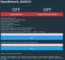
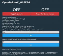
    And my OpenBeken Webpage looks like this:

    Screenshot of the OpenBekenX interface with energy management settings.

    What I´m not able to configure is because of missing examples: dpIx 2

    DP 2, VALUE(ro), cur_neutral


    dpIx 6 is working but next step I´m struggeling is the energy count (Dpid 1). Nothing seen beside 0kWh so far.

    @divadiow mentioned an app functionality for eg dpIx 1 which is this energy counter and I have configured in the autoexec.bat:
    // Total energy - Dpid 1 "total_forward_energy" -> channel 4
    linkTuyaMCUOutputToChannel 1 val 4
    setChannelType 4 EnergyTotal_kWh_div100
    setChannelLabel 4 "Total Energy"


    But no values so far:

    Info:TuyaMCU:TUYAMCU received: 55 AA 03 07 00 08 01 02 00 04 00 00 00 00 18 
    Info:TuyaMCU:TuyaMCU_ProcessIncoming[ver=3]: processing command 7 (State) with 15 bytes
    Info:TuyaMCU:TuyaMCU_ParseStateMessage: processing dpId 1, dataType 2-DP_TYPE_VALUE and 4 data bytes
    Info:TuyaMCU:TuyaMCU_ParseStateMessage: raw data 4 int: 0


    Kindly ask for your experienced hints what is missing/to do to activate?

    Thanks!
  • #20 21098701
    vincenzoernst1
    Level 6  

    looks good so far. this looks almost done. how is current state?
  • #21 21098718
    Pete0815
    Level 7  

    No progress from my side.

    dpIx 6 working but nothing more and couldn't find any hint how other dpIx has to be activated or used.

    OpenBeken Webpage looks nice but no functionality beside dpIx 6.
  • #22 21098747
    p.kaczmarek2
    Moderator Smart Home
    This may help: https://www.elektroda.com/rtvforum/topic3959907.html#20460951
    According to this user, the uartSendHex 55AA000300010407 also can help, when done manually.
    Helpful post? Buy me a coffee.
  • #23 21098802
    Pete0815
    Level 7  

    p.kaczmarek2 wrote:
    the uartSendHex 55AA000300010407 also can help, when done manually.


    Thanks. I´m not sure about it. I receive
    Info:TuyaMCU:TuyaMCU_ParseStateMessage: processing dpId 1, dataType 2-DP_TYPE_VALUE and 4 data bytes
    Info:TuyaMCU:TuyaMCU_ParseStateMessage: raw data 4 int: 1
    Info:TuyaMCU:TUYAMCU received: 55 AA 03 07 00 08 02 02 00 04 00 00 00 00 19 


    So an Integer 1 and before I only have seen Integer 0 but at the openBeken webpage where its configured to channel 4 which is EnergyTotal_kwh_div100 is still 0. so have to check with bigger load.

    Edit:

    No even with a bigger load 2kW no changes at dpIx 1:

    Info:TuyaMCU:TuyaMCU_ProcessIncoming[ver=3]: processing command 7 (State) with 15 bytes
    Info:TuyaMCU:TuyaMCU_ParseStateMessage: processing dpId 1, dataType 2-DP_TYPE_VALUE and 4 data bytes
    Info:TuyaMCU:TuyaMCU_ParseStateMessage: raw data 4 int: 1
    Info:GEN:No change in channel 4 (still set to 1) - ignoring

  • #25 21098960
    Pete0815
    Level 7  

    p.kaczmarek2 wrote:
    Are you forcing WiFi state 0x04?


    Not until now because of
    waitFor MQTTState 1


    Now I changed to test but seems to be same.

    Good news: The dpId 1 has changed now.

    I tested with 800W load for 1.5 minutes which are 0.02kWh

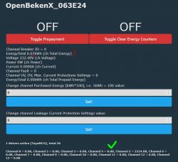
    Channel 4 changed from 6 to 8 which is great but within the Webview the counter says 0.07kWh ????

    Screenshot of OpenBekenX_063E24 control panel with energy settings.

    Nevertheless the situation is improving. Big Thanks!
  • #26 21099001
    p.kaczmarek2
    Moderator Smart Home
    I can see your autoexec.bat fragment:
    
    
    // NOTE: addRepeatingEvent [RepeatTime] [RepeatCount]
    // code below will forever Send query state command every 5 seconds
    // addRepeatingEvent 5 -1 tuyaMcu_sendQueryState 
    
    // AngelOfDeath - We don't need it forever, since TuyaMCU sends everything when necessary
    // we need it just first time to obtain initial status. Some dpIDs not reported without asking
    tuyaMcu_sendQueryState
    

    I would say that some devices may need that in repeating event because some TuyaMCU devices are not sending data often if we don't ask. So maybe you can still give it a go. OR run this command from console and see if anything changes.
    Helpful post? Buy me a coffee.
  • #27 21099398
    Pete0815
    Level 7  

    Thanks and tried by manual command and now activated the repeating command (every 5 sec) in the autoexec.bat but so far without identifiable change in result.

    My impression is that dpIx 1 is reported after first command execution but I was wondering about the difference in value presentation.
    As you can see by the log the integer value was 8 and channel 4 is also reported with value 8 but the presentation in the overview says 0,07kWh . This I´m struggling to understand because there seems to be not smaller number to have e.g a rounding error/problem.


    This morning i booted the device to test the manual & repeating query but now it gets even more strange because of different/lower values than yesterday evening.

    Today dpIx 1 value is 5 (channel 4 also) and the webview says again 0,04kWh.

    So why this reduction overnight without having powered up the device? And again this mismatch between log/channel value and the Energy counter presentation at the web page? Should I just ignore this? Because just checked the published Mqtt value and this is 5.
  • #28 21099429
    vincenzoernst1
    Level 6  

    hmm. this units have a 2 way measurement. so you maybe changed current flow?!
  • #29 21099598
    Pete0815
    Level 7  

    User interface of the OpenBekenX application showing switches and energy values.

    After some testing I can report some more functions that are working.

    The Toggle Switch (channel 3) resets all energy counters Total Energy (channel 4) & "Total Prepaid Energy" (channel 11)

    The value for Prepaid energy "Total Prepaid Energy" (channel 11) can be set and is always reduced by the consumption

    The toggle switch "switch_prepayment" enables/disables the prepaid energy consideration for the calculation of channel 4

    Still there are minimal differences between the channel values and the values shown in the overview but this seems to be constant +-1

    Will now test the UV & OV & Current Protection if the fault switch is triggered by it.

    For the leakage setting I´m not sure if this makes sense for this device.
  • #30 21099634
    p.kaczmarek2
    Moderator Smart Home
    Wait @Pete0815 , so what exactly helped?
    Helpful post? Buy me a coffee.

Topic summary

The discussion revolves around issues encountered while using the Zemismart SPM01-D2TW energy counter, specifically after replacing the Tuya CB2S chip with an ESP02S. The user reports receiving limited and inconsistent data points from the device, primarily only one data point changing despite attempts to modify the load. Various solutions are proposed, including using the TuyaMCU guide for setup and configuration, capturing communication data, and utilizing commands like `tuyaMcu_sendQueryState` to request data points. The conversation also touches on the importance of ensuring proper power supply and the need for a stable connection to retrieve accurate readings. Users share insights on configuring the autoexec.bat file for optimal performance and troubleshooting steps to resolve data reporting issues.
Summary generated by the language model.
ADVERTISEMENT