Hello,
There seems to be multiple different layouts available of this device.
My need was to add a temperature sensor in it to make possible to measure room temperature and use the relay to connect heating on and off.
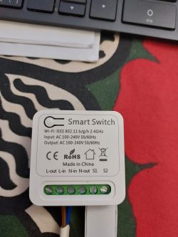
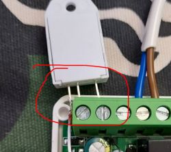
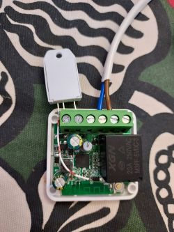
There is S1 and S2 connectors for external switch. I used those to connect DHT22 sensor. S1 is ground and S2 ic connected to GPIO P14, which is pin11 on the CPU. I just took the NC pin off the sensor. All three other pins are at suitable distance from each other to fit the connector.
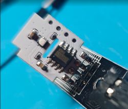
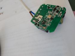
There is a pullup resistor and capacitor between this P14 and VCC. I took them both off. They are located near the relay under marking BC8.

Only VCC to the sensor needs to be addeb by jumper.
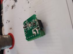
I did not desolder the CPU to flash it. One UART wire can be soldered to the BR4 resistor at the end near number 4. For the second one I used a big and sharp normal knitting needle from my wifes reserves. I holded it at the plase simply by hand. It's easier to keep it on the right spot if it is sharp enoug.
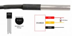
DHT22 sensor gives right values right away. I did try a DHT11 too and it seems to need some dividers to give correct value.
Here is what it looks like:
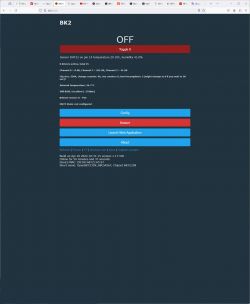
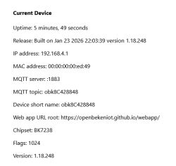
Here is configuration:
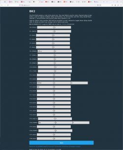
DHT22 is where originally should be BTN_TGL_ALL to act as external on/off switch.
Related T34 topic (flashing method): https://www.elektroda.com/rtvforum/topic4036975.html
For more info, see: https://www.elektroda.com/rtvforum/find.php?q=T34
Cool? Ranking DIY


