Elektroda.com
Elektroda.com
X

uProg - small, fast, portable AVR programmer with SD

manekinen 144193 364
This content has been translated flag-pl » flag-en View the original version here.
  • #271
    Sebastian.R
    Level 20  
    And how will it be in the case of the first software?
    In the config file for it there is:

    11110010 uProg settings are saved in this byte
    ||||||||
    ||||||| + ---- bit0 - file type (1 for hex, 0 for bin)
    |||||| + ----- bit1 - status bar (1 for enabled-slower programming, 0 for disabled-normal programming)
    ||||| + ------ bit2 - not original lcd (1 for chinese not-PCD8554, 0 for original PCD8544 driver lcd)
    |||| + ------- bit3 - slow SPI clock for LCD (1 for 2MHz, 0 for 4MHz)
    ||| + -------- bit4 - speed-up programmer clock (1 for max speed up to 16MHz, 0 for fabric 8MHz)
    || + --------- bit5 - show anims (1 to play animations after failed programming)
    | + ---------- bit6 - auto erase (1 to erase the chip before programming flash memory)
    + ----------- bit7 - auto verify (1 to autoverify flash or eeprom after flashing)


    bit2 and bit3 but after switching it does not give anything.
    Immediately after turning on, I have:
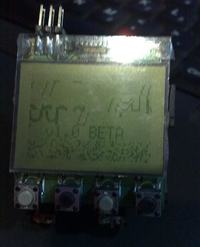
    uProg - small, fast, portable AVR programmer with SD
    You gave the link but to the config to the firmware higher than the first version, which is the only one for me. But thanks for the quick response :)
  • #272
    piotrva
    VIP Meritorious for electroda.pl
    Or maybe a friend will try new versions again?
  • #273
    Sebastian.R
    Level 20  
    Again ? Heh, I'm 99.9% sure it's the display's fault. It's just that this version is handled some other way. The first soft gives an image on the display, the next one does not, despite the settings in the config. Also, a program that could be uploaded to uProg would be useful to test pixel by pixel. It is possible that the handling speed is too high. This can not be set in the first software, and in the next ones, but what if NOTHING TO SEE (as if it did not touch the pins - but the matter is clear, as I will upload the first soft again, I have a picture like in the photos).
  • #274
    mlassota
    Level 18  
    Hello
    However, I would have suspected the contrast setting - see if the FF will not have the entire black display ... I tested it on several displays (5 pcs / 2 types, i.e. with metal and glass pads) If anything changed - it was the contrast setting ...
    Regards
  • #275
    manekinen
    Level 29  
    Is the SD card read at all? Because if setting this bit does not change anything, I suspect that it is not read at all. You can check it by entering a folder to see if there are any files. Also remember that each version of the software has different files that must be placed on the card. The 3rd version of the software flashes when you start with the diode that was added on the 1.3 board. I do not remember what tile you have, but you can solder it. When it comes to LCDs with glass pads, everyone has them, and it works for everyone.
  • #276
    piotrva
    VIP Meritorious for electroda.pl
    Exactly, it is definitely "Chinese" (in my case, the first soft looked the same), and in subsequent versions it was necessary to set the appropriate contrast. If it was the display's fault, you would NEVER see ANYTHING. Another reason is the lack of initialization and reading of the SD card - I had the same problem with the LCD when I had the wrong capacitor to boot the SD card.
  • #277
    Sebastian.R
    Level 20  
    mlassota wrote:
    Hello
    However, I would have suspected the contrast setting - see if the FF will not have the entire black display ... I tested it on several displays (5 pcs / 2 types, i.e. with metal and glass pads) If anything changed - it was the contrast setting ...
    Regards


    How to set it up in software no.1?

    manekinen wrote:
    Is the SD card read at all? Because if setting this bit does not change anything, I suspect that it is not read at all. You can check it by entering a folder to see if there are any files. Also remember that each version of the software has different files that must be placed on the card. The 3rd version of the software flashes when you start with the diode that was added on the 1.3 board. I do not remember what tile you have, but you can solder it. When it comes to LCDs with glass pads, everyone has them, and it works for everyone.

    PCB version 1.0, i.e. the first one.
    When I remove the card, there is Error, i.e. uProg responds well to the lack of a card.
    And you are 99% right, something wrong with the card because I put two softs into the catalog and ... dir empty :cry:
    Wait, I put it in the menu to read HEX and ... it works. I mean, you can see these two files.
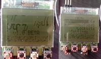
    I wonder that the inscription "v1.0 BETA" is in the right place and the graphics are shifted. In this startup picture.

    @piotrva: I have 22uF / 16V now, but before that I have 47uF / 16V and bushes too.
    What version of the software do you have now, including the glass one, which was also freaking out at the beginning?
    And what settings did you give with it? Thanks in advance :)

    All 3 sofas tested with different contrast settings. I went back to the first software. I give up.
  • #278
    adam-k
    Level 13  
    In both photos you have posted, you can clearly see that you have the display described in this link: Link
    (the last 11 pixels across the width of the display are random)
    Apart from this area, after removing the card I have the same image on the display as in your first photo, i.e. shifted menu items.
    For me, the conclusions are as follows:
    The first picture shows a working programmer with a misconfigured display type (7-bit) or a badly (un-) read config.ini configuration file.
    you could have taken the second photo while booting or the processor "freezes"
    I suggest you upload the latest soft, configure the display correctly, and if that doesn't help, look at the card or read it.
    The contrast is approximately correct, i.e. you can see the subtitles and not a blank or black screen, so there is nothing to do here and after changing the software, set it as in the first version.
  • #279
    piotrva
    VIP Meritorious for electroda.pl
    I have the newest soft, probably 1.03
    here is my cfg file:
    
    :10110111
     ||||||||
     |||||||+---- bit0 - programmer clock from osccal, zegar programatora z bajtu osccal (1 = speed from OSCCAL byte, 0 = fabric 8MHz)(1 = prędkość z bajtu OSCCAL, 0 = prędkość fabryczna)
     ||||||+----- bit1 - AUTO VERIFY (1 = autoverify flash or eeprom after flashing)
     |||||+------ bit2 - AUTO ERASE (1 = erase the chip before programming flash memory)
     ||||+------- bit3 - SHOW ANIMS (1 = play animations after failed programming)
     |||+-------- bit4 - PROGRESS BAR (1 = enabled-slower programming, 0 = disabled-normal programming)
     ||+--------- bit5 - HEX FILES (1 = hex, 0 = bin)
     |+---------- bit6 - Slower SPI clock for LCD, wolniejszy zegar dla LCD (1 for 2MHz, 0 for 4MHz)
     +----------- bit7 - LCD organization, organizacja LCD (1 = 48*102(chinese), 0 = 48*84(normal))
    
    :AF = lcd contrast, kontrast (HEX)
    80 - converter off, przetworica wyłączona
    81 to FF - contrast voltage from min to max, napięcie przetwornicy od min do max
    
    
    :14 = lcd bias, multipleksacja (HEX)
    10 to 17 - see PCD8544 datasheet, patrz nota 
    
    :8 = programming speed start, początkowa prędkość programowania (DEC)
    8 - 8MHz (default, domyślna)
    7 - 4MHz
    6 - 2MHz
    5 - 1MHz
    4 - 500kHz
    3 - 250kHz
    2 - 125kHz
    
    :FF = osccal value, wartość osccal (HEX)
    00 to FF - internal oscilator calibration from 4MHz to 16MHz, kalibracja wewnętrznego oscylatora od 4MHz do 16MHz
    
    Programmmer use values preceded by a colon. Rest of the text can be freely modified. Do not put any colon chars.
    Programator używa wartości poprzedzonych dwukropkiem. Resztę tekstu można dowolnie zmieniać. Nie należy wstawiać dwukropków.
  • #280
    Sebastian.R
    Level 20  
    I unfolded it, I corrected February and after folding it I have 1-3 lines less in the display (the situation means it has worsened). I followed the directions above and ... I had to go back to the first software. I put the second tflash card (without the SDHC inscription - uProg does not support these) with a capacity of 2GB, I put files adequate to the atmata software, but it did not help me.
    Adam-K shed some light on the matter and somehow does not fill me with optimism.
    Not the card and not the installation is to blame, but only the display. If I put it in Nokia, 99.9% would be no problem with it.
    The uProg card reads because it sees the inserted files. And since the inscriptions and graphics are in the wrong places ... it's difficult. Shit happens.

    uProg - small, fast, portable AVR programmer with SD


    And could the first soft be written again for these glass displays (not original)? But only the first soft that works for me would be modified. Would it be possible?
    Following these tips:
    Link of course :|

    In about 2 hours a friend will bring me an old Nokia 3310 (or 3330 - I don't know), so I will see if my display is "handicapped" and if I am wasting my time unnecessarily.
    When I look at the Manekinen avatar, I also have the inscription "v1.0 BETA" elsewhere.
    I found a display for Nokia 5110 on ebay for PLN 20 with shipping (i.e. matching) but made on a PCB with backlight ... and now I wonder because it is cheap compared to allegro.
    uProg - small, fast, portable AVR programmer with SD
    Compatible with PCD8544 Link
    What else I noticed is that animations are not displayed even though I will select ON next to Show Anims.
  • #281
    manekinen
    Level 29  
    To make sure the config.ini file is read correctly there, you can go to options, change some settings, turn off and on, and check if the settings are loaded according to what you changed.

    adam-k wrote:
    In both photos you have posted you can clearly see that you have the display described in this link: Link

    The program sends both 0x05 and 0x06, the original and the Chinese responded well to it. Setting this bit for the display type only causes the program to send additional blank data (3 spaces) after each line to fill these phantom 102 pixels. In the photos, it looks like he doesn't do that at all. And the truncated top line of text says that byte 0x05 was not sent. Overall a strange thing.

    As for the contrast - the first version of the software did mistake , the display was improperly powered (the LCD power pin was pointing up, but it was set as input, so the display was only powered by the internal pullup in the atm?re) so the contrast adjustment in this version only produces imperceptible effects. You can try to power the display directly from 3.3V, my theory is also that at startup, the voltage on its power supply grows too slowly and the display does not receive the 0x05 byte which is sent as one of the first.

    I do not need to write about it, the system must work with soft 1.3, this first version has a lot of errors compared to the newest one, just read the changelog :)
  • #282
    Sebastian.R
    Level 20  
    I uploaded and (_Y_). Absolutely NOTHING on display. A friend brought a phone, but here too, because the phone was damaged (by my friend's son), I am also unable to check the display. I have uploaded the soft first to come back. What I noticed is that it does not play anims, if I want to flash, uProg does a reset (atmel not connected to programming) and it should probably display a message like on the card.
    I am also wondering whether to buy this display for PLN 20, but if I do not know if something has already happened to the atmega328P, I do not know if it makes sense at all to deal with the threshold.
  • #283
    manekinen
    Level 29  
    Sebastian.R wrote:
    I have uploaded the soft first to come back. What I noticed is that anims are not playing

    Software bug, described in changelog.
    Sebastian.R wrote:
    if i want to flash uProg does a reset

    Do you have the SLFPRG jumper shorted?
    Again, this is the BETA version, it has a lot of bugs.
    I also asked if version 1.3 is blinking at startup, have you not checked? Check the voltages, if they rise, check the CLKO pin, if there is a 2-4mhz waveform (depending on your oscillator speed. Also set the speed of the system to the default in config.ini, ie 8mhz without OSCCAL).

    You have displays on the Allegro for PLN 14 and with shipping LINK
  • #284
    Sebastian.R
    Level 20  
    OK, first I will convert the board from 1.0 to the higher version ;)
    And I ordered a second display.
    Kruca fix, this LED flashing where should it be, because resistors 221 = 220 ? (I could 221 or 471, I gave the first ones) already soldered? I have reviewed on your website how to upgrade to v1.1 and only about resistors ... there is nothing about the diode. I am aware that it is on a PCB for soft v1.3 but I have a v1.0 board.
    It is probably the 7th pin of the t-flash card? How do I give a diode plus 221 resistor will be ok?


    Approx. I soldered and in this version of the software, after the start, the card will flash twice (it reads the WELCOME logo) and then going to the Menu once. Then when you run around this menu, of course, there is a reaction of the diode when you enter the directory with soft, etc.

    With this reset it is like when I enter the flash option, it happens with a closed jumper. So normal.
    If I want to flash without an external circuit, I see "SCK: 62.5KHz p: no answer" and then the LED is blinking and an animation should appear, but only its shifted parts show. Well, if I do nothing then (I will not press the first button on the left), the picture is standing and the LED is blinking and blinking. Certainly until the battery is discharged, although I have not checked it. When I press the first key on the left, I go back to the main menu.

    I unfolded and reassembled the entire uProg. The effect is that I have another line less on the display, despite very careful treatment. These glass displays are a Chinese voyage of some kind. Biodegradable indeed :) If I lose the last line it will probably crumble or disappear :D Heh, there are so many displays and uProg "walks" on such a shit. We will see on Wednesday (?) If the PLN 14 every few days ago I invested in a second display or it was extravagance on my part (and faith in miracles).

    And I will add:
    manekinen wrote:
    check the CLKO pin if there is a 2-4mhz mileage

    I have absolutely no device like an oscilloscope or a frequency meter so no chance to check it. I will measure the tensions at whatever point you want there, but without display because I don't know how to do it with it, I mean with it on. Well, probably some thin wires are soldered. But is it not going to cause distortions and errors in the measurement? Finally, I will be touching with an ordinary Chinese-made multimeter.

    Welcome back.
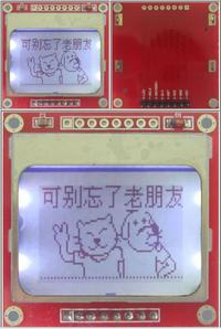
    I have the second display and I will tell you that I have miracles on each version, but not what should be displayed. It displays mostly random pixels. Sometimes it will light up to the maximum, that is, all pixels are on. But never once did I get something similar to what I get on the glass display.
    At the moment I do not have a photo, but if I have the opportunity, I will give it.
    The display is slightly different from the glass one with two capacitors, as if glued with transparent glue, and there are foil like plates stuck to the contacts. When it lights up, the shade turns purple.
    No strange coincidence. Two displays and zero success. It is possible that the system is damaged in some way. He reads the card, the LED blinks, sees the files, but I have no idea if it reads the config. Ifso that he does not read, do I have a card or will I not have the same, i.e. ERROR DIR? How can you not read the card because there is, for example, SDHC or the unsupported one, what is displayed to you? Because my card is not SDHC (sees files). Any suggestions? Thanks.

    Hmm .. I made my friend Manekinen this great atmela recuperator and it works great. I thought that this time it would be easy to walk from the very first kick. A breakdown :(
  • #285
    figaro
    Level 14  
    Hello, my problem with starting the programmer was that after uploading the software to the processor, the programmer started without a card, but everything was moved to the LCD after inserting the penalty with loaded configuration files, the programmer did not fire anymore, the problem was that I did not upload the configuration files from this version, which is necessary . After uploading the appropriate files, the programmer worked properly. It was only necessary to change the display bit in the configuration file. And it works

    To the constructor

    I think that in the future there should be a permanent battery charging system on the programmer's PCB :)
  • #286
    Sebastian.R
    Level 20  
    But if it was not so black, I will say that one thing has improved. The system is functional and the rest on the PCB - it turned out when I connected the second display. At the beginning, "fries", which means he did not show anything sensible, I would say it was worse than the first one, because it was shifted there, but the menu was there. I looked closely at the display. I noticed that it has a foil with a kind of plaque. In desperation I tore it off and cleaned the contacts. I decided to make an adapter on the PCB so that I do not touch the display anymore. I noticed that the factory display has 9 pins. Through this foil, it could be connected like the one with 8 pins. I thought that there was something wrong with these contacts, so breaking the foil turned out to be justified later. I made an adapter, instead of metal contacts I gave a conductive eraser, I made the connection to the uProg PCB with 8 wires (the HDD tape was helpful). Everything fired as it should on the 1.0 software. As you can see in the photo. On others, unfortunately, nothing wanted to be displayed (which would not change in the config). So I will probably stay with the first software.
    uProg - small, fast, portable AVR programmer with SD

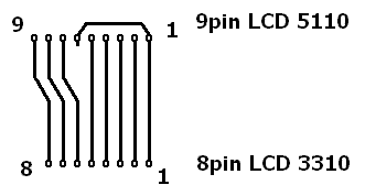
    LCD adapter to fit 8 pin:
    uProg - small, fast, portable AVR programmer with SD

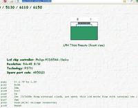
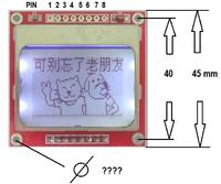
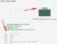
    The difference is that in the LPH7366 on pin 6 we have an input for a 32K (watch) oscillator, but that there is such an oscillator inside the LCD system, we connect this pin to the LCD power supply through a small resistor - I gave 10?.
    We can omit this pin connected to Vcc_LCD, connect the rest directly as 8. Nothing needs to be swapped, just shift from 7-9 to match 6-8 (1-4 is the same as in LPH7779 / 7677).

    Question: why does it not work on other soft devices, although the t-Flash card is reading? I mean the files he sees.

    I decided to make an additional system that will allow you to connect another LCD, e.g. based on the T6963C. On some attiny / atmega controller. I will let you know when something is known. And it will work.
    Well, such a gateway for those who would like to connect a 16X2 display. No changes to your project - program. Only the display is different.
  • #287
    snapper1234
    Level 11  
    hello, i am from germany, also i write in english.

    any questions to uProg v1.2 with NOKIA 3310 LCD :

    other (Nokia) displays e.g. 5110 also usable ?

    works other cpu, e.g. atmega168 or lower in the unit ?

    kind regards

    p.s. license breach ---->

    http://www.ebay.de/sch/good4pay/m.html
  • #288
    piotrva
    VIP Meritorious for electroda.pl
    The LCD should be based on controller LPH7779/7677.
    Other CPU aren't supported.
  • #289
    Sebastian.R
    Level 20  
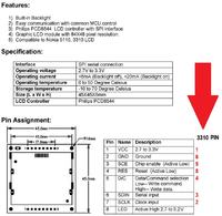
    LCD from 5110/5130/6110/6150 should fit but need a modification (see my earlier post).
    LCD from 3210/3310 & 3330 should fit without modification.
    As for this link on ebay ... Manekinen should define what to do, because the construction is his, so the seller should fire him a plot :) .
  • #290
    snapper1234
    Level 11  
    hello and thx for the information,
    i am working on a new layout for 5110 display,
    it is better to solder and easier to buy,
    I also like the setup with the pcb !
    i add ET1117-3.3V regulator and make the pcb bigger, 50x50mm !
    how big the holes in the 5110 pcb ?
    using lcd-vcc pb7 and sd-vcc pc0 pd2+3 from the Atmega or from the 3.3V regulator ?
    what changes do I need to pay attention to?
    Please the information in english,
    the translation Polish to German language not work so well!

    regards


    uProg - small, fast, portable AVR programmer with SD uProg - small, fast, portable AVR programmer with SD
  • #291
    Sebastian.R
    Level 20  
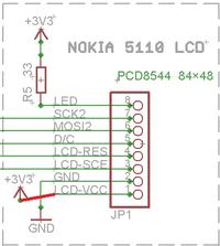
    LCD 5110(pin 9) - 6pin are input clock 32K , if will use internaly clock 32K put this pin connect to Vcc .
    See picture :
    uProg - small, fast, portable AVR programmer with SD
    For me this combination works.
  • #292
    snapper1234
    Level 11  
    I somehow do not understand, 5110 is 8-pin!

    uProg - small, fast, portable AVR programmer with SD

    uProg - small, fast, portable AVR programmer with SD

    uProg - small, fast, portable AVR programmer with SD
  • #293
    Sebastian.R
    Level 20  
    snapper1234 wrote:
    i am working on a new layout for 5110 display,

    Oryginal LCD for 5110 has a 9 pins.
    See:
    uProg - small, fast, portable AVR programmer with SD

    That i see -You bought an adapter. Good! I wanted to buy this display, because the previous lcd would not work properly. Link
    He has written pinout. Now , You can connect it to the uProg using the description of the display to the Nokia 3310.
    uProg - small, fast, portable AVR programmer with SD

    You not sure where to connect the pin 7 (Vout) ? Leave it unconnected ensure these capacitors inside (adapter with LCD) have been placed.

    PS.
    OK
  • #294
    manekinen
    Level 29  
    Sebastian, I am aware of this, this is not the first and not the last asshole trying to get away with someone else's work. The matter has been reported and I am waiting for the reaction of this website. Please don't blow stuff like that here, because that's not the right topic for that :)
  • #295
    piotrva
    VIP Meritorious for electroda.pl
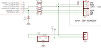
    Dear snapper1234, have You seen my solution of power supply?
    uProg - small, fast, portable AVR programmer with SD
    Maybe this solluton will be suiting for Your modification.
  • #296
    snapper1234
    Level 11  
    uProg - small, fast, portable AVR programmer with SD

    hello piotrva
    yes, the picture I've seen,
    I just do not understand the function,
    the translation Polish to German language not work so well!
    I need a translation with a unique function
    of the jumper to 1. 2. ....e.g.

    kind regards
  • #297
    Sebastian.R
    Level 20  
    First position - if in use Vcc (5V) power supply to programmable controller
    Second position - if in use Vcc (3V) -power supply from L1117-3.3
    Third position (without jumper) - if use CLK0 only, need use external power supply to programmable controller.

    @manekinen: You had to write the menu in Polish, what's interesting if the seller handled it? But, now it's "by the way".
  • #298
    snapper1234
    Level 11  
    hi

    what I generally do not understand is the power supply
    for the display and the sd card,

    SD-VCC with PC0, PD2/3 to the SD Card
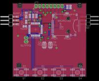
    and VCC display via PB7?

    why not use the 3.3V directly from the L1117-3.3 ?

    greetz
  • #299
    Sebastian.R
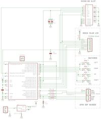
    Level 20  
    snapper1234 wrote:
    SD-VCC with PC0, PD2/3 to the SD Card
    and VCC display via PB7?

    Right!
    Card and LCD Display draw so little current that can be directly supplied from the microcontroller PINs.
  • #300
    snapper1234
    Level 11  
    thx, in other words:

    if I supply sd and 5110 directly with the 3v3 from the regulator ,
    save 4x uC ports and uC code!
    R2 --> PB0 is the automatic recognition whether 5V coming from isp?
    and D1 3v3 is for ...... ?

    greetz