logo elektroda
logo elektroda
X
logo elektroda

uProg - small, fast, portable AVR programmer with SD

manekinen 154831 364
ADVERTISEMENT
Treść została przetłumaczona polish » english Zobacz oryginalną wersję tematu
  • #241 10166894
    marcin44430
    Level 16  
    Happy Uprog started, I played, turned on and off, and finally the whole screen lit up, so I reduced the contrast and turned on again and the gun. :D :D :D :D :D
  • ADVERTISEMENT
  • #242 10173603
    marcin44430
    Level 16  
    I had a little fun with it and I think I found a bug. Well, if we run the upgrade without the chip connected and enter flash-> read, the animation does not appear, only vertical stripes, but the next times are fine.


  • ADVERTISEMENT
  • #243 10209352
    mirobo
    Level 12  
    Hello.
    THANK YOU manekinen
    Great project - great thing :D - I use the device "regularly" :wink: .
    I've needed something like this for a long time, so thanks again.

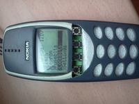
    For me, it's a portable device, so I stuffed it into this:
    uProg - small, fast, portable AVR programmer with SD

    Minimally difficult access to buttons - no accidental activations in the pocket :wink:
    There is "a lot" of space under the keyboard where you can add something (e.g. battery charging system etc.)

    Now the programmer is powered by the original Nokia battery, which I charge when needed in another phone. But time will come for modifications :wink:


    [edit]
    Ps.: I do not have a battery voltage measurement (waiting for update), but I noticed that when turning off the programmer with the button LE for a fraction of a second, instead of 1.1V, the voltage of 3.3V appears on the display ... is this a substitute for a change, or some "miracles"?
  • #244 10211204
    manekinen
    Level 29  
    marcin44430 wrote:
    I had a little fun with it and I think I found a bug. Well, if we run the upgrade without the chip connected and enter flash-> read, the animation does not appear, only vertical stripes, but the next times are fine.

    Such a thing happened for me when there were no files with the appropriate bitmaps on the card. Does this only happen with flash> read? Have you tried reformatting the card and reloading everything?

    mirobo wrote:
    Ps.: I do not have a battery voltage measurement (I am waiting for the update), but I noticed that when turning off the programmer with the LE button for a fraction of a second instead of 1.1V, I see 3.3V on the display ... is it a substitute for a change or some "miracles" "?

    If you look at the animation folders you will notice that this "3.3V" is just on the bitmap, both on and off :) And it looks pretty good in the housing from the 3310, but tell me why you didn't use the original buttons? After all, it was easy to use them - like a glove, up and down ok and cancel :) I also noticed in the video that the vibration of the contacts can be felt - are they just some occasional cases?

    As for the voltage measurement ... on the new board, the voltage is not measured, so it is 1.1V. During switching on, the programmer checks the voltage and if it is below 3V, it waits for additional time to charge the capacitor from the memory card - hence the long start-up.

    I started working on this PDI but unfortunately I gave it up so far due to lack of time. But I will try at least to throw in a version that will improve, among others, voltage measurement and other minor errors.

    I would like to inform you that as of today I only have 15 free tiles left for resale, and I WILL NOT order more tiles. So if anyone is still delaying and would like to build a system, let him stay awake ;)
  • #245 10212135
    mirobo
    Level 12  
    manekinen wrote:

    If you look at the animation folders you will notice that this "3.3V" is just on the bitmap, both on and off :) And it looks pretty good in the housing from the 3310, but tell me why you didn't use the original buttons? After all, it was easy to use them - like a glove, up and down ok and cancel :) I also noticed in the video that the vibration of the contacts can be felt - are they just some occasional cases?


    Heh :D - the blind are not sown :wink: - I didn't notice it on bitmaps, and the voltage was right for me - hence the "miracle".

    As for the housing - I was thinking about using the original buttons (then you have to desolder the buttons from the board, because they do not fit), but I only had the housing without the keyboard, so it turned out that way.

    However, as for the vibration of the contacts, it is probably the fault of the video itself and its quality (the programmer in one hand and the phone in the other), because there is no problem with it.

    I have one more question: Would it be possible to add 4-5 subfolders in the flash folder and then select the file?
  • #246 10212819
    manekinen
    Level 29  
    Ie. first select the flash folder and then the correct file? Hmmm, it is possible, but it will require a lot of rework and a lot of code enlargement. So such a gimmick is unlikely to arise.
  • #248 10213614
    piotrva
    VIP Meritorious for electroda.pl
    How is Paweł working on PDI? Have you figured out the documentation?
  • #249 10294240
    figaro
    Level 14  
    Hello,
    At the beginning, I bow my head to the designer, the design for 6+, in my case very helpful in the service, but after using the programmer for a long time, I noticed two major disadvantages:
    1 - no possibility to delete the file created by the programmer after reading from the processor, you need to remove the card and edit it in the PC
    2 - if we have several different batches for the same processor, I must honestly say that I get lost and I have a problem which file to choose - "no possibility to describe the file" info.

    The charging system, which is included in this post, should land permanently on the PCB, which is perfect.

    I wish you all
    Healthy and happy holidays :D
  • #250 10295353
    manekinen
    Level 29  
    soft 1.3 wrote:
    o added file deletion function - select a file and while holding the LE button press the RI button. Release the LE button to exit.


    And as for the file descriptions - how do you imagine it? As I wrote in the description, the files must be named so that you can easily distinguish them later :) The design of the system has some limitations that cannot be overcome.
  • #251 10312325
    figaro
    Level 14  
    Thanks for the tip on deleting files.
    If it is possible to edit the file names then I have no more questions.
    The only downside is that you can do it from a PC :(
  • #252 10370864
    SQ9MYX
    Level 23  
    Hello.
    What should I do for the programmer to handle the Attiny25 prock. At the moment, when trying to write, the progressbar comes to an end, but the proc remains empty. checked on several procks .. maybe some configuration should be added? Best regards and I count on your help ..... Piotrek SQ9MYX

    Added after 3 [hours] 12 [minutes]:

    and one more problem ... by throwing the HEX file on the memory card which is programming my Attiny25 via USBASP and trying to write it, I get the message 'file too big' and the file has 1kb :(

    Added after 9 [minutes]:

    in the attachment hex files ... the file that I have to load (save.hex) and the file read from the prock.
    It follows that it also does not read it to me because the file is empty FF itself
  • #253 10374162
    manekinen
    Level 29  
    ukffun wrote:
    and one more problem ... by throwing the HEX file on the memory card which is programming my Attiny25 via USBASP and trying to write it, I get the message 'file too big' and the file has 1kb

    Hmm, somewhere in the code there must be a mistake in calculating the size of these HEXs, a Russian already reported to me that he could not program attina13 with the hex. This probably applies to small procks. Unfortunately, I don't have time to deal with it.

    I tested the circuit with attiny45, and I can see that the setting in the file is the same (of course the memory size is set for 4kB procks), so theoretically, there should be no problems.

    See if BIN works normally, something will be known :)
  • #254 10375573
    SQ9MYX
    Level 23  
    Bin, unfortunately, also does not go ...
  • #255 10377528
    manekinen
    Level 29  
    Ok, I'll try to find some time to research what's up in the grass.
  • ADVERTISEMENT
  • #256 10378713
    Karol966
    Level 31  
    I wanted to build this sensational layout for myself, but unfortunately it didn't pop. I have no way of communicating with Prock. I am using USBasp + avrdude + avrdude GUI. I can not set the coffee grounds or load the load. The signature it reads is 0x535353.
    Maybe I'm doing something wrong. During programming, I powered the system from a separate 3.3V / 5V power supply, I gave the voltage from the programmer or not and still nothing. Resistors I soldered:
    R1 - 330
    R2 - 1k (its value puzzles me a lot, write how you can what is the meaning of this Prock line, it is on the VCC pin of the ISP 6PIN socket)
    R3 - 330
    R4 - 330
    The programmer is 100% functional, I use the SLOW_SCK jumper during communication.
  • #257 10382361
    adam-k
    Level 13  
    I had the same, but I also have the STK 200/300 programmer and it solved the problem.
    So I wasn't looking for the reason and I can't say why it is, but STK
    you will stick together in five minutes.
  • #258 10382754
    marcin44430
    Level 16  
    And did your colleague close the fields I marked in the picture?
    uProg - small, fast, portable AVR programmer with SD

    Added after 2 [minutes]:

    PS The R2-1k line is the auxiliary clock signal.
  • #259 10384219
    Karol966
    Level 31  
    No exaggeration, buddy marcin44430 ;) I'm not such a novice. If the name itself does not indicate what this jumper is for (SELFPROG), then there is still a diagram showing that it is a connection of the RST line of the processor with the programmer socket. However, if I did not put this jumper on, how would I read the processor's signature (no longer important that it was a bad one)? ;)
  • ADVERTISEMENT
  • #260 10384887
    mirobo
    Level 12  
    Karol966 wrote:
    I can not set the coffee grounds or load the load. The signature it reads is 0x535353.


    I had something similar. After changing avrdude to version 5.8, prock programming surprised.
  • #261 10385092
    Karol966
    Level 31  
    mirobo wrote:
    Karol966 wrote:
    I can not set the coffee grounds or load the load. The signature it reads is 0x535353.


    I had something similar. After changing avrdude to version 5.8, prock programming surprised.


    I only use this version.
  • #262 10385272
    mlassota
    Level 18  
    Hello
    Buddy, how do you power the system? Through the ISP plug or through the "pads" supplying the uProga board? There is no VCC on the ISP plug - there is a clock signal on this pin - hence the 1k resistor to avoid a possible conflict of states ...
    If this is obvious to you - then I am sorry but this possible reason came to my mind (I was reading the wrong signatures at the feed shoulder - i.e. the power was taken from the data line)
  • #263 10385336
    Karol966
    Level 31  
    Yes, that is also obvious to me. I power from the pads on the board with voltages both 3.3V and 5V.
  • #264 10417309
    mirobo
    Level 12  
    I had this problem today:
    Programming works flawlessly, while any reading from the prock and writing it on the card causes the loss of files. So far, it was ok. Writing to the card in the computer was trouble-free.
    It looks like that after transferring the card to the computer, there are 4-5 files on it with "strange" name and not readable. I did a few tries and still the same.
  • #265 10417527
    SQ9MYX
    Level 23  
    > mannequin Have you managed to investigate the problem of this Attina25?

    > mirobo try to increase the capacitance of the capacitor on the memory card .. the card needs a little more current when writing than when reading.
  • #266 10422938
    mirobo
    Level 12  
    Increasing the capacitance of the capacitor helped.
    On the other hand, I was a bit "lucky" that the programmer worked correctly so far - apparently the capacity was "on the verge" and it was enough that it changed a bit and errors popped up when writing to the card (reading ok).
  • #267 10474443
    manekinen
    Level 29  
    ukffun wrote:
    > mannequin have you been able to investigate the problem of this Attina25?

    Unfortunately not. For now, I don't even have time to contribute to the forum, so forgive me and don't expect any updates or support from me :(

    mirobo wrote:
    Increasing the capacitance of the capacitor helped.

    And what was the capacity before? What capacity card?
    Karol966 wrote:
    Yes, that is also obvious to me. I power from the pads on the board with voltages both 3.3V and 5V.

    Has the "problem" been resolved? In quotation marks, because it is about programming an ordinary microcontroller on an ordinary PCB, buddy, don't take it as a malice, but you have "uP" given in your specialization and you can't handle it?
  • #268 10474540
    mirobo
    Level 12  
    manekinen wrote:

    mirobo wrote:
    Increasing the capacitance of the capacitor helped.

    And what was the capacity before? What capacity card?


    C = 22uF, 2GB card and it was OK for some time. After some time, reading from the card and programming OK, while writing on the card when reading from Prock "smashed" files ...
    Since I had a spot, I soldered 100uF and everything was fine again.
  • #269 10541884
    Sebastian.R
    Level 20  
    And I have such a problem as one of the forum members.
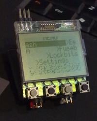
    uProg - small, fast, portable AVR programmer with SD
    The only soft that causes anything visible on the LCD is the soft with the number one. You can jump around the menu and probably also program (I have not checked). The rest of the softas cause necrosis, which would not line up.
    Anyone know the reason for this? In my opinion, this is the fault of the display. Some have glass ones too, and they like it. Fusebits set as per the instructions in avrdude.
    I guess I'm unlucky. I have the parts from the author (LCD and its connector plus capacitors, PCB). I do not have a Nokia to put a display in it, also if it is not a software defect (in this case) that can be eliminated, I give up with this project. I got horny because it would make it easier for me to fumble around with electronics and so I just wasted a lot of time to figure out what I did wrong. Soldered as it should, cleaned with acetone so that rosin was gone. Anyone advise me something?
    I will not buy a display (or a phone for the display) - it seems pointless to me. In total, I have the same chance to buy the same one and waste a lot of time to find out that I have become the owner of a second LCD that somehow does not want to cooperate as it should. Pity.

Topic summary

The discussion revolves around the uProg, a compact and portable AVR programmer that utilizes SD cards for firmware storage. Users express admiration for its design and functionality, highlighting its small size (44 x 39 x 5.5 mm) and fast programming speeds (write: 12.5kB/s, read: 14.5kB/s). Several users inquire about compatibility with various components, such as different LCD displays (notably the Nokia 3310's LPH7779), and the ability to program various AVR microcontrollers, including the ATmega328P and ATtiny series. Issues with SD card compatibility, particularly with SDHC cards, are frequently mentioned, as well as problems related to fusebit settings and display contrast. Suggestions for improvements include adding a battery charging system, enhancing the user interface, and providing better documentation for setup and troubleshooting. The community shares experiences with different configurations, troubleshooting tips, and modifications to enhance the programmer's capabilities.
Summary generated by the language model.
ADVERTISEMENT