logo elektroda
logo elektroda
X
logo elektroda

LCR-T4 electronics components tester ATMega328 - Test and Review

TechEkspert 203988 647
ADVERTISEMENT
Treść została przetłumaczona polish » english Zobacz oryginalną wersję tematu
  • #241 16675685
    logos2000
    Level 21  
    Quote:
    logos2000 wrote:
    My exeplarz did not survive the submission
    So I repeat it after Gulson: just after carefully removing the foil tester, attach / stick the display! It is on the first and second page of the story. Greetings.
    This was the first step I took, putting a thin double-sided tape under the LCD, well, that's what it is
    eurotips wrote:
    It is also possible to upload a new batch and convert it to a regular 2x16 LCD. All options remain.
    I agree, I am in the process of such modification: https://www.elektroda.pl/rtvforum/topic3372311.html#16676822
  • ADVERTISEMENT
  • #242 16675740
    gulson
    System Administrator
    logos2000 wrote:
    Is it possible to get such a display somewhere cheap? My exeplarz did not survive the folding (the black tape securing the connecting tape was peeled off), so that the screen remained dead.
    Has the tester appeared in this condition, in the sense not working? Added after 19 [hours] 50 [minutes]: OK, thanks for the response to PW, that is, theoretically damaged when trying to manipulate the tape, that's why everywhere in this product description I warn you that the case is quite delicate with this display and ribbon, but there are no other solutions on the market at the moment. That's why I took away the restriction and if you want to order it again, you have a lot of points :)
  • #243 16685557
    D214d3k
    Level 39  
    I am thinking whether or not the tester should pack any 4-section isostata so that the 3 sections will clutch all inputs together when connecting an unloaded capacitor. The fourth would run. ---- Separated from the subject: Gadżetomania by gulson on 08 Sep 2017 08:44:12
  • #244 16686634
    CMS
    Administrator of HydePark
    D214d3k wrote:
    I am thinking whether or not the tester should pack any 4-section isostata so that the 3 sections will clutch all inputs together when connecting an unloaded capacitor. The fourth would run.
    I think the idea of protecting against a charged condenser is great. However, the idea and the implementation is pointless. 1. The contact strength of the "izostat" is very small, if I remember correctly it is max 500mA. How do you think how many times you can discharge the 100uF-1000uF capacitor charged to several dozen or more Volts before the contacts weld together? As for my eye, this may happen the first time. 2. As one of my colleagues wrote, there is a good chance that the tester will recognize this as a jumper (unless we press very slowly) and start the calibration mode. I think, however, that my solution, presented a few pages earlier, is much more practical. ---- Separated from the subject: Gadżetomania by gulson on 08 Sep 2017 08:44:12
  • #245 16686721
    krzysiozak
    Level 39  
    CMS wrote:
    I think, however, that my solution, presented a few pages earlier, is much more practical.
    Maybe even the number of posts! Such thoughts on the subject of the tester: I think that the tester should first examine whether there is voltage at the tester terminals. If it is, then it should attach a suitable discharging resistor. If it turns out that the voltage does not drop, for example, by mistake connected power supply, stop further tests with an appropriate message. If it falls, unload them completely and proceed to further tests. ---- Separated from the subject: Gadżetomania by gulson on 08 Sep 2017 08:44:12
  • ADVERTISEMENT
  • #246 16686760
    398216 Usunięty
    Level 43  
    CMS wrote:
    The load capacity of "izostat" contacts is very small, if I remember correctly, it is max 500mA.
    There are also "network" isostats - dependent and independent with a greater load capacity. 2A is the minimum. "zaspawają" do not zaspawają - faster burn. Yes, but I have not seen one with eight leads in my career. However, I do not exclude their existence. Anyway, unloading more capacity charged to dozens of volts, directly through the contacts I consider a stupid idea. For this in my "extension" to the tester I have, apart from various stands, two pieces of steel wire in a copper sheath, and a high-power resistor connected to it and a relatively small resistance (I do not remember right now, maybe 10? or maybe 3.3?, but probably the first). ---- Separated from the subject: Gadżetomania by gulson on 08 Sep 2017 08:44:12
  • #247 16686774
    Jawi_P
    Level 36  
    Only what is this isostat to do? Because if there is a fear that I will forget to discharge the condenser, how come the conviction that I will not forget to press the isostat? Then, the project of the "reminder of the isostat" will be created :) ---- Separated from the subject: Gadżetomania by gulson on 08 Sep 2017 08:44:12
  • #248 16686821
    D214d3k
    Level 39  
    Well, it would work without pressing. I join the request for a post number with this better method. ---- Separated from the subject: Gadżetomania by gulson on 08 Sep 2017 08:44:12
  • #249 16686862
    CMS
    Administrator of HydePark
    CMS wrote:
    The load capacity of "izostat" contacts is very small, if I remember correctly, it is max 500mA.
    There are also "network" isostats - dependent and independent with a greater load capacity. 2A is the minimum. "zaspawają" do not zaspawają - faster burn. Yes, but I have not seen one with eight leads in my career. However, I do not exclude their existence. Anyway, unloading more capacity charged to dozens of volts, directly through the contacts I consider a stupid idea. For this in my "extension" to the tester I have, apart from various stands, two pieces of steel wire in a copper sheath, and a high-power resistor connected to it and a relatively small resistance (I do not remember right now, maybe 10? or maybe 3.3?, but probably the first). Added after 1 [minutes]:
    D214d3k wrote:
    Well, it would work without pressing. I join the request for a post number with this better method.
    The point is to replace the original button with an isostate. No post ... https://www.elektroda.pl/rtvforum/topic3354445-150.html#16600713 ---- Separated from the topic: Gadżetomania by gulson on 08 Sep 2017 08:44:12
  • #250 16686948
    398216 Usunięty
    Level 43  
    Why eight contacts? Squeezed - compact contacts 1 and 2 (you only need to make extra money - how to process it all over again - contacts only for measuring electrolytes). Pressed - measurement. The simplest solution to me - of course, if it is already to beostat. Because the simplest and not requiring too much interference would be under the measuring base attach to the housing a piece of copper wire ... And then just remember to let the capacitor into the socket short for a moment its contacts on this "instrument". :) ---- Separated from the subject: Gadżetomania by gulson on 08 Sep 2017 08:44:12
  • #251 16687095
    huluk
    Level 32  
    Thank you very much, tester yesterday has arrived, folded, checked, works great! Unfortunately, my joy of the first evening launch has somewhat disturbed the "other half" ... ;) I assembled quite late - glanced at what I fit and turn, asked, or a long time ... And when I, excited, calibrated, first tests and almost in ecstasy wanted to boast what a great gadget and how nice shows what connected - she said: "I see, it's green, turn off the light and go to sleep." Ah, these women ;)
  • ADVERTISEMENT
  • #252 16687269
    bestler
    Admin of DIY, Automation
    We connect with you in pain ... ;)
  • #253 16687631
    gumisie
    Level 43  
    huluk wrote:
    a great gadget
    huluk wrote:
    shines green
    huluk wrote:
    Turn off the light and go to sleep
    huluk wrote:
    Ah, these women
    Are you surprised?. You have a new cool gadget glowing green, jump under the quilt .... :D Greetings.
  • #254 16688043
    Adamcyn
    Level 38  
    vodiczka wrote:
    Is it possible that a long unused capacitor "pretends" two diodes connected in series cathode to the cathode?
    I had it too. The reason was the high leakage of the capacitor, but only in one direction.
  • #255 16689487
    huluk
    Level 32  
    And just - someone has it on hand and can check if the tester will recognize (and draw) a warikapa correctly?
  • #256 16689532
    DiZMar
    Level 43  
    huluk wrote:
    And just - someone has it on hand and can check if the tester will recognize (and draw) a warikapa correctly?
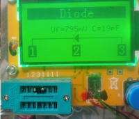
    No problem but as a simple diode. I only had one kind. LCR-T4 electronics components tester ATMega328 - Test and Review
  • #257 16689591
    Adamcyn
    Level 38  
    huluk wrote:
    will the tester recognize correctly (and draw) a warikap
    It can not draw, because warikap is a diode all the time - with a certain change in capacity versus voltage.
  • #258 16689600
    huluk
    Level 32  
    In other words, it is not very correct because we do not know if it is a rectifier diode, Zener or warikap :-| EDIT: @Adamcyn - that's what I meant, during the measurement the program will note that the capacity changes depending on the voltage applied and instead of the "normal" symbol, the diode will display an additional line or some other symbol indicating that it is waricap.
  • #259 16689604
    DiZMar
    Level 43  
    huluk wrote:
    In other words, it is not very correct because we do not know if it is a rectifier diode, Zener or warikap :-| ...
    Such a "wise" tester is not.
  • #260 16689618
    huluk
    Level 32  
    Maybe someday someone will be able to "push" additional diode functions into the program - they are often so small that there are no markings or they are obliterated and illegible and it would be good to know whether it is Zener and how much V (as it is known that Zener is it is possible to measure the voltage separately) or warikap ... what would not be used as a rectifier ...
  • ADVERTISEMENT
  • #261 16689629
    Adamcyn
    Level 38  
    huluk wrote:
    the capacity changes depending on the voltage applied
    This is the case in every connector diode, but in a more defined way in a varikap. Added after 1 [minutes]:
    huluk wrote:
    it would be good to know if it is Zener and how much V (as it is known that Zener, it is possible to measure the voltage separately),
    I do not see a problem here.
  • #262 16689813
    rafcio_21
    Level 29  
    It is worth to upload a new soft to this tester. There is a menu option to test resistors and capacitors on a regular basis, i.e. we do not have to press the button to insert one capacitor and the tester shows the result until it is removed from the stand and inserting the next result immediately. It seems to me that it better identifies triaks. After light hardware modifications, zener diodes and stabilizers can be measured. In general, I recommend to combine with the soft.
  • #263 16689827
    DiZMar
    Level 43  
    rafcio_21 wrote:
    It is worth to upload a new soft to this tester. The menu has the ability to test capacitor resistors and coils on a regular basis, i.e. we do not have to press the button to insert one capacitor and the tester shows the result until it is removed from the stand and inserting the next result immediately ...
    Not immediately after the time needed for the test. It only saves you from pressing the button. The test time will remain unchanged. Modification without specific positives. In addition, there is a risk that the test will automatically start at the wrong time and you will have to wait until it's over, which will make it even more annoying than having to click.
  • #264 16689843
    rafcio_21
    Level 29  
    But this test time is shorter than when you press the button. In addition, in the old disc, it hardly identifies, for example, the potentiometer does not have this problem with displaying the result of the second example how to insert the diode and resistor connected in series and these three points to the tester on the old disc will detect 2 diodes and the new will correctly detect the diode and resistor. In general, there are more pluses with the tester colleague before modification and the second one after modification and we compared the results, when measuring transistors, it displays more data the same measurement of the inductors. I do not regret being a bit happy with the new software.
  • #265 16693035
    Stanley_P
    Level 28  
    huluk wrote:
    In other words, it is not very correct because we do not know if it is a rectifier diode, Zener or warikap :-|
    Hello. I think I've already written here - some colleagues have too high expectations from this type of testers. Maybe in addition to detecting the type of element, the tool should give the exact type / symbol (eg BC337), display the catalog note, find the store with the lowest price? ;) The T7 tester, which was already in topic, allows you to check Zener diodes up to 30V. For this purpose, it has a built-in voltage converter of approx. 40V. However, the diode must be connected to specially provided terminals, in addition in the right direction. How else should the device determine what voltage the diode starts to conduct in the blocking direction? A similar functionality seems to have "modified" versions of the tester discussed in this thread. I believe that this type of devices in practice are more suitable for confirming the efficiency of the elements we know, than "detecting" any unmarked, unmarked piece of wood from the drawer (I mean mainly semiconductors). So when we know, or we are convinced, to a degree that borders with certainty, that we are testing specifically eg the bipolar transistor npn. By the way of repairs, when somewhere on the table "wandering" element unmarked, as to which type / type I'm not sure, even when the devices seem to be efficient will be directed to the basket ;)
  • #266 16693801
    vodiczka
    Level 43  
    Stanley_P wrote:
    Maybe ... to display a catalog notice, find a store with the lowest price?
    All it takes is to repair the damaged item and give a one-year warranty :)
  • #267 16698826
    Adamcyn
    Level 38  
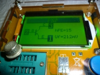
    Darlington Measurement BC516: LCR-T4 electronics components tester ATMega328 - Test and Review and a little less of a "lively" older single friend: LCR-T4 electronics components tester ATMega328 - Test and Review
  • #268 16706816
    Adamcyn
    Level 38  
    I have a question: What are your experiences when it comes to measuring inductance? So far, not enough information on this topic.
  • #269 16706997
    vodiczka
    Level 43  
    Adamcyn wrote:
    So far, not enough information on this topic.
    I handed: At the end of the test results of the Mf-102 phono cartridge. As far as I remember correctly, the nominal resistance of the coils of one channel is 660? and the inductance is 550mH. I measured: L - 668? and 541mH; R- 638? and 595mH I do not have an inductance meter so I could not compare.
  • #270 16707449
    Jawi_P
    Level 36  
    I measured the inductance ready, from the store, so I can refer to what the manufacturer wrote on them, the measurements did not differ from the declarations more than 4%.

Topic summary

The discussion revolves around the LCR-T4 electronics components tester, which utilizes an ATMega328 microcontroller. Users share their experiences with the tester's capabilities, including automatic detection of component types, measurement of inductance, capacitance, and resistance, as well as calibration procedures. Concerns are raised about the accuracy of measurements, particularly with low inductance values and the tester's ability to identify certain components like transistors and diodes. Users also discuss the power supply options, including the use of 9V batteries versus rechargeable alternatives, and modifications to improve functionality. The conversation highlights the tester's utility for hobbyists and its limitations in professional applications.
Summary generated by the language model.
ADVERTISEMENT