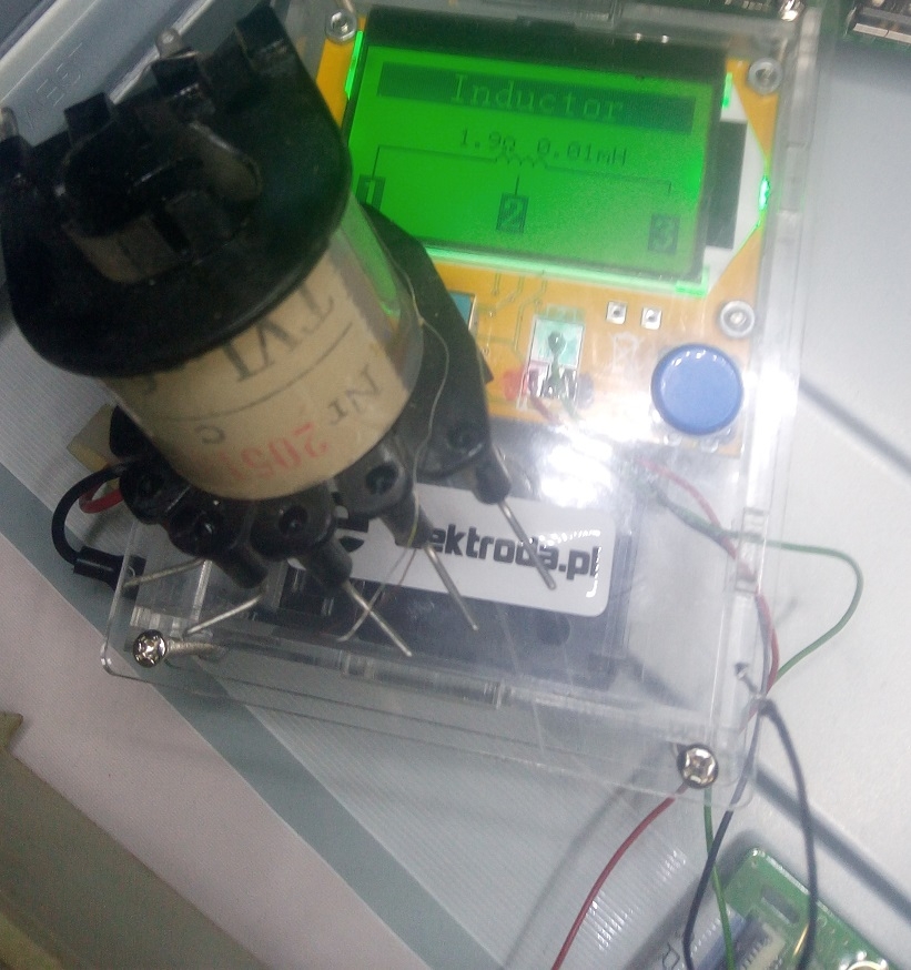
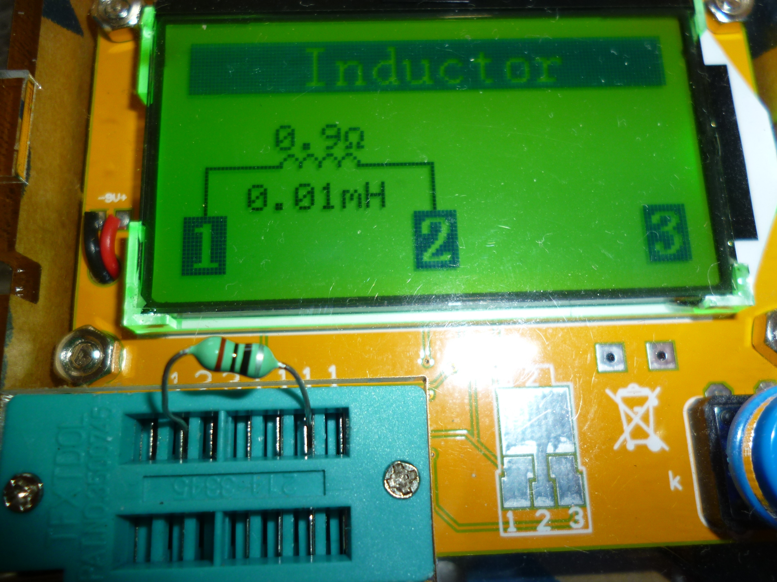
See here. Quite a good coil and no inductance? 



Czy wolisz polską wersję strony elektroda?
Nie, dziękuję Przekieruj mnie tam
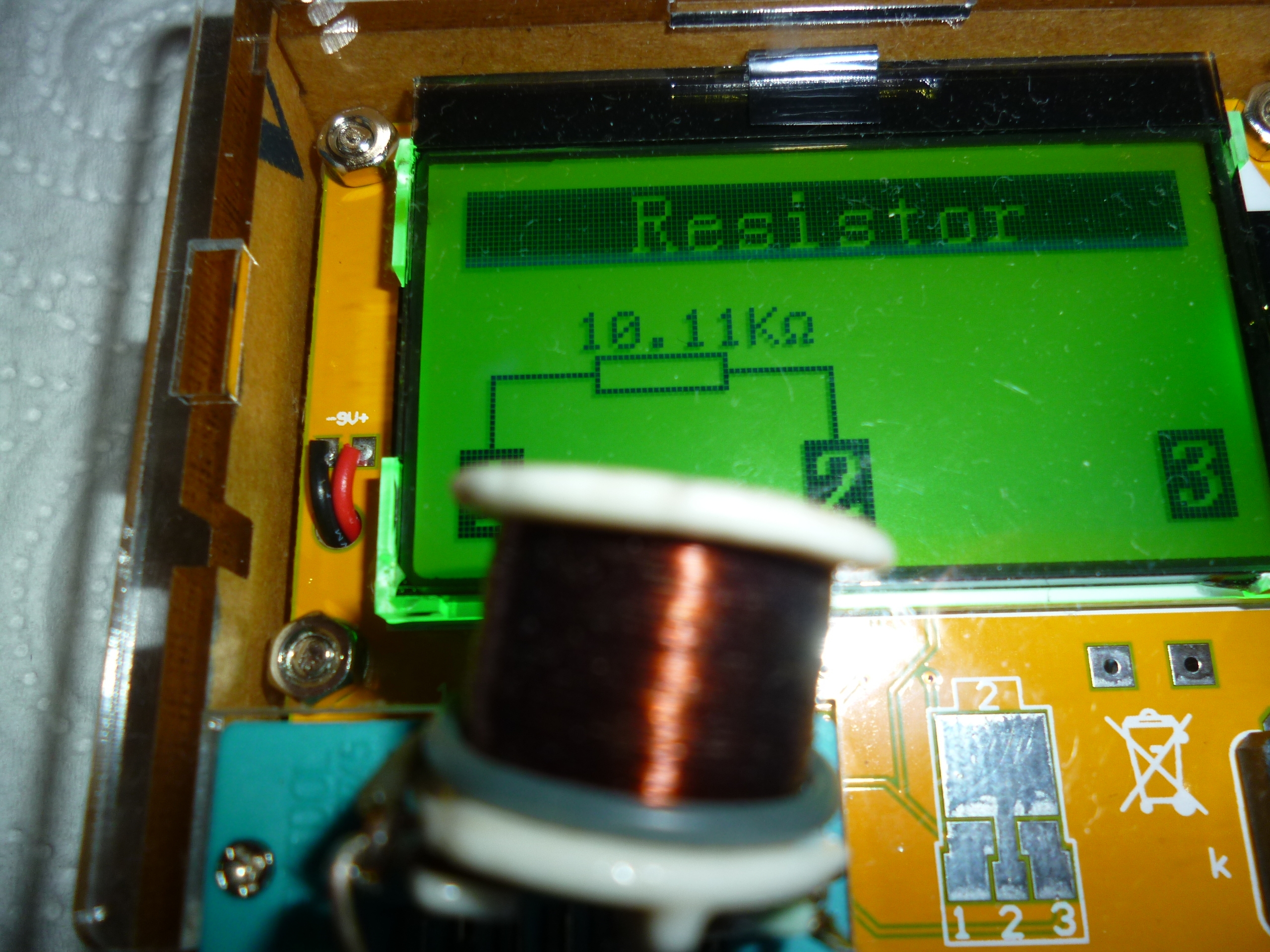
Adamcyn wrote:High resistance and considered it was just a resistor. The inductance usually has a low resistance, although not necessarily. This is the case with primary windings of low power network transformers. I noticed that too.See here. Quite a good coil and no inductance?
Adamcyn wrote:I also noticed that it does not recognize inductance in coreless coils.Quite a good coil and no inductance?
DiZMar wrote:At low resistance too. In my opinion, the proportions of resistance and inductance decide.High resistance and considered it was just a resistor.

vodiczka wrote:According to its (tester) technical data, it measures the inductance from 0.01mH. A few or even tens of coils without a core are probably less than 0.01mH. My coil with 0.01mH inductance (lower measurement limit) has been detected. If it was half as long as it had a coil it would probably be only a resistor of about 1?How not how. I did not add that she did not recognize small inductance. I wrapped the coils for several dozen turns and a resistance of 0.2-0.5?, the tester recognized the resistors.
398216 Usunięty wrote:It's just a gadget. We do not discuss accuracy, but rather that it distorts certain elements. A cheap tester has the right not to recognize many elements but it is not right from the capacitor to make a diode from a low-inductance coil, a resistor. With such errors, he ceases to be a tester and becomes a toy. A very nice toy.Gentlemen ... Do not demand from the cheap TESTER the quality and accuracy of measurements such as in decent bridges or transistor meters. It's ONLY TESTER,

brofran wrote:But it displays the appropriate message when it is unable to diagnose the item. The problem is that some elements are unable to diagnose and others diagnose as "otherwise efficient"Consent, but if an element is not able to diagnose, it should display the appropriate string, e.g. unknown.
DiZMar wrote:You probably are right, I will not check the inductance meter.A few or even tens of coils without a core are probably less than 0.01mH. My coil with 0.01mH inductance (lower measurement limit) has been detected. If it was half as long as it had a coil it would probably be only a resistor of about 1?
Adamcyn wrote:Hm, I can wind coils about 0.01 mH based on the calculator below and give what the tester pointed out. http://ekalk.eu/l_pl.htmlMaybe we'll be back to measuring the different inductances? In the lower and upper range of this tester.
vodiczka wrote:That's just it, sir. Coil for max. 20 H measuring range is not easy to wind.Hm, I can wind coils about 0.01 mH based on the calculator below and give what the tester pointed out.
I measured my coil: R = 9980 ? U = 26.6 V, 50 Hz, Measured current 2.66 mA indicates the resistive nature of the resultant element. Therefore, it is a non-inductively wound resistor and the tester correctly assessed it.
vodiczka wrote:I just read in the description that this calculator is not suitable: This calculator will help you calculate the air coil. The formula used in the calculations gives correct results for the inductance not exceeding several dozen microhenries. If you need a coil with a higher inductance, you should use other methods.Hm, I can wind coils about 0.01 mH based on the calculator below and give what the tester pointed out. http://ekalk.eu/l.html
Adamcyn wrote:0.01mH = 10?H. The coil can be wound using this inductance with the inductance ? 0.01mH (10?H), ie the one that the tester should detect as inductance and give the size.vodiczka wrote:I just read in the description that this calculator is not suitable: This calculator will help you calculate the air coil. The formula used in the calculations gives correct results for the inductance not exceeding several dozen microhenries. If you need a coil with a higher inductance, you should use other methods.Hm, I can wind coils about 0.01 mH based on the calculator below and give what the tester pointed out. http://ekalk.eu/l.html
DiZMar wrote:Yes. Of course, you are right. Below is another calculator and considerable discrepancy for 10 ?H. Which is correct? http://www.pronine.ca/coilcal.htm0.01mH = 10?H. The coil can be wound using this inductance with the inductance ? 0.01mH (10?H), ie the one that the tester should detect as inductance and give the size.
Adamcyn wrote:Why? I undertook to:I just read in the description that this calculator is not suitable:
vodiczka wrote:Both 0.01mH and 0.05mH are in the range of several dozen microhrens.Hm, I can wind coils about 0.01 mH based on the calculator below
Adamcyn wrote:"Spore" is the percentage of the lower value?Below is another calculator and considerable discrepancy for 10 ?H.
vodiczka wrote:I have already confirmed my mistake above.Both 0.01mH and 0.05mH are in the range of several dozen microhrens.

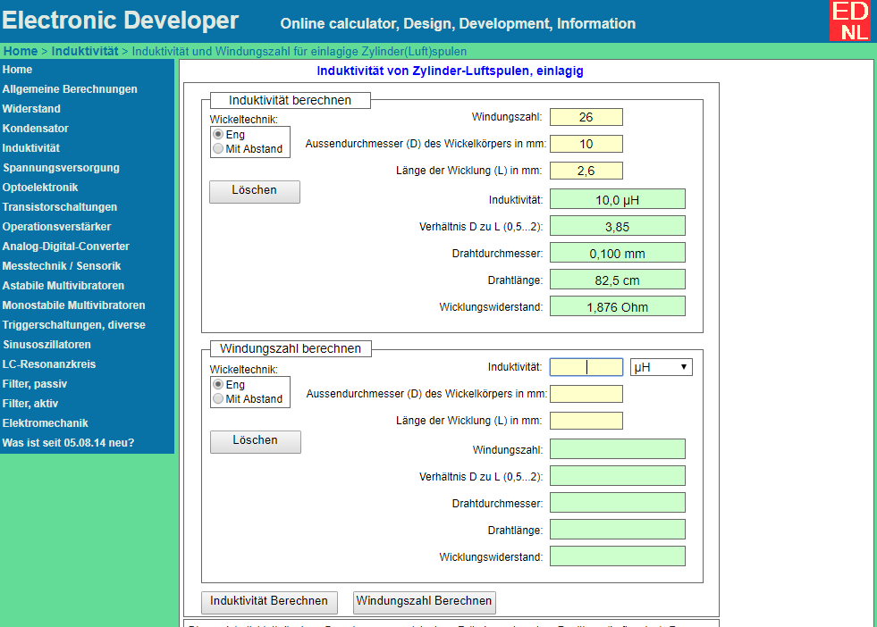
vodiczka wrote:L = 10 ?H, D = 10 mm, d = 0.1 mm http://www.pronine.ca/coilcal.htm 106 scrolls http://ekalk.eu/l_en.html 27 scrolls The following calculator indicates 26 turns: http://www.electronicdeveloper.de/InduktivitaetLuftEinl.aspx"Spore" is the percentage of the lower value?
Adamcyn wrote:This is a 4-fold difference, that is, passing the yen as if not both patterns with reality. It is worth doing both coils and measuring both cases with the tester.... L = 10 ?H, D = 10 mm, d = 0.1 mm http://www.pronine.ca/coilcal.htm 106 scrolls http://ekalk.eu/l_en.html 27 scrolls
DiZMar wrote:probably 26 turns; full compatibility of other parameters with the calculator Vodiczk i. http://www.electronicdeveloper.de/InduktivitaetLuftEinl.aspxIt is worth doing one and the other coil and measuring both cases with the tester.
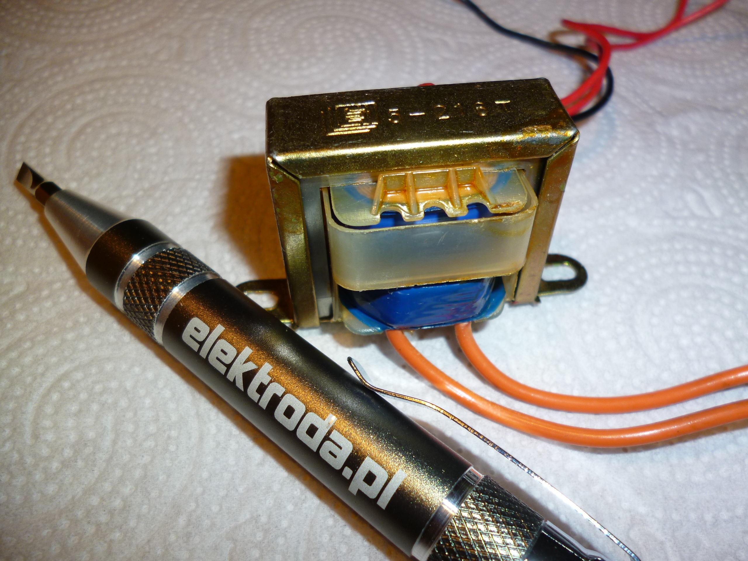
Adamcyn wrote:Well, he did not fully defend himself. If it is outside the range, it should "say" and do not indicate what "saliva into language will bring". And without the use of a metaphor, it should display a message that the result is out of range as normal meters or other "simple" devices measuring even weights. It should not be misleading.I have measured such a transformer: ... that is around 32 H. Check. The tester showed different values and had the right - 32 H is a value outside its range of 20 H. He defeated again.


TL;DR: LCR-T4 auto-tests 14 part types, draws only 12-15 mA per measurement, and “will be useful in every workshop” [Elektroda, TechEkspert, post #16556695] Accuracy stays within ±2 % for most resistors. Firmware flashing adds live-scan mode and Zener tests. Why it matters: you get multimeter-level insight from a €10 gadget.
• Supply: 9 V battery; 12-15 mA active, 20 nA sleep [Elektroda, 16556695] • R range: 0.1 Ω – 50 MΩ, C range: 25 pF – 100 000 µF, L range: 0.01 mH – 20 H [Elektroda, 16556695] • Typical accuracy: ±1 % R, ±3 % C, ±5 % L (user tests) [Elektroda, 16556695] • ESR read-out for electrolytics ≥1 µF [Elektroda, post #16556695] • Open-source firmware: AVR-based, 40 V boost for Zener mode [Elektroda, 16666684]