logo elektroda
logo elektroda
X
logo elektroda

Qiachip Smart Switch - BK7231N / CB2S - interior, programming

p.kaczmarek2 65136 288
ADVERTISEMENT
Treść została przetłumaczona polish » english Zobacz oryginalną wersję tematu
  • #271 20964767
    msatek
    Level 11  
    Hello participants.
    I have a smart BSD33 socket with the CB2S BK7231N+BL0937 module, I got it after testing with tuya-cloudcuter,
    I will describe in more detail + photos later. After desoldering the module, I have now uploaded the latest version of OBK and launched the module itself, but I have one problem with WiFi. The configuration allows you to program two APs and according to the description
    should connect to one of them. Unfortunately, it only connects to the first one, if it is missing it cannot connect to the second one. If I change the definitions, the AP will also connect to the one defined first. I`ve used Tasmota before and it works fine. Maybe some suggestions? Thank you in advance
  • ADVERTISEMENT
  • #272 20964802
    p.kaczmarek2
    Moderator Smart Home
    From what I remember, the second SSID field is simply not connected yet, it is the so-called placeholder , this should be handled in upcoming updates.
    Helpful post? Buy me a coffee.
  • ADVERTISEMENT
  • #273 20965971
    msatek
    Level 11  
    Thanks for the quick reply.
    compliments on the whole.
  • #274 21194907
    Tilator
    Level 10  
    Is there some kind of timing issue with DHT11? It seems to give a totally wrong values every now and then. DHT22 works just fine.

    Edit: This sounds now much like a loose connection.

    Edit2: Unfortunatelly still wrong values from DHT11. Not a single one from DHT22.

    I did try two different DHT11 sensors and even connected a pull up resistor to it, but the result is still same.
  • #275 21367346
    m0v0m
    Level 9  
    Hi all.
    I have a problem with flashing.
    I have a BK7231N/CB2S switch trying to read the firmware ends up with me getting a file with 2kB of just 0x00
    Any upload ends up failing.
    I tried to read from the beginning I powered the BK7231N on the board itself:
    ie Rx, Tx, to USB-TTL common GND, +5USB to IN AMS1117 - did not read,
    I decided not to play around - solder the CB2S module itself so 100% nothing would interfere and that didn't help :( .
    Trials were done: converter PL2303, CH340C - no difference,
    software: bk7231flasher_1.0.4 , hid_download_py-master , bk_writer1.60

    hid: tried in different ways, at different speeds.... nothing... simply hands are falling down.

    python uartprogram firmware3.bin -d com11 -b 57600 -r
    pause

    python uartprogram firmware33.bin -d com11 -b 9600 -r
    pause

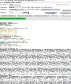
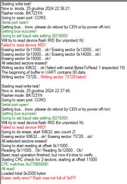
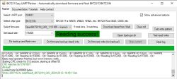
    log for bk7231flasher_1.0.4


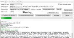
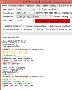
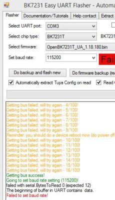
    Screenshot of UART flasher program for BK7231N. Screenshot of the BK7231 Easy UART Flasher program showing errors during flashing of the BK7231N module. .
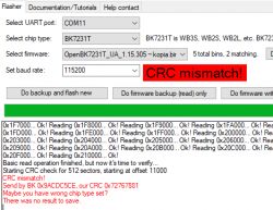
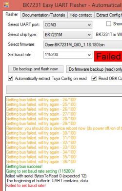
    Screenshot of logs from BK7231N flasher .


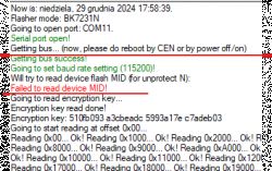
    in general, the beginning of Failed to read device MID is bizarre - such a text appears every time.

    Next steps:
    power supply from foreign 3.3V, common GND - same thing,

    OK, I'm thinking - maybe something's hit with this module.... I soldered another one from the same switch - same.
    I soldered the first one back on, start up, SmartLife - found it, works....

    Please help.

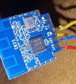
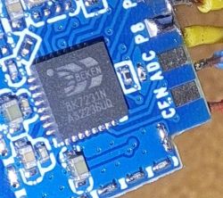
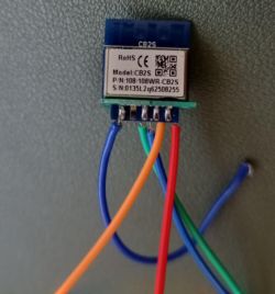
    Just pictures of the module:
    CB2S module with BK7231N chip and connected wires. .

    Close-up of an electronic module featuring a Beken BK7231N chip. .
  • #276 21367364
    p.kaczmarek2
    Moderator Smart Home
    Or is it a BK7231T in a CB2S housing? Try setting the BK7231T mode and then take a reading. I think I've seen a case like this before.
    Helpful post? Buy me a coffee.
  • #277 21367525
    m0v0m
    Level 9  
    >>21367364 .
    Thank you very much for your prompt reply. .
    ok. i'm already trying:
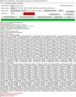
    Screenshot of Flasher program reading data from a microcontroller. .
    Screenshot of a flashing program showing a CRC mismatch error message during the BK7231T chip flashing process. .

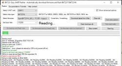
    But here, if I mark the chyp type as BK7231N - it reads:
    Screenshot of BK7231 Easy UART Flasher program with error message. .

    Screenshot of BK7231 Easy UART Flasher program with Reading success! message. .

    But I read as apparently Null Null Null Null Null....

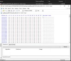
    HxD program window displaying the contents of a binary file with data saved as a string of zeros.
  • ADVERTISEMENT
  • #278 21367538
    p.kaczmarek2
    Moderator Smart Home
    Well, it might still be worth trying BK7231M mode....

    What does this CB2S look like? Does it have a metal screen, or without a screen? There is definitely a BK7231N inside?

    I ask because we have already had such cases where there was a CB2S module with, for example, a BK7231M inside.

    Added after 52 [seconds]: .

    PS: Do you have the latest flasher?
    Helpful post? Buy me a coffee.
  • #279 21367609
    m0v0m
    Level 9  
    >>21367538 .
    Ok now that's the option I'm going to try too.
    Here: above I already added a picture of the module itself: post #275 21367346 29 Dec 2024 15:09
    https://obrazki.elektroda.pl/1060023800_1735482435.png
    https://obrazki.elektroda.pl/2472121000_1735482401.png

    as you can see - no screen, on the chip itself it says BK7231N

    bk7231flasher_1.0.4 I used this.

    so I would like to remind you that I tried with HID too
    python uartprogram firmware333333333.bin -d com11 -b 57600 -r
    and on 9600 also poorly....

    I downloaded the latest version here: BK7231GUIFlashTool v5 https://github.com/openshwprojects/BK7231GUIFlashTool/releases

    Similar situation:
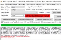
    Screen of the BK7231 Easy UART Flasher program displaying the message Only 0x00 bytes read. .


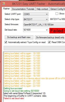
    Screenshot of BK7231N flasher application showing a device MID read error.


    I can still come back to note that when the program asks to reset CEN - it often continues reading without grounding CEN. Maybe this is the problem? But the situation doesn't change whether I use power from an external power supply or from USB. It works the same way.
  • #280 21367692
    p.kaczmarek2
    Moderator Smart Home
    Is this the first BK7231N you are flashing? Have previous ones been successfully programmed with your USB to UART converter?
    Helpful post? Buy me a coffee.
  • ADVERTISEMENT
  • #281 21367749
    Tilator
    Level 10  
    Just to be sure - rx is connected to tx and tx connected to rx?
  • #282 21367764
    m0v0m
    Level 9  
    p.kaczmarek2 wrote:
    the first BK7231N you flash? Were the previous ones successfully programmed with your converter
    .


    Yes with the BK7231 - this is the first experience.
    I have been struggling for almost a week now.... After evenings and without success.

    I tried the converter PL2303 , CH340C - no difference,
    two different, both work CH340C - 100% flashing ATMEGa
    PL2303 - I have also recently used for esp8266

    I don't read the device MID, and the read itself zeros itself....

    And please come back to note that when the program asks to reset CEN.
    Often the program continues reading without grounding CEN.
    Maybe this is the problem? But the situation does not change whether I use
    power supply from an external power supply or from USB. It works the same way.

    hid_download_py-master:
    Screenshot of a command prompt window showing a command and memory read results for BK7231N device. Screenshot of the results of firmware read and write operations. .


    Tilator wrote:
    To be sure - the rx is connected to the tx and the tx is connected to the rx?
    .


    Of course. I've checked a few times and tried to check the other way round just in case, but then I don't read anything at all.
  • #283 21368684
    Tilator
    Level 10  
    Is it possible the chinese have changed CB2S board somehow and there is a new component keeping some critical pin in wrong setting preventing flashing?

    I don't remember it straight away, but some pin should be kept low and some might need to keep high. It only takes one new resistor to prevent it. Or maybe one taken off.
  • #284 21368818
    p.kaczmarek2
    Moderator Smart Home
    @m0v0m maybe too long wires or bad USB to UART converter? There have already been reports of such problems on the forum.
    It works for me using this method: https://www.youtube.com/watch?v=YQdR7r6lXRY

    If you are from Poland, and I assume you are, you can also send me the modules to upload the OBK.

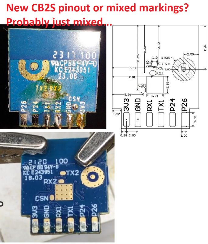
    And I have another idea - did you connect according to:
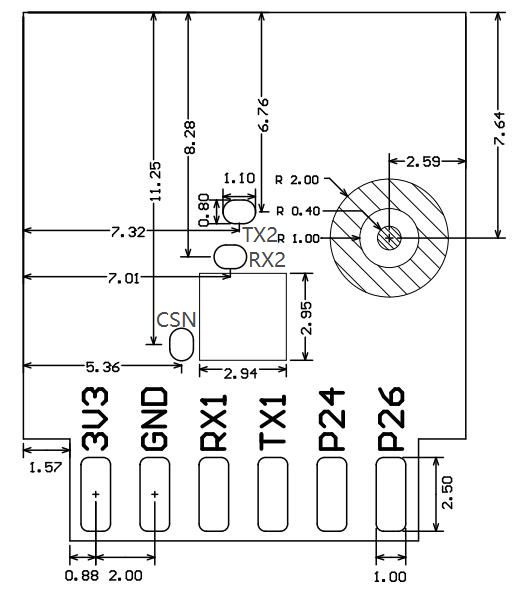
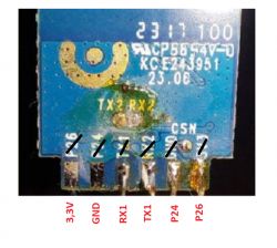
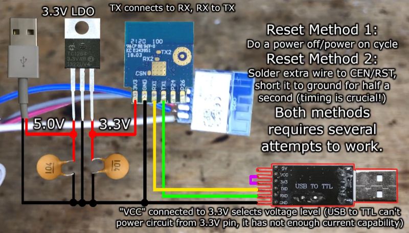
    Diagram showing the pin layout on a board with labels: 3V3, GND, RX1, TX1, P24, P26, TX2, RX2, CSN. .
    There is a CB2S series on the market with incorrect markings! This can be misleading! Always connect according to the documentation! .
    Yes looking at the photo from the forum:
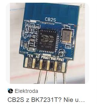
    CB2S module with BK7231T chip and connectors. .
    ... I guess that's what you have?
    Helpful post? Buy me a coffee.
  • #285 21372428
    m0v0m
    Level 9  
    p.kaczmarek2 wrote:
    If you are from Poland, and I assume you are, you can also send me the modules to upload the OBK.


    Thanks, we can try that way, at least to make sure everything is ok with the module.
    I've already written to figure out the logistics somehow.

    Tilator wrote:
    I don't remember this right away, but some pins should be kept low and some may need to be kept high.
    .

    Exactly, maybe something like this is required by these modules....
  • #286 21372442
    p.kaczmarek2
    Moderator Smart Home
    Also check what I wrote about the location of the RX1/TX1 pads. Show a photo from the side of those pads.
    Helpful post? Buy me a coffee.
  • #287 21372605
    m0v0m
    Level 9  
    Welcome everyone to the New Year :) .

    This is what the module looks like (sorry for the uncleared top):
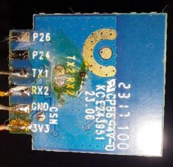
    Close-up of an electronic module with visible pins and labels. .
    Uncleaned electronic module with visible connectors and labeled CB2S. .

    Exactly:
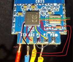
    DESCRIPTION +3.3V in truth is P24
    DESCRIPTION of GND in truth is P26
    .
    .


    Image of an electronic module with wires labeled in different colors, indicating connections such as +3.3V, GND, RX, and TX. .


    Rx Tx as seen in the pictures

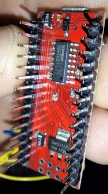
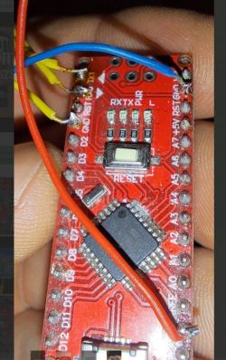
    And the next iteration - trying to use the programmer from the Arduino Nano:

    Close-up of an electronic module in hand. .
    Close-up of an Arduino Nano module with attached wires. .

    I trimmed the sticks for the Atmega.
    But that didn't work either. :(
  • #288 21372640
    p.kaczmarek2
    Moderator Smart Home
    So it's not as I wrote? Plus those RX2s twice...
    Compare for yourself:
    Close-up of a CB2S board with TX2 and RX2 labels and a pinout diagram. .
    See this topic, identical situation:
    Flashing OpenBK on CB2S using BK7231Flasher - connection problems .
    Read the linked material and connect the programmer according to the correct leads.
    Helpful post? Buy me a coffee.
  • #289 21373187
    m0v0m
    Level 9  
    Thank you.
    You were 100% right I made a mistake - I didn't check the pins.


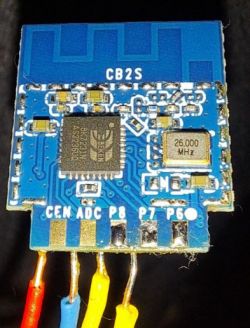
    Close-up of a circuit board with pins labeled 3.3V, GND, RX1, TX1, P24, P26. .

    After proper connection frimware uploaded flawlessly.

Topic summary

The discussion centers on the teardown and custom firmware programming of the Qiachip Smart Switch featuring the CB2S module based on the BK7231N chip, distinct from the BK7231T. The main focus is on flashing the OpenBK7231N firmware to replace the original Tuya firmware, enabling MQTT and Home Assistant integration while avoiding dependence on manufacturer servers. Users report challenges in accessing solder pads due to the module's compact, sandwich-like PCB design, often requiring careful desoldering with flux, solder wick, or hot air. Programming requires connecting 3.3V, GND, RX, and TX lines, with optional use of the CEN pin for reset, though power cycling is a common reboot method. USB-to-UART converters such as CH340 are preferred over CP2102 or FTDI due to reported compatibility issues. Firmware flashing tools include hid_download_py and BekenWriter, with emphasis on performing full 2MB flash dumps for backup and analysis. Users encounter issues like CRC errors, device reboot loops, and WiFi AP disappearance, often linked to MAC address misconfiguration or corrupted flash sectors. Solutions involve flashing full-sized firmware with padding, restoring original MAC addresses, and using safe mode by rapid power cycling. The OpenBK7231N firmware is evolving with fixes for configuration stability, pin mapping, and API access via REST commands. Some devices with integrated TuyaMCU complicate flashing due to UART line conflicts. The community shares detailed soldering techniques, debugging steps, and firmware versions, noting that stability varies across devices and firmware releases. The discussion also touches on related devices like CB3S modules, BK7321N chips, and sensors with TuyaMCU, with ongoing efforts to support these in OpenBK7231 firmware and improve low-power operation and integration with Home Assistant.
Summary generated by the language model.
ADVERTISEMENT