Elektroda.com
Elektroda.com
X

Tasmota replacement for BL602, programming, pairing with Home Assistant, now with OTA working!

p.kaczmarek2 49599 359
This content has been translated flag-pl » flag-en View the original version here.
  • #121
    winux22
    Level 2  
    Hello i flashed OpenBL602_1.12.8.bin on a Sonoff MiniR3 as described above.
    Flash was successful but the device does not boot after opening the boot-3,3V connection and power cycling.
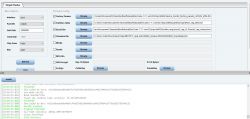
    When i try to log in DevCube i get an error. Do i need a different Partition Table or Params?
    The Chip is a BL602L20.
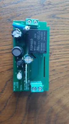
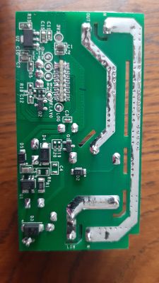
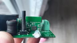
    Some Pics and flash logs are in the attachment.
    Cheers Winux
  • #122
    winux22
    Level 2  
    Sorry totally my bad :D
    I had the same problem as bartek666666. I kinda missed that page of the thread.
    The problem was i downloaded the devcube programmer from the buffalos website. It's a different version.
    The one in your repo worked first try. I thought about deleting the post above, but i will leave it there for the pictures. Maybe it helps someone.
    Tasmota replacement for BL602, programming, pairing with Home Assistant, now with OTA working!

    Added after 3 [hours] 30 [minutes]:

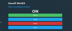
    Here are some more infos for the Sonoff MiniR3
    Pins:
    Wifi LED: 1
    Button: 5
    Relais: 22

    I would have sent a pull request but i don't have my credentintials with me at the moment.
    So for the sake of completeness feel free to add the following to the code:
    /src/new_builtin_devices.c
    // DeviceName: Sonoff MiniR3
    // ShortDeviceName: minir3
    // https://sonoff.tech/product/minir3
    void Setup_Device_Sonoff_MiniR3() {
    	CFG_ClearPins();
    
    	PIN_SetPinRoleForPinIndex(1, IOR_LED_WIFI);
    	PIN_SetPinChannelForPinIndex(1, 0);
    	
    	PIN_SetPinRoleForPinIndex(5, IOR_Button);
    	PIN_SetPinChannelForPinIndex(5, 1);
    
    	PIN_SetPinRoleForPinIndex(22, IOR_Relay);
    	PIN_SetPinChannelForPinIndex(22, 1);
    
    	CFG_Save_SetupTimer();
    }

    /src/new_pins.h
    void Setup_Device_Sonoff_MiniR3();

    /src/httpserver/http_fns.c
    { Setup_Device_Sonoff_MiniR3, "Sonoff MiniR3"},

    Generate Openhab Things Entry
    // Sonoff MiniR3
    Thing topic minir3_1 "Sonoff MiniR3 1" {
        Channels:
            Type switch : PowerSwitch  [stateTopic="minir3/1/get", commandTopic="minir3/1/set", on="1", off="0"]
    }
    Tasmota replacement for BL602, programming, pairing with Home Assistant, now with OTA working!
    That's it. Thx, it's working quite nicely.
    Tasmota replacement for BL602, programming, pairing with Home Assistant, now with OTA working!
  • #123
    p.kaczmarek2
    Moderator Smart Home
    Thanks, I will look into it when I have more time, same goes for LED driver update.

    I have BL602 bulb at hand, the one with I2C LED controller (SM2135), I will also try to get it running. Or it should already run, as the SM2135 driver is only using digital pins IO and OBK has it already working and tested for BK7231
  • #124
    theugster
    Level 1  
    Howdy!

    First off, thanks so much for your work on this project! I accidentally bought a pack of Sonoff S40 smart plugs with power monitoring and figured I'd try to cut my losses and see if I could harvest the switch boards from these. Took *way* too long to get the correct wiring layout (the board has two sets of rx/tx pads for some reason) but I was eventually able to flash the latest firmware. Unfortunately it appears to be in a bootloop now, and never gets to a point where it's broadcasting a WiFi AP.

    The error(s) it appears to throw in the console are:
    [0m: bl_romfs.c: 146] romfs magic is NOT correct

    and
    [ 39][INFO : hal_gpio.c: 115] [gpio1] status = disable
    [ 39][ERROR
    : hal_gpio.c: 216] gpio1: unvalid GPIO config
    [ 40][ERROR
    : hal_gpio.c: 130] gpio2: unvalid GPIO config button
    [ 40][ERROR
    : hal_gpio.c: 216] gpio2: unvalid GPIO config
    [ 41][INFO : hal_gpio.c: 106] gpio3 NOT found


    I've attached some logs and a screenshot of the Dev Cube app. Happy to provide some pictures of the board itself as well, this seems to be a fairly new one.

    Thanks again!
  • #125
    p.kaczmarek2
    Moderator Smart Home
    That's a strange error, I have never seen it before.

    At first, can you try downloading compiled GPIO demo from their SDK, here:
    https://www.elektroda.com/rtvforum/viewtopic.php?p=20117857#20117857
    and checking if at least it works on your device? It has an UART console to control pins. Try commands from the first post from this topic, gpio-func, gpio-set, etc...

    Also, good job with finding the wiring. Can you please photos of boards and the wiring to help other users with flashing Sonoff S40?
  • #126
    winux22
    Level 2  
    I sent a pull request on github for the Sonoff MiniR3 from above.

    I compiled the code and realised i'm not able to update via wifi ^^, so i had to get the device out of the garden and solder again to update the firmware. An update solution for the BL602 devices would be real nice.

    Things that could be improved:

    - Possibility to update the BL602 Devices via wifi.

    - Quick configs should also store device name as well as device short name. Device short name could be also used for the Hostname.

    - Timers
    As seen in Tasmota:
    https://github.com/arendst/Tasmota/blob/development/tasmota/tasmota_xdrv_driver/xdrv_09_timers.ino
    Tasmota replacement for BL602, programming, pairing with Home Assistant, now with OTA working!
    It's neat to have them running on the device, especially for pumps or automated lights.
    Another neat idea would be an override for the timer via mqtt if available.
    Let's say the device turns a pump on every day to water plants or grass via local timer on the device. The smarthome software detects rain for a given day and sets an mqtt topic to 0. The Timer checks that topic as soon as a trigger happens and ignores watering for that day.

    That's all i'm missing so far. The Update solution would be top prio.
    Have a great day.
  • #127
    blakadder
    Level 6  
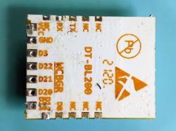
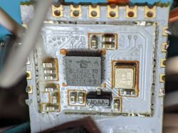
    I got a CozyLife bulb with a DT-BL200 slightly different from the one p.kaczmarek2 posted. Mine doesn't have anything written on the RF shield and the code on the back is `2120`.

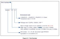
    Removing the shield reveals a BL602L20 chip. According to the datasheet L is for "light" chips compared to the usual C/E which tracks.

    Tasmota replacement for BL602, programming, pairing with Home Assistant, now with OTA working!

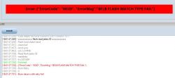
    I wasn't able to flash it using the DevCube flashing tool in the Open602 repo. It errors out after trying to read flash vendor ID.

    Tasmota replacement for BL602, programming, pairing with Home Assistant, now with OTA working!

    Flash was complete using the latest official BLDevCube 1.7.5. but OpenBeken firmware does not boot.

    It seems to be related to https://gist.github.com/lupyuen/2cb2034a436dc75acc1aeb63ea3b9aa1

    Tasmota replacement for BL602, programming, pairing with Home Assistant, now with OTA working! Tasmota replacement for BL602, programming, pairing with Home Assistant, now with OTA working!
  • #128
    mgerald21
    Level 2  
    Hello p.kaczmarek2,

    great work so far.

    I've flashed an RGBW LED-strip controller with the latest OpenBL602 1.12.39.bin and the first boot did work ok. I could connect to the Wifi AP OpenBL602_Xxxxx, got IP address 192.168.169.2 and could connect to the Config Page. After I setup the SSID, password, MQTT, etc. the device reboots but seems to be in an endless reboot loop now.

    I did try sdk_app_gpio.bin which works fine, and I did flash the bl602_demo_wifi and right after the start of the WIFI the device reboots.
    Did I overwrite some factory default; e.g. calibration settings?

    Starting bl602 now....
    Booting BL602 Chip...
    ██████╗ ██╗      ██████╗  ██████╗ ██████╗
    ██╔══██╗██║     ██╔════╝ ██╔═████╗╚════██╗
    ██████╔╝██║     ███████╗ ██║██╔██║ █████╔╝
    ██╔══██╗██║     ██╔═══██╗████╔╝██║██╔═══╝
    ██████╔╝███████╗╚██████╔╝╚██████╔╝███████╗
    ╚═════╝ ╚══════╝ ╚═════╝  ╚═════╝ ╚══════╝
    
    
    ------------------------------------------------------------
    RISC-V Core Feature:RV32-ACFIMX
    Build Version: release_bl_iot_sdk_1.6.11-1-g66bb28da-dirty
    PHY   Version: a0_final-44-geb7fadd
    RF    Version: f76e39a
    Build Date: Aug 19 2022
    Build Time: 19:22:24
    ------------------------------------------------------------
    Heap 133786@0x42020d66, 2144@0x4204b7a0
    Boot2 consumed 62ms
    
    blog init set power on level 2, 2, 2.
    [IRQ] Clearing and Disable all the pending IRQ...
    ------------------TRNG TEST---------------------------------
    **********TRNG TEST rand[307be52d]**************
    **********TRNG TEST rand[127cb7ce]**************
    ------------------------------------------------------------
    [         0][INFO  : hal_boot2.c: 276] [HAL] [BOOT2] Active Partition[0] consumed 596 Bytes
    ======= PtTable_Config @0x4200d9cc=======
    magicCode 0x54504642; version 0x0000; entryCnt 7; age 0; crc32 0x12DF9A26
    idx  type device activeIndex     name   Address[0]  Address[1]  Length[0]   Length[1]   age
    [00]  00     0         0            FW  0x00010000  0x000d8000  0x000c8000  0x00088000  0
    [01]  02     0         0           mfg  0x00160000  0x00000000  0x00032000  0x00000000  0
    [02]  03     0         0         media  0x00192000  0x00000000  0x00057000  0x00000000  0
    [03]  04     0         0           PSM  0x001e9000  0x00000000  0x00008000  0x00000000  0
    [04]  05     0         0           KEY  0x001f1000  0x00000000  0x00002000  0x00000000  0
    [05]  06     0         0          DATA  0x001f3000  0x00000000  0x00005000  0x00000000  0
    [06]  07     0         0       factory  0x001f8000  0x00000000  0x00007000  0x00000000  0
    [         0][INFO  : bl_flash.c:  96] ======= FlashCfg magiccode @0x42049c18, code 0x47464346 =======
    [         0][INFO  : bl_flash.c:  97] mid               0xEF
    [         0][INFO  : bl_flash.c:  98] clkDelay  0x1
    [         0][INFO  : bl_flash.c:  99] clkInvert         0x1
    [         0][INFO  : bl_flash.c: 100] sector size       4KBytes
    [         0][INFO  : bl_flash.c: 101] page size 256Bytes
    
    ...
    snip
    ...
    0th channel,vco_idac_cw=10
    1th channel,vco_idac_cw=10
    2th channel,vco_idac_cw=9
    3th channel,vco_idac_cw=10
    4th channel,vco_idac_cw=10
    5th channel,vco_idac_cw=9
    6th channel,vco_idac_cw=9
    7th channel,vco_idac_cw=9
    8th channel,vco_idac_cw=9
    9th channel,vco_idac_cw=9
    10th channel,vco_idac_cw=9
    11th channel,vco_idac_cw=9
    12th channel,vco_idac_cw=9
    13th channel,vco_idac_cw=9
    14th channel,vco_idac_cw=9
    15th channel,vco_idac_cw=9
    16th channel,vco_idac_cw=9
    17th channel,vco_idac_cw=9
    18th channel,vco_idac_cw=8
    19th channel,vco_idac_cw=8
    20th channel,vco_idac_cw=8
    LO locked 9 138
    rosdac_i_gc3=27
    rosdac_i_gc2=27
    rosdac_i_gc1=27
    rosdac_i_gc0=27
    rosdac_q_gc3=30
    rosdac_q_gc2=30
    rosdac_q_gc1=30
    rosdac_q_gc0=30
    rbb_cap1_fc_i=25,rbb_cap2_fc_i=25,rbb_cap1_fc_q=25,rbb_cap2_fc_q=25
    new rbb_cap1_fc_i=49,rbb_cap2_fc_i=49,rbb_cap1_fc_q=49,rbb_cap2_fc_q=49
    ▒Starting bl602 now....
    Booting BL602 Chip...
    ██████╗ ██╗      ██████╗  ██████╗ ██████╗
    ██╔══██╗██║     ██╔════╝ ██╔═████╗╚════██╗
    ██████╔╝██║     ███████╗ ██║██╔██║ █████╔╝
    ██╔══██╗██║     ██╔═══██╗████╔╝██║██╔═══╝
    ██████╔╝███████╗╚██████╔╝╚██████╔╝███████╗
    ╚═════╝ ╚══════╝ ╚═════╝  ╚═════╝ ╚══════╝
    
  • #129
    Maniac2002
    Level 5  
    Hallo,

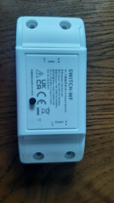
    I habe a Switch-wf which contains a bl602.
    Have Someone flashed this device and can give me help how to Do it? What do i need for firmware and other files.

    Best regards
    Maniac 2002
  • #130
    blakadder
    Level 6  
    Maniac2002 wrote:
    Hallo,

    I habe a Switch-wf which contains a bl602.
    Have Someone flashed this device and can give me help how to Do it? What do i need for firmware and other files.

    Best regards
    Maniac 2002


    It helps to post images of the device and its label/model number or at least a link to where you purchased it.
  • #131
    p.kaczmarek2
    Moderator Smart Home
    This is a very important information @blakadder , thank you for providing that. It seems that they really have broken compatibility with older flashes, this is not good. It looks like I will really have to get the new BL602 SDK and keep both SDKs alive just to support the newly-created two families of BL602 chips (old and new ones). It could be also possible to alter existing SDK to generate two flash formats, but I am not sure is it viable when it comes to time cost.

    Maybe at least this new SDK has a better OTA (from what I've seen, yes, it was added later in time)

    @Maniac2002 we will help you step by step but you need to provide some more information, photos, etc

    @mgerald21 even the WiFi SDK demo crashes for you?
  • #132
    mgerald21
    Level 2  
    Quote:
    even the WiFi SDK demo crashes for you?

    Well, the WiFi demo did start but crashed right after doing something with WiFi.

    But in the end it was my fault because the chip was powered by the USB adapter's 3v3 and obviously that wasn't enough and the system crashed. After providing a 12V power supply all was Ok.
  • #133
    p.kaczmarek2
    Moderator Smart Home
    mgerald21 wrote:

    But in the end it was my fault because the chip was powered by the USB adapter's 3v3 and obviously that wasn't enough .

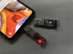
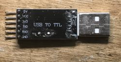
    did you use this USB to UART dongle?
    Tasmota replacement for BL602, programming, pairing with Home Assistant, now with OTA working!
    as far as I know, the 3.3V and 5V pins are just used to select VDD levels by puting a jumper between them.

    Still, the WiFi crash due to low power is also known to me. I even had device with a faulty electrolytic capacitor which started randomly resetting because capacitor gone bad and power supply was not providing enough stable voltage/current.
    See (not yet translated):
    https://www.elektroda.pl/rtvforum/topic3898805.html
  • #134
    mgerald21
    Level 2  
    Yes, these USB dongles seems to have an internal 3v3 LDO which can provide enough power for flashing but not for regular WiFi operations.
  • #135
    p.kaczmarek2
    Moderator Smart Home
    It's a classic trap for young players, this is why I have soldered extra wire directly to 5V pin on that USB to UART dongles, and use it along with TC1264 3.3V LDO or the on-board LDO of smart device pcb if possible
  • #136
    blakadder
    Level 6  
    Some adapters sometimes do not even have enough power for flashing, depending on the chip/ module you're flashing. In Tasmota community we always recommend the "golden CH340G" which always works.

    If you're looking for a bit more serious tool get an ESP8266 burner board (https://s.click.aliexpress.com/e/_DeodsyT *affiliate link)
  • #137
    droege
    Level 10  
    Hi again,
    well, an OTA for BL602 would be great. Also for the "old" flash chip/sdk.
    But beyond that, can I request again the following (then OTA wouldn't be so urgent anymore):
    MQTT reporting:
    reporting a calculated dimmer value after setting a new RGB value and therefore overwriting a dimmer value with RGB settings;
    beyond that, reporting final color together with dimmer, whenever a value (RGB/dimmer/Hue/Sat) is changed.

    Thanks,
    best.
  • #138
    Maniac2002
    Level 5  
    Hello,
    so here comes the information.
    It is a Switch-WF.
    Tasmota replacement for BL602, programming, pairing with Home Assistant, now with OTA working! Tasmota replacement for BL602, programming, pairing with Home Assistant, now with OTA working! Tasmota replacement for BL602, programming, pairing with Home Assistant, now with OTA working! Tasmota replacement for BL602, programming, pairing with Home Assistant, now with OTA working!

    It has a Bl602L20.

    Please can you give me a step by step manual
    I have a USB to UART Dongle and i have already soldered teh cables to the PCB (RX,TX, GND and 3.3V)
    Ma Questionss are:

    Which flashing Tool do i nedd?
    Which firmwarefiles do i need.
    What do i need to do to flasch the "tasmota replacement firmware" to the device?

    Thanks in advance and best regards
    Maniac2002
  • #139
    blakadder
    Level 6  
    For now you have to piece together information from this thread but step by step instructions are being worked on.
  • #140
    p.kaczmarek2
    Moderator Smart Home
    Maniac2002 wrote:

    I have a USB to UART Dongle and i have already soldered teh cables to the PCB (RX,TX, GND and 3.3V)

    what about the BOOT pin? Do you also have a pad for that?

    If not sure, you can try looking closely at the module and following the PCB tracks.
  • #141
    Maniac2002
    Level 5  
    p.kaczmarek2 wrote:
    Maniac2002 wrote:

    I have a USB to UART Dongle and i have already soldered teh cables to the PCB (RX,TX, GND and 3.3V)

    what about the BOOT pin? Do you also have a pad for that?

    If not sure, you can try looking closely at the module and following the PCB tracks.

    The boot pin ist the button on the PCB

    Hinzugefügt nach 1 [Stunden] 30 [Minuten]:

    Hi,

    Now i have found the "Beken Writer 1,60" and the Firmware File "OpenBL602_1.12.41.bin".

    Is this 2 Files all that i need to flash the new Firmware to my Switch-WF or du i need something else?

    Thanks in andvance and best regards
    Maniac2002
  • #142
    p.kaczmarek2
    Moderator Smart Home
    Hey, bkWriter is for BK chips, BK7231T, BK7231N, etc. You are trying to program BL602.

    For BL602, you should use blDevCube, as stated in the first post in this topic.

    How do you know that the BOOT pin is the button? Have you checked the PCB tracks?
  • #143
    droege
    Level 10  
    droege wrote:
    Hi again,
    well, an OTA for BL602 would be great. Also for the "old" flash chip/sdk.
    But beyond that, can I request again the following (then OTA wouldn't be so urgent anymore):
    MQTT reporting:
    reporting a calculated dimmer value after setting a new RGB value and therefore overwriting a dimmer value with RGB settings;
    beyond that, reporting final color together with dimmer, whenever a value (RGB/dimmer/Hue/Sat) is changed.

    Thanks,
    best.


    Hey again,
    some testing, with the new firmware:
    when using flag 3: report MQTT final color, the devices crashes after 2-3 minutes changing colors every 20-30 seconds. This is not stable.
    whan turning off MQTT reporting the device stays stable. But that's not desired.
    Can you fix it?
    Best.
  • #144
    p.kaczmarek2
    Moderator Smart Home
    Thank you for reporting. It seems you are still experiencing the same issue related to MQTT crashing when doing a lot of publish calls. I tried to mitigate it but it happens if you have lots of flags enabled.

    Are you saying that the new versions are more prone to this crash? It may be related to that change made by Indu Prakash:
    https://github.com/openshwprojects/OpenBK7231T_App/commit/3c1defb06007c75c3f55118b7dd76678890825cd

    The final solution is yet to be determined.
  • #145
    zaedow
    Level 1  
    roli1 wrote:
    I just flashed succsessfully a BL602 as you described.

    Tasmota replacement for BL602, programming, pairing with Home Assistant, now with OTA working!
    A Accsess Point is shown "OpenBL602_94F30D07" and i can connect to it.

    I just cannot connect to 192.168.4.1

    What i'm doing wrong
    Thanks Roli


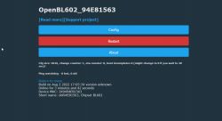
    If you have successfully connected your pc to the BL602's hotspot, run ipconfig on your laptop to see what the IP is you got on your Wireless LAN adapter Wi-Fi. In my case the default gateway was something like 192.168.1xx.1 then take that address.
  • #146
    bxwen19
    Level 5  
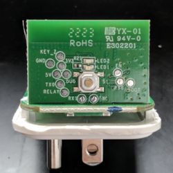
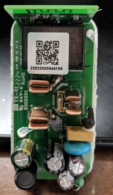
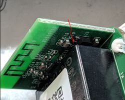
    Got one S40 openned. Please let me know what I should do next. There are Tx0, Rx0, Tx1, Rx1. Tasmota replacement for BL602, programming, pairing with Home Assistant, now with OTA working! Tasmota replacement for BL602, programming, pairing with Home Assistant, now with OTA working!
  • #147
    p.kaczmarek2
    Moderator Smart Home
    So that's a BL602 device? Well, you need 3 signals - BOOT (visible on photo), RX1 and TX1 (visible on photo).

    Also you need to power it, and NEVER power it from mains while programming - this might even destroy your PC. Maybe you can power it from 5V, 5V and GND pads are also visible on photo.

    Where does the 5V pad go? To AMS1117?
  • #148
    bxwen19
    Level 5  
    To my surprise, 5V is connected to pin 2 of U3, which looks like an ams1117.

    Tasmota replacement for BL602, programming, pairing with Home Assistant, now with OTA working!
  • #149
    p.kaczmarek2
    Moderator Smart Home
    Then you don't need an external 3.3V LDO regulator. You can use that AMS1117. So, you need to solder 5V, GND, TX, RX and boot. Please also read the instructions in the first post.
  • #150
    bxwen19
    Level 5  
    Isn't pin 2 the output of AMS1117? I can supply ether 5V or 3.3V. I wonder if I should use the 3.3V pad.