logo elektroda
logo elektroda
X
logo elektroda

Tasmota replacement for BL602, programming, pairing with Home Assistant, now with OTA working!

p.kaczmarek2 119136 485
ADVERTISEMENT
Treść została przetłumaczona polish » english Zobacz oryginalną wersję tematu
  • #181 20261004
    GabrielGrabowski
    Level 6  
    yipe wrote:
    @GabrielGrabowski Are you uploading 1.4.8 or another version? I had a similar experience when I uploaded 1.8.0
    I tried different versions, unfortunately each of them was the same. I still haven`t gotten over it. Does anyone have an idea what the problem might be?
  • ADVERTISEMENT
  • #182 20261071
    francwalter
    Level 7  
    p.kaczmarek2 wrote:
    Hello @Maniac2002 . I will try to help you here. You need to find BOOT pin, which is, unless I'm much mistaken, the GPIO8.
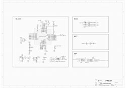
    Please refer to this schematic: (this is another board)
    Tasmota replacement for BL602, programming, pairing with Home Assistant, now with OTA working!
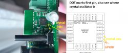
    I have composed an image for you. The dot marks the first pin. See where GPIO8 is:
    Tasmota replacement for BL602, programming, pairing with Home Assistant, now with OTA working!
    Now, my question is, where does the via goes with GPIO8? Can you look at the other side of the board? Where is this PCB track connected? I can't clearly see it on your photos...

    Maybe you can check with multimeter where does GPIO8 goes?

    Hallo @p.kaczmarek2 I think I could take it from here, as @Maniac2002 didnt post anymore about the Boot-Pin - hopefully he was not electrocuted by opening this Switch-WF ;-)

    I had bought the same switches (4x ebay nr. e.g.: 314044964133), I had bought them in the thought they were sonoff (Tasmota flashable). In Discord the very helpful "sfromis" pointed me to your work.
    Now I found your great entry how to flash them BL602 chips :) Thank you already for the big and thorough work!!!
    I will look (and measure) where the GPIO8 goes to on the board. I have to open it again, my photos are not good enough.
    Hier some pics (after I soldered the LED out to get sight on to the chip daughter-board):

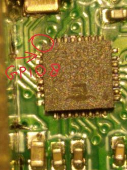
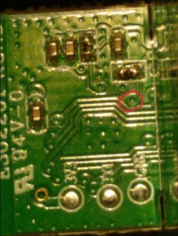
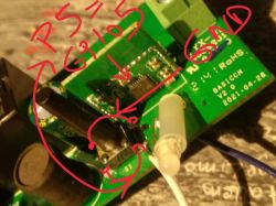
    As you say, the GPIO8 is near the Quartz at the border. I made a red circle around a point, just to show its position on the other side:
    Tasmota replacement for BL602, programming, pairing with Home Assistant, now with OTA working!
    Here the position from the other side (its is not the GPIO8, I think, it is just a spot, which is on both sides, which helps me to find the position, but anyway, it didnt help, I used my multimeter and try and error):
    Tasmota replacement for BL602, programming, pairing with Home Assistant, now with OTA working!
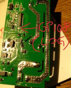
    and I measured it (with difficulties, because so small contact) to the soldering spot where I read "LOG":
    Tasmota replacement for BL602, programming, pairing with Home Assistant, now with OTA working!
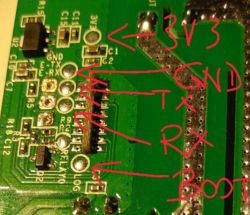
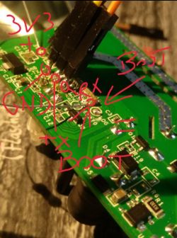
    So the GPIO8 (Boot) Pin is, as I think, just the LOG soldering-spot on the backside, so these should be the 5 interesting spots:
    Tasmota replacement for BL602, programming, pairing with Home Assistant, now with OTA working!

    Is this realistic or could I be totally wrong?
    The GND, RX, TX marks on the backside of the board are not directly beside the spots, but on a space where it could be printed, so I guess they are in order of the soldering-spots and right, right?
    Thank in advance.
    Please give me green light to flashem :)

    Edit: without an answer I will try to flash anyway ;)

    Added after 8 [hours] 32 [minutes]:

    But when I would try to flash, the next huge problem arises:
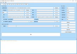
    On your step " For the user - loading the firmware ... 3. In BLDevCube.exe select files in turn: " you have a screenshot of an older version of the Bouffalo Lab Dev Cube, version 1.4.8 but I found only the download for v1.8 and this tool looks totally different.
    Here I can enter in "partition table" the file "partition_cfg_2M.toml" from the downloaded zip (in bl602\partition\), which I think is the same as you had.
    Furhter I put the new firmware "OpenBL602_1.14.101.bin" in the "firmware" input.
    "Factory params" in your screenshot is in mine "dts" I guess and here I put "bl_factory_params_IoTKitA_40M.dts" from folder "device_tree".
    And "Boot2 Bin" could be "boot2" here I put "BLDevCube-v1.8.0/chips/bl602/builtin_imgs/boot2_isp_bl602_v6.4_rc6/boot2_isp_release.bin"

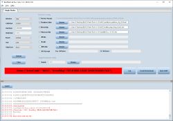
    It looks like this now:

    Tasmota replacement for BL602, programming, pairing with Home Assistant, now with OTA working!
    Are these files right?
    I have a warning in the log: Warning: This v1 partition table is deprecated

    I wonder why you did not mention this at all in your howto, it is not clear to me.
    All the other settings in the tool I didnt change, I hope they fit.
    Could you help?
    Thank!
  • #183 20262199
    omelchuk890
    Level 11  
    francwalter wrote:
    On your step " For the user - loading the firmware ... 3. In BLDevCube.exe select files in turn: " you have a screenshot of an older version of the Bouffalo Lab Dev Cube, version 1.4.8 but I found only the download for v1.8 and this tool looks totally different. Here I can enter in "partition table" the file "partition_cfg_2M.toml" from the downloaded zip (in bl602\partition\), which I think is the same as you had.

    https://www.elektroda.com/rtvforum/topic3889041-90.html#20117857
    attachments to the post, It should be moved to the first post...
  • #184 20262610
    francwalter
    Level 7  
    Thank, used 1.4.8 then, and the actual firmware OpenBL602_1.14.101.bin.
    But it failed:
    Tasmota replacement for BL602, programming, pairing with Home Assistant, now with OTA working!
    BFLB LOAD HELP BIN FAIL
    So I dont know what that means, either my Boot Pin is wrong or anything other is not working.
    Cannot continue like this, I even dont know how to check which part is not working.

    It was an experiment.
  • ADVERTISEMENT
  • #185 20262640
    omelchuk890
    Level 11  
    @francwalter reduce the speed from 2000000 to 500000, the speed of the uart, experiment, my recording also does not work at such a high speed as 2M
  • #186 20265202
    p.kaczmarek2
    Moderator Smart Home
    BL602 platform-specific SDK has been updated. Multiple new fixes introduced. The MQTT problem (crash) reported by @droege has been fixed. The platform should be more stable now

    Futhermore, I have enabled most of the OBK drivers on BL602, including the LED ones (SM2135 and friends).
    Helpful post? Buy me a coffee.
  • #187 20268666
    p.kaczmarek2
    Moderator Smart Home
    @francwalter thank you for switch analysis. As said earlier in this topic, you should use the same version of flashing tool that is in the FIRST post of this topic, not a different one.
    You can find it as attachment somewhere in this topic, you can also find it here (but you need to download whole dir):
    https://github.com/openshwprojects/OpenBL602/tree/master/tools/flash_tool
    BLDevCube.exe
    EDIT: If it still fails in the correct version, can you check:
    - are you correctly entering the bootloader mode? How your connection looks like?
    - Maybe you have swapped RX and TX? Try swapping them
    - do you have any other software that may use the UART COM port, like Cura, or RealTerm open? Please close it, COM port should be free
    - do you have each setting set as in my first post, check the screenshots
    Helpful post? Buy me a coffee.
  • ADVERTISEMENT
  • #188 20268941
    francwalter
    Level 7  
    Thank you for the answer!
    p.kaczmarek2 wrote:
    ... you should use the same version of flashing tool that is in this post, not an earlier one...
    Do you mean newer one?
    The 1.4.8 is the one in your first post, omelchuk890 gave me the link for the 1.4.8, after I didn't know where to put what in the 1.8 (from Buffalo I could download the 1.8, a newer one). I tried to flash only with 1.4.8 (see post #184).
    This wrong?
    p.kaczmarek2 wrote:
    ...are you correctly entering the bootloader mode?...

    How can I check that ?
    I think this is my crucial problem.
    The boot pin, I am not sure about it.
    EDIT: but now I have a mini soldering tool (runs with 12V) and I am ready to try again, even with another of my 4 Switch-WF devices :)
  • #189 20269065
    p.kaczmarek2
    Moderator Smart Home
    The tool from first post is correct. I have edited my post for clarity.

    You are supposed to connect BOOT (GPIO8) to ground then either do a power off/on cycle or press RESET button. This is because BOOT has to be set to low while device reboots/restarts.

    I just flashed BL602 and it works:
    Tasmota replacement for BL602, programming, pairing with Home Assistant, now with OTA working!

    Are you 100% sure that you have found the BOOT pin correctly, GPIO?

    Or maybe you are doing something like this: first connecting power, then connecting BOOT to ground? It won't work. It's either connect boot to ground and then RESET, or connect boot to ground and then power off/on cycle.
    Helpful post? Buy me a coffee.
  • #190 20269704
    francwalter
    Level 7  
    p.kaczmarek2 wrote:

    You are supposed to connect BOOT (GPIO8) to ground then either do a power off/on cycle or press RESET button. This is because BOOT has to be set to low while device reboots/restarts...

    That maybe the reason! I did put the (which I think) BOOT Pin over a 10k resistance to plus (positive, +), not LOW. EDIT: plus is right, not GND!
    In the first post I read:
    p.kaczmarek2 wrote:
    ...
    For the user - loading the firmware
    To upload the firmware , youneed to:
    1. Connect the BOOT signal to the power supply through a 10k resistor
    2. Disconnect and reconnect power (reboot with BOOT signal raised to power)...

    "Boot signal to the power supply" - this I thought meant plus not ground.

    p.kaczmarek2 wrote:

    ...Are you 100% sure that you have found the BOOT pin correctly, GPIO?...

    No, but it is very difficult to check the pins with my Multimeter. Reminds me of the "Heisenbergsche Unschärferelation" ;)

    p.kaczmarek2 wrote:

    ...Or maybe you are doing something like this: first connecting power, then connecting BOOT to ground? It won't work. It's either connect boot to ground and then RESET, or connect boot to ground and then power off/on cycle.

    OK, I will try this again. Power on, Boot to ground (EDIT: PLUS, not GND), power off and on. Then try to flash...

    Thank!
  • #191 20270676
    francwalter
    Level 7  
    OK, I DID IT!!!
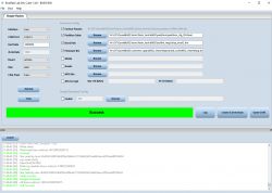
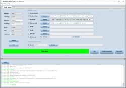
    Thank you very much!

    I think the trick was, to set the Baud from 2M to 500k
    Tasmota replacement for BL602, programming, pairing with Home Assistant, now with OTA working!
    And the Boot PIN (GPIO08) seems to be the right one, it is the LOG spot on the mainboard, which is identical with the connection coming from the daughterboard just beside (the last contact):
    Tasmota replacement for BL602, programming, pairing with Home Assistant, now with OTA working!
    And I had to set the BOOT Pin (over a 10k resistance) to PLUS (not GND) and switch off-on, then keep it on PLUS (3V3) and then flash. After flashing only I disconnected the Boot-Pin from Plus.

    I first used to flash a cheap FT232RL which has insufficient 3V3 supply (as I read in Tasmota support) but it is enough to flash.
    To run it and to set up an accesspoint it seems really to weak on its chest, so I switched to a NodeMCU as described in Tasmota. On the NodeMCU I shortcut the EN-Pin to GND and I dont cross RX-TX but put RX from NodeMCU directly to RX (and TX...) from my BL602 Chip. A NodeMCU is much more reliable.
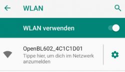
    Only then I found the OpenBL602 AP.
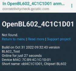
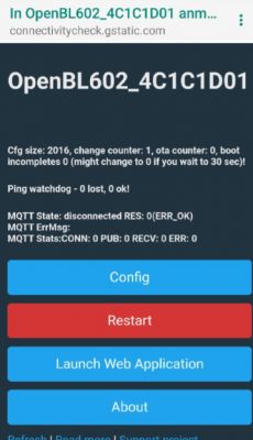
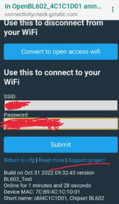
    In my phone I connected now to the OpenBL602_... network, tapped to login (switch to the welcome page) and then I could enter my home WiFi:
    Tasmota replacement for BL602, programming, pairing with Home Assistant, now with OTA working!
    Tasmota replacement for BL602, programming, pairing with Home Assistant, now with OTA working!
    Tasmota replacement for BL602, programming, pairing with Home Assistant, now with OTA working!
    Tasmota replacement for BL602, programming, pairing with Home Assistant, now with OTA working!
    Then I restart the BL602 and it logged successfully into my WiFi. Here I searched it in my router's network (FritzBox) and found it under 192.168.0.115 and on this site I could config it:
    Tasmota replacement for BL602, programming, pairing with Home Assistant, now with OTA working!
    Heureka! I didnt believe that I would get it done finally :)

    Now I have one central question, I think I overread it in the 200 first posts :( - how can I just and simple switch on and off with an URL command (without MQTT) the only relay which this switch has on board, so just to use it as it is but with my (your) own firmware?
    I didnt find it in the millions of settings.

    Added after 1 [hours] 9 [minutes]:

    francwalter wrote:
    Now I have one central question, I think I overread it in the 200 first posts - how can I just and simple switch on and off with an URL command (without MQTT) the only relay which this switch has on board, so just to use it as it is but with my (your) own firmware?
    I didnt find it in the millions of settings.

    OK, I try and errored some in Config > Config Module and found 24 Pins to configure, P0 to P23. I could set them to:

    Spoiler:
    Rel
    Rel_n
    Btn
    Btn_n
    LED
    LED_n
    PWM
    WifiLED
    WifiLED_n
    Btn_Tgl_All
    Btn_Tgl_All_n
    dInput
    dInput_n
    TglChanOnTgl
    dInput_NoPullUp
    dInput_NoPullUp_n
    BL0937SEL
    BL0937CF
    BL0937CF1
    ADC
    SM2135DAT
    SM2135CLK
    BP5758D_DAT
    BP5758D_CLK
    BP1658CJ_DAT
    BP1658CJ_CLK
    PWM_n
    IRRecv
    IRSend
    Btn_NextColor
    Btn_NextColor_n
    Btn_NextDimmer
    Btn_NextDimmer_n
    AlwaysHigh
    AlwaysLow


    But none of them did switch on my relay, only the LED I could toggle with Rel_n but not the relay. Or I dont understand this system at all :(
  • #192 20270838
    p.kaczmarek2
    Moderator Smart Home
    Good job with figuring it out. Now when it comes to configuration...

    You need to know which pin is used for relay. Then just set this pin role for Relay, and you will get a button on GUI that switches this relay.

    It works the same for LED - if you can toggle LED that way, it means the relay might be just on the other pin. Check the PCB or try each pin one by one.
    Helpful post? Buy me a coffee.
  • #193 20270854
    francwalter
    Level 7  
    p.kaczmarek2 wrote:
    ... - if you can toggle LED that way, it means the relay might be just on the other pin. ...
    Unfortunately the Rel pin doesnt work. This was my first attempt, but only the LED on Rel_n works :(

    EDIT: I followed with the multimeter the spot where I read "RELAY0" and I think it is GPIO22, the PIN Number 31 in your picture above.
    But this does not help a lot :(
  • #194 20270997
    p.kaczmarek2
    Moderator Smart Home
    Are you 100% sure about that? Can you please check for any potential wiring errors?
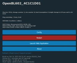
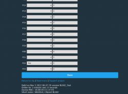
    Tasmota replacement for BL602, programming, pairing with Home Assistant, now with OTA working!
    Tasmota replacement for BL602, programming, pairing with Home Assistant, now with OTA working!
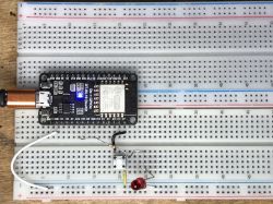
    BL602 dev board with connections:
    Tasmota replacement for BL602, programming, pairing with Home Assistant, now with OTA working!
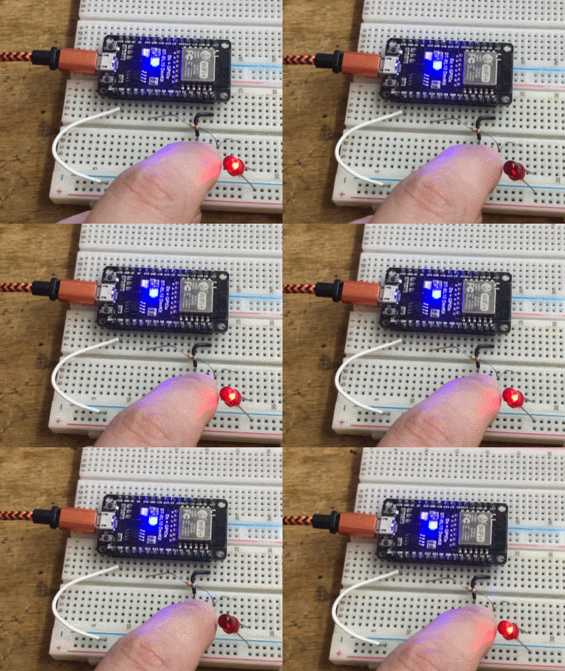
    BL602 microcontroller connected to a breadboard with a flashing LED.
    NOTE: here I also configured a button pin, but a clickable button on WWW page also works.

    It just works...


    well. One of the possibilities is that you are currently powering board with 5V or with 3.3V and relay is using 12V or something like that, so it can't "click". You might need to disconnect programmer and power the board how it is supposed to done to get relay working.

    The other thing you can do, is to disconnect the mains power (important, for safety) and then probe with multimeter pin 22 and check if it has a low or high state (0V or 3.3V) and does it change when you click button on GUI...
    Helpful post? Buy me a coffee.
  • #195 20271047
    francwalter
    Level 7  
    p.kaczmarek2 wrote:
    Are you 100% sure about that? Can you please check for any potential wiring errors?
    Tasmota replacement for BL602, programming, pairing with Home Assistant, now with OTA working!
    Tasmota replacement for BL602, programming, pairing with Home Assistant, now with OTA working! ...

    YEAHH!!!
    Your picture made it immediately clear :)
    PIN 22 is just P22! I didnt check this until I saw your picture and after going to find the right pin for the relay on the pcb.
    Before I just combined anything (try&error) on any P0-P23 because I didnt realize that these are the pins, shame on me :(

    Now I put P1 to the LED (Rel_n) and P22 to the relay (Rel) and it works :)
    Furthermore I put P0 to Rel_n and P1 to LED
    Tasmota replacement for BL602, programming, pairing with Home Assistant, now with OTA working!
    ...
    Tasmota replacement for BL602, programming, pairing with Home Assistant, now with OTA working!
    now I have blue when off and red when on, great, exactly what I need :)
    Thank again.

    Now I need to know how I can toggle with HTTP commands, as in Tasmota, possible?

    EDIT: Found it! it is just an URL Parameter 192.168.0.115/index?tgl=1 Tasmota replacement for BL602, programming, pairing with Home Assistant, now with OTA working!
  • #196 20271059
    p.kaczmarek2
    Moderator Smart Home
    You can do like in Tasmota, but please read Readme, there is a list of commands:
    http://192.168.21.100/cm?cmnd=toggleChannel%200

    http://192.168.0.100/cm?cmnd=led_enableAll%201

    Also please be aware that HTTP requires you to use special characters in some cases, for example, %20 is a space.
    Helpful post? Buy me a coffee.
  • ADVERTISEMENT
  • #197 20271121
    francwalter
    Level 7  
    Still one thing unclear: the button on the device, when I press it, it should manually toggle the relay (and LED color).
    Is this possible?
    At the moment nothing happens if I press it. But this is quite important, without manual switch it is nearly not useable.
  • #198 20271195
    p.kaczmarek2
    Moderator Smart Home
    So which pin is the button pin?
    Helpful post? Buy me a coffee.
  • #199 20271294
    francwalter
    Level 7  
    p.kaczmarek2 wrote:
    So which pin is the button pin?

    My multimeter says GPIO5, the switch ("S1") has 4 pins, two each seem to be connected, so not a bipolar switch, just on-off (first I had a broken jumper cable (with interruption), never had that before, took me a while to check).
    The contacts on the border are GND and the other side is 0 Ohm to Pin 6 of the BL602 so that is GPIO5:
    Tasmota replacement for BL602, programming, pairing with Home Assistant, now with OTA working!
    But what can I do if I know this? YESS! I can connect P5 to Btn_Tgl_All:

    Tasmota replacement for BL602, programming, pairing with Home Assistant, now with OTA working!

    AND IT DOES :) :) :)
    Tadaaa!
    All set. Thank again and again :)
  • #200 20271297
    omelchuk890
    Level 11  
    @francwalter
    Link
    I hope you catch the meaning of "channels"
  • #201 20271335
    francwalter
    Level 7  
    omelchuk890 wrote:
    @francwalter
    Link
    I hope you catch the meaning of "channels"

    I have only one relay on board, so I stick with channel 1, so I hope I understood it :)
    EDIT: Channel 0 does the same in my case.

    At the moment I did flash (with SUCCESS) the second of my 4 Switch-WF :) :)
    ... and the fourth :)
  • #202 20272121
    francwalter
    Level 7  
    Is it possible to make the status answer so verbose as the Tasmota status?
    When I ask status 0 with:

    http://192.168.0.221/cm?cmnd=STATUS%200

    this gives me only:

    {"Status":{"Module":0,"DeviceName":"obl4C1C1D01","FriendlyName":["OpenBL602_4C1C1D01"],"Topic":"obl4C1C1D01","ButtonTopic":"0","Power":1,"PowerOnState":3,"LedState":1,"LedMask":"FFFF","SaveData":1,"SaveState":1,"SwitchTopic":"0","SwitchMode":[0,0,0,0,0,0,0,0],"ButtonRetain":0,"SwitchRetain":0,"SensorRetain":0,"PowerRetain":0,"InfoRetain":0,"StateRetain":0}}

    But not also StatusPRM, StatusSNS, StatusTIM, StatusSTS, StatusPTH, StatusFWR, StatusLOG, StatusMEM, StatusNET, StatusMQT

    I wouldn't care but an app I use, Tasmota Remota, crashes because of that.
    Thanks.
  • #203 20272565
    p.kaczmarek2
    Moderator Smart Home
    That's a great sugestion. I was not aware about that issue. I can look into that very soon. Can you tell me where to get that App so I can test things myself?
    Helpful post? Buy me a coffee.
  • #204 20272685
    francwalter
    Level 7  
    p.kaczmarek2 wrote:
    That's a great sugestion. I was not aware about that issue. I can look into that very soon. Can you tell me where to get that App so I can test things myself?

    The App is called TasmotaRemota, hier the Link: TasmotaRemota

    The Dev is calling in his network scan the status 0 and uses several of the sections. They are missing in OpenBL602 so his app crashes (!).
    At the very moment he fixes this bug, but wont be able to include OpenBL602 to his controllable Tasmota devices.

    He wrotes me (I put it into a spoiler, its too much text):
    Spoiler:

    Quote:
    I see thet even if all the status lists are made available, the command structure for operating these is different to Tasmota.
    And ... no timers or Pulsetime.
    So, as I said - it will never work with a Tasmota HTTP app.

    and:
    Quote:
    A scan uses "STATUS 0" to find all the fields needed for the device.
    TasmotaRemota then knows how to display the device in the found devices list (ie. relay, switch sensor type etc )
    The app is crashing because it cannot find the json list "StatusTIM", "StatusSNS" or "StatusSTS".
    These lists must be present to fully ID the type of device (relay, switch, sensor type etc), and its present state. (ON/OFF,Temp values etc).
    It searches these lists for specific details of any selected device, ready to add to the internal device database.
    Once a relay device is selected, it will then search for more data for the Timers, Pulsetime. These are always available for a "real" Tasmota device.
    Once a device is placed into a group, TasmotaRemota will pole the device every 5 seconds with a STATUS call to get an update of its status (ON/OFF/Temp/wifi signal etc) and update the display.
    A relay device can be operated using the standard Tasmota commands "POWER ON, POWER OFF, POWER TOGGLE" then "POWER" to confirm the new relay state.
    None of this required data is available in the pseudo Tasmota Device/firmware you are using, so it will never work with ANY Tasmota HTTP control apps.


    and the status of a real Tasmota he made an example:

    Quote:
    Your Status information does not contain any detail about the actual status of the device, so I cannot read anything into TasmotaRemota, so you will get crashes whenever you try this device.
    The full details are shown below (I have split it into the Status sections so you can clearly see the info that is given) - ALL Tasmota devices have this information available. This is how they work.
    The only section that your device is sending is the first "Status", so it cannot be used by either the Tasmota WebUI or TasmotaRemota.
    Sorry I cannot help you with this.
    {
    "Status":{"Module":43,"DeviceName":"Door Lamp","FriendlyName":["Door Lamp"],"Topic":"door-lamp","ButtonTopic":"0","Power":1,"PowerOnState":3,"LedState":1,"LedMask":"FFFF","SaveData":1,"SaveState":1,"SwitchTopic":"0","SwitchMode":[0,0,0,0,0,0,0,0],"ButtonRetain":0,"SwitchRetain":0,"SensorRetain":0,"PowerRetain":0,"InfoRetain":0,"StateRetain":0,"StatusRetain":0},

    "StatusPRM":{"Baudrate":4800,"SerialConfig":"8E1","GroupTopic":"tasmotas","OtaUrl":"http://ota.tasmota.com/tasmota/release/tasmota.bin.gz","RestartReason":"Software/System restart","Uptime":"4T08:20:02","StartupUTC":"2022-11-02T10:31:59","Sleep":50,"CfgHolder":4617,"BootCount":251,"BCResetTime":"2021-01-21T19:46:47","SaveCount":16446,"SaveAddress":"F6000"},

    "StatusFWR":{"Version":"12.2.0(tasmota)","BuildDateTime":"2022-10-17T08:39:23","Boot":31,"Core":"2_7_4_9","SDK":"2.2.2-dev(38a443e)","CpuFrequency":80,"Hardware":"ESP8266EX","CR":"423/699"},

    "StatusLOG":{"SerialLog":0,"WebLog":2,"MqttLog":2,"SysLog":0,"LogHost":"","LogPort":514,"SSId":["VILLIAN","VILLIAN"],"TelePeriod":60,"Resolution":"558180C0","SetOption":["00028009","2805C80001800680003C5A0A002800000000","00008289","00006000","00004000","00000000"]},

    "StatusMEM":{"ProgramSize":626,"Free":376,"Heap":21,"ProgramFlashSize":1024,"FlashSize":1024,"FlashChipId":"1440E0","FlashFrequency":40,"FlashMode":"DOUT","Features":["00000809","8F9AC787","04368001","000000CF","010013C0","C000F981","00004004","00001000","54000020","00000000"],"Drivers":"1,2,3,4,5,6,7,8,9,10,12,16,18,19,20,21,22,24,26,27,29,30,35,37,45,62","Sensors":"1,2,3,4,5,6"},

    "StatusNET":{"Hostname":"door-lamp-1703","IPAddress":"192.168.1.12","Gateway":"192.168.1.1","Subnetmask":"255.255.255.0","DNSServer1":"192.168.1.1","DNSServer2":"0.0.0.0","Mac":"60:01:94:1E:46:A7","Webserver":2,"HTTP_API":1,"WifiConfig":4,"WifiPower":17.0},

    "StatusMQT":{"MqttHost":"192.168.1.25","MqttPort":1883,"MqttClientMask":"DVES_%06X","MqttClient":"DVES_1E46A7","MqttUser":"Villard","MqttCount":6,"MAX_PACKET_SIZE":1200,"KEEPALIVE":30,"SOCKET_TIMEOUT":4},

    "StatusTIM":{"UTC":"2022-11-06T18:52:01","Local":"2022-11-06T19:52:01","StartDST":"2022-03-27T02:00:00","EndDST":"2022-10-30T02:00:00","Timezone":99,"Sunrise":"07:40","Sunset":"17:28"},

    "StatusPTH":{"PowerDelta":[0,0,0],"PowerLow":0,"PowerHigh":0,"VoltageLow":0,"VoltageHigh":0,"CurrentLow":0,"CurrentHigh":0},

    "StatusSNS":{"Time":"2022-11-06T19:52:01","ENERGY":{"TotalStartTime":"2020-07-31T09:42:09","Total":0.000,"Yesterday":0.000,"Today":0.000,"Power":0,"ApparentPower":0,"ReactivePower":0,"Factor":0.00,"Voltage":0,"Current":0.000}},

    "StatusSTS":{"Time":"2022-11-06T19:52:01","Uptime":"4T08:20:02","UptimeSec":375602,"Heap":22,"SleepMode":"Dynamic","Sleep":50,"LoadAvg":19,"MqttCount":6,"POWER":"ON","Wifi":{"AP":1,"SSId":"VILLARD","BSSId":"5C:A8:6A:3F:EC:60","Channel":9,"Mode":"11n","RSSI":56,"Signal":-72,"LinkCount":2,"Downtime":"0T00:00:07"}}}
  • #205 20273839
    Maniac2002
    Level 6  
    Hello,
    today i flashed also my Switch WF.
    Unfortunally i have made a mistake in cofiguring the wifi.
    Now it can not connect to the Network.

    ===start sm_get_bss_params===
    bssid[0] = 0xffff
    bssid[1] = 0xffff
    bssid[2] = 0xffff
    search ssid = DONTCARE
    result ssid index = -1
    ===end sm_get_bss_params===
    [WF][SM] Entering connecting state
    [APP] [EVT] Reconnect 211879
    [APP] [EVT] Reconnect 211879
    [APP] [EVT] Connecting 211879
    [APP] [EVT] Connecting 211879
    Info:MAIN:Main_OnWiFiStatusChange - WIFI_STA_CONNECTING
    [23:35:23.168] - Info:MAIN:Time 211, idle 0/s, free 10825, MQTT 0(0), bWifi 0, secondsWithNoPing -1, socks 2/21
    [23:35:24.159] - Info:MAIN:Time 212, idle 0/s, free 108256, MQTT 0(0), bWifi 0, secondsWithNoPing -1, socks 2/21
    [23:35:25.164] - Info:MAIN:Time 213, idle 0/s, free 108256, MQTT 0(0), bWifi 0, secondsWithNoPing -1, socks 2/21
    [23:35:25.616] - ===start sm_get_bss_params===
    bssid[0] = 0xffff
    bssid[1] = 0xffff
    bsid[2] = 0xffff
    search ssid = DONTCARE
    result ssid index = -1
    ===end sm_get_bss_params===
    ind ix 0x42028cbc, chan_ctxt is 0x00000000
    connect fail
    ure, ssid = DONTCARE , index = -1
    [RX] Connection Status
    [RX] status_code 12
    [RX] connect result: SSID error
    , scan no bssid and channel
    [RX] MAC 00:00:00:00:00:00
    [RX] vif_idx 0
    [RX] ap_idx 255
    [RX] ch_idx 0
    [RX] qos 0
    [RX] acm 0
    [RX] assoc_req_ie_len 0
    [RX] assoc_rsp_ie_len 0
    [RX] aid 0
    [RX] band 0
    [RX] center_freq 0
    [RX] width 0
    [RX] center_freq1 0
    [RX] center_freq2 0
    [WF][SM] Exiting connecting state
    [WF][SM] State Action ###connecting### --->>> ###disconnect###
    [WF][SM] Entering disconnect state
    [WF][SM] Will retry in 2000 ticks
    [APP] [EVT] disconnect 215143, Reason: SSID error

    Does anybody know how to reset the WIFI configuration?.
    best regards an Thanks in advance
    Maniac2002
  • #206 20274096
    p.kaczmarek2
    Moderator Smart Home
    @francwalter I will try to look into it very soon, but it's not good that his app crashes when a single block is missing. He should be checking for null pointers. Also, what about Tasmota Control? Is it crashing as well?

    @Maniac2002 first thing to try is to do quick 5 power on and off cycles in order for device to go back to safe AP mode.
    WARNING: in safe AP mode the pinout of device is disabled! Relay will not work! it's for recovering device from bad config
    Helpful post? Buy me a coffee.
  • #207 20275609
    francwalter
    Level 7  
    p.kaczmarek2 wrote:
    @francwalter I will try to look into it very soon, but it's not good that his app crashes when a single block is missing. He should be checking for null pointers. Also, what about Tasmota Control? Is it crashing as well?
    You mean the old (last update: 2020) App Tasmota Remote (id=de.grings_software.TasmotaControl)?
    Here I get:
    Connection: Wrong answer (no Tasmota found)! But the app does not crash.
    I agree, it is not so good programming if an app can crash because it doesn't get exactly what it expected, must catch the possible errors, I think.
    But dont worry much, I will skip all apps to control my Tasmota and my BL602 devices, I decided now, and I made simple HTTP Shortcuts (with the great app "HTTP Shortcuts").
    Or I will use Tasker where I can control (maybe) even more. I dont need an app which calls all x seconds the net (and drains my battery) just to let me know if my device is on or off etc.
  • #208 20276458
    p.kaczmarek2
    Moderator Smart Home
    @francwalter I am doing OpenBeken port to Windows platform for ease of development and to allow users get a demo of our firmware without installing it on SOC, when I finish I will look into supporting all those Tasmota apps. It's easier and faster when you can run software directly on your PC.

    @francwalter would you have time to help testing Tasmota Remota etc support in few days?
    Helpful post? Buy me a coffee.
  • #209 20276474
    Maniac2002
    Level 6  
    Hello.

    I can also support you in testing the tasmota remote if you like.

    Best regards Maniac2002
  • #210 20276853
    francwalter
    Level 7  
    p.kaczmarek2 wrote:
    @francwalter I am doing OpenBeken port to Windows platform for ease of development and to allow users get a demo of our firmware without installing it on SOC, when I finish I will look into supporting all those Tasmota apps. It's easier and faster when you can run software directly on your PC.

    @francwalter would you have time to help testing Tasmota Remota etc support in few days?

    Yes! Thank you! After weekend spare time :)

Topic summary

The discussion revolves around the development and integration of firmware for devices based on the BL602 chip, particularly focusing on flashing procedures, MQTT connectivity, and Home Assistant integration. Users share their experiences with various models, including Magic Home LED controllers and Sonoff devices, detailing successful flashing processes, issues with WiFi connectivity, and the need for stable power supplies. The conversation also touches on the implementation of features like OTA updates, Alexa integration, and the challenges faced with different firmware versions. Users report on the behavior of their devices post-flashing, including boot loops and MAC address duplication issues, while seeking solutions and sharing troubleshooting tips.
Summary generated by the language model.
ADVERTISEMENT