logo elektroda
logo elektroda
X
logo elektroda

Tasmota replacement for BL602, programming, pairing with Home Assistant, now with OTA working!

p.kaczmarek2 123654 497
ADVERTISEMENT
Treść została przetłumaczona polish » english Zobacz oryginalną wersję tematu
  • #211 20277622
    p.kaczmarek2
    Moderator Smart Home
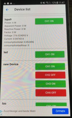
    I have started improving Tasmota Control support (Tasmota Control and Tasmota Remota, it's the same protocol).
    I. e. I try to support:
    
    http://192.168.0.103/cm?cmnd=status


    http://192.168.0.103/cm?cmnd=POWER2%20OFF
    

    etc
    I got working:
    - power ON/OFF LED strip and bulbs etc (almost)
    - control power of relays of single relay and multi relay devices
    - read power from power metering sockets
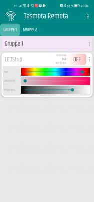
    Screenshot:
    Tasmota replacement for BL602, programming, pairing with Home Assistant, now with OTA working!
    but I have a strange problem.
    I am testing with single color ESP8266 LED strip, but this LED strip doesn't show as a strip on Tasmota Control, same for Tasmota Remota.
    My question to you guys - are LED strips (single color or multi color) and/or RGB, CW, RGBCW bulbs supported by Tasmota control or Tasmota Remota?

    Question 2: Can anyone paste here me the JSON replies of Tasmota devices with a) single color led, b) RGB LED c) RGBCW led d) CW led, strips bulbs or anything, for::
    
    http://192.168.0.103/cm?cmnd=status


    http://192.168.0.103/cm?cmnd=status 8
    
    Helpful post? Buy me a coffee.
  • ADVERTISEMENT
  • #212 20278296
    roli1
    Level 6  
    I have a Gosund LED Strip Model SL2 flashed with Tasmota.
    The output of
    
    http://192.168.0.103/cm?cmnd=status


    {
    Status: {
    Module: 0,
    DeviceName: "LEDStrip",
    FriendlyName: [
    "LEDStrip"
    ],
    Topic: "LED_Strip",
    ButtonTopic: "0",
    Power: 0,
    PowerOnState: 3,
    LedState: 1,
    LedMask: "FFFF",
    SaveData: 0,
    SaveState: 1,
    SwitchTopic: "0",
    SwitchMode: [
    0,
    0,
    0,
    0,
    0,
    0,
    0,
    0
    ],
    ButtonRetain: 0,
    SwitchRetain: 0,
    SensorRetain: 0,
    PowerRetain: 1,
    InfoRetain: 0,
    StateRetain: 0
    }
    }


    and
    
    http://192.168.0.103/cm?cmnd=status 8


    {
    StatusSNS: {
    Time: "2022-11-10T20:42:07"
    }
    }
    

    In Tasmota remota the device is shown as RGBCW device
    Tasmota replacement for BL602, programming, pairing with Home Assistant, now with OTA working!
  • #213 20278702
    p.kaczmarek2
    Moderator Smart Home
    Thanks, what about Tasmota Control?
    Futhermore, where is the RGB value stored? From a quick glance, I can't see it on your screenshots.
    Helpful post? Buy me a coffee.
  • #214 20279033
    roli1
    Level 6  
    If i change the color the output in the Tasmota console is
    
    11:42:33.021 MQT: stat/LED_Strip/RESULT = {"POWER":"ON","Dimmer":100,"Color":"255,0,157","HSBColor":"323,100,100","Channel":[100,0,62]}


    Added after 9 [minutes]:

    
    http://10.0.0.59/cm?cmnd=HSBColor


    {
    POWER: "OFF",
    Dimmer: 100,
    Color: "255,0,157",
    HSBColor: "323,100,100",
    Channel: [
    100,
    0,
    62
    ]
    }


    http://10.0.0.59/cm?cmnd=Color


    {
    Color: "255,0,157"
    }
    
  • ADVERTISEMENT
  • #215 20279982
    p.kaczmarek2
    Moderator Smart Home
    Thank you, this is a very useful information.

    roli1 wrote:

    
    {
    POWER: "OFF",
    Dimmer: 100,
    Color: "255,0,157",
    HSBColor: "323,100,100",
    Channel: [
    100,
    0,
    62
    ]
    }
    

    May I ask what happens if you set the dimmer down to 10 instead of 100?
    Or to be more specific, are the "Color" values already scaled by dimmer or are they 'raw', before calling?
    Helpful post? Buy me a coffee.
  • #217 20297161
    francwalter
    Level 7  
    Hallo
    I have now one of my BL602 in use since I flashed it, works great :)
    I made a widget in Tasker (an Android automation app) where I send:
    http://192.168.0.221/cm?cmnd=Power TOGGLE

    This works good, as answer I just get the new Power state, e.g.
    {"POWER":"ON"}
    which I can use to change the widget color and text.
    But often, due to problems of my phone with WiFi in our flat (too large for one wifi-router therefore a repeater and then the phone switches all the time between the two, disconnecting sometimes totally), I press the widget in vain so I switch the BL602 manually (yes, this is still possible, and often much faster than grabbing the phone). So the widget doesnt change although the state changed (ON or OFF).
    I would like to get just the power state now, to set the widget right, but I dont get it, in status, the power is always 1, e.g.:
    http://192.168.0.221/cm?cmnd=Power%20OFF
    {"POWER":"OFF"}
    http://192.168.0.221/cm?cmnd=status
    {"Status":{"Module":0,"DeviceName":"OpenBL602-1","FriendlyName":["OpenBL602_4C1C1D01"],"Topic":"obl4C1C1D01","ButtonTopic":"0","Power":1,"PowerOnState":3,"LedState":1,"LedMask":"FFFF","SaveData":1,"SaveState":1,"SwitchTopic":"0","SwitchMode":[0,0,0,0,0,0,0,0],"ButtonRetain":0,"SwitchRetain":0,"SensorRetain":0,"PowerRetain":0,"InfoRetain":0,"StateRetain":0}}

    If I do a toggle again, Power still is 1.
    How can I just check whether the switch is on or off without switching it?
  • #218 20297186
    p.kaczmarek2
    Moderator Smart Home
    Hello @francwalter , which version are you using? I have recently upgraded JSON support to contain all necessary information.
    Helpful post? Buy me a coffee.
  • #219 20297196
    francwalter
    Level 7  
    p.kaczmarek2 wrote:
    Hello @francwalter , which version are you using? I have recently upgraded JSON support to contain all necessary information.

    It says: Build on Oct 31 2022 09:32:43 version BL602_Test
    So I will try an OTA Update, never did yet, hopefully it works ...

    Added after 20 [minutes]:

    francwalter wrote:
    ...It says: Build on Oct 31 2022 09:32:43 version BL602_Test
    So I will try an OTA Update ...

    No, does not seem to work. I put it on my server (where I can use http) and put the link to the bin file into the OTA field, after pressing the Button: OTA (update software by WiFi), but it says just:
    Quote:

    but the OTA Update is not done. Anyway it is not a RBL file, the firmware is a BIN file, so that cannot work I guess :(

    In the app (Button: Launch Web Application) I could download the (same) bin from the dropdown, but then, when I select the downloaded OpenBL602_1.15.70.bin file, I can read:
    Quote:
    OpenBL602_1.15.70.bin len:789804
    Invalid OTA file was selected

    The file filter in the file selection dialog is .img though, so why is there a dropdown with the bin files when it needs a img (or rbl???) file?
    I am confused. Where can I read about OTA firmware update of BL602? Is it possible at all?
    I dont understand the instructions in OTA :( Where can I find the firmware as RBL-file?

    I dont want to solder again the pins, please dont let me do this :(
  • #220 20297269
    p.kaczmarek2
    Moderator Smart Home
    You have old version.
    Tasmota replacement for BL602, programming, pairing with Home Assistant, now with OTA working!
    Many changes were added on, for example, Nov 10, 2022.

    Sadly OTA (as you can read in this thread) is not present on BL602, because it was not present in the SDK we used. They really didn't have OTA working, at least at the time of forking. Only BK7231T, BK7231N, W600 (601), W800 (801) have OTA working.
    Helpful post? Buy me a coffee.
  • #221 20297310
    francwalter
    Level 7  
    p.kaczmarek2 wrote:
    ...
    Sadly OTA (as you can read in this thread) is not present on BL602, because it was not present in the SDK we used...

    Ok, I see. Thank. Maybe one day I will flash then by cable again, but a bit unlikely, too much work for too few advantage, I guess I will live with it ;)
    EDIT: or I could just get the index and with some JS:
    document.getElementById("state").firstChild.firstChild.firstChild.firstChild.innerHTML

    This is OFF or ON, depending on the state.
    p.kaczmarek2 wrote:
    ...as you can read in this thread...
    Yes, now I found it :) When searching for OTA in this thread, it appears in # 162
  • ADVERTISEMENT
  • #222 20304920
    bobbik
    Level 17  
    Hello. I admit that I only briefly looked through github and this thread, so I`ll ask if:
    - there is still no ota for BL602?
    - Is it possible to use the same GPIO for short and long button presses?
    - and multiclick? (E.g. 3 clicks?)
    - are any simple automations possible?
    (E.g. using the button always turns on the W channel regardless of the last color but at the brightness last used)
  • #223 20306690
    p.kaczmarek2
    Moderator Smart Home
    @bobbik OTA is only for BK7231T/N, W600/601, W800/801 etc. BL602 did not have it in the SDK used and there are only a few devices on BL602, so there were no further attempts to add it. Unless you found some new device for BL602?

    Button events can be freely scripted, you can attach any command to them, separately for click, separately for double click, hold start, and so on. You can create events in "Short startup command"

    Automation can also be done through events. In the case of BK, there are also full-fledged LittleFS scripts, but we haven`t run LittleFS on BL602 yet because it was never needed, but I can add it if someone wants to create more complex mechanisms (you can check conditions in the scripts, wait a certain amount of time, etc.)

    What exactly do you need to do?
    Helpful post? Buy me a coffee.
  • ADVERTISEMENT
  • #224 20313915
    droege
    Level 10  
    Hi there again,

    after quite a long time, I have tested the new version again. I flashed today by wire the new version 1.15.120 in the BL602.
    First of all, I can report, that the MQTT Bug has been fixed. Great work. The device seems to be stable.
    Flashing from 1.12.x seems to result in a complete reset of all parameters, including wifi data, etc. I had to start from scratch configuring all the data.
    Which is fine, if this would be documented.
    A complete documentation of MQTT commands (including basecolor and finalcolor) is still missing. Would be great to have this, in order to support other system than Home Assistant. I'm using FHEM, wich works great, if only I could read the syntax somewhere.

    One feature, I'm still missing, I have requested many times, is:
    - recalculate and pulish dimmer values.
    As an explanation:
    final color computes from basecolor & dimmer a final color, if needed. Fine, if dimmer is changed on a given basecolor.
    But if you now set, given you have set basecolor to FF0000 (red) and dimmer to 50% (which results in 7f0000), a new basecolor, the dimmer is still on 50%.
    This is in my opinion wrong, as the RGB value contains a new dimmer value. Let's say you set a new basecolor (or finalcolor if you want) like FF0000, this means 100% red (or first channel). This is 100% of the first channel. No meaning of applying a previously set dimmer, as you set explicitly a new RGB value. Tasmota is working like this.

    Can you please reset the dimmer value (and publish via MQTT) with a new RGB_basecolor and overwrite the dimmer value with this. Because a new RGB is including a new dimmer value. You could also tell this a new finalcolor if you like. Both are fine, but I would like to get rid of a previously defined dimmer value by setting a new RGB. Tasmota is doing it like this.

    Thanks,
    kind regards,
    Olaf

    Added after 9 [minutes]:

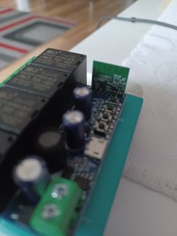
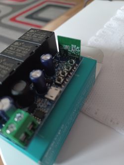
    Hi again,

    sorry, I have another request.
    You have added a control bit, that allows to enable light whenever brightness, color, etc. is changed on the web-interface.
    Can you enhance this to MQTT.
    Whenever I change color or temperature on tasmota, the device is switched on, also via MQTT.
    Would be great, if you could extend this feature also to MQTT.
    And if you do this, can you report also via finalcolor, and not only on basecolor? A system has to choose , where to get the color information from. And if it is finalcolor (due to dimmer, etc.) this should be consistent.

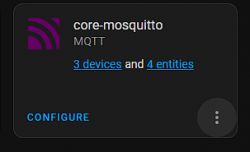
    Thanks,
    best,
    Olaf
  • #225 20325354
    davidcpurdy
    Level 7  
    bxwen19 wrote:
    I finally got some time to figure out most of the pins of sonoff S40 . The LEDs and relay are verified to be working as expected. I am not sure how to set the power monitoring device though. GPIO pin 14 is connected to cse7759b tx pin. It is supposed to receive readout from the chip. Which one should I choose?


    After some messing around, I've gotten as far as @bxwen19 has gotten I think...

    Confirmed on Sonoff S40 :
    -Used the 1.4.8 BLDevCube.exe, properly located in the flash_tools folder, on a Windows 10 laptop
    -Had to dig through the thread to find the specific post where the author's correct/anointed version 1.4.8 resided
    -Flashed OpenBL602_1.15.149.bin from Link - OpenBL602_1.15.149.bin
    -Used TX0 and RX0, worked for flashing (*not* TX1 and RX1, notably)
    -Used an FTDI USB-Serial converter
    -Used the 5V power supply from the FTDI to power the 5V pad on the daughter board
    -Confirmed that the on-daughterboard power converted stepped 5V down to 3.3V correctly
    -Bridged from 3.3V pad on daughter board to the Boot pad with a 10k resister to enable flashing
    -Once my wiring, software and files were in order, the actual flashing is quite fast... after which I rebooted the device...
    -Required powering off/on many times, and some nervous waiting, until the Access Point "OpenBL602_BLAHBLAH" appeared...
    -WiFi access point connects correctly, has IP 192.168.169.1 , serves address to clients connecting as expected
    -Read over the datasheet "BL602_BL604_DS_1.6_en.pdf" and most of this thread a few times...

    Still to do:
    -get led working
    -get relay working
    -flash with latest OpenBL602 image : OpenBL602_1.15.158.bin
    -get power monitoring working
    -test MQTT
    -integrate into HomeAssistant - Discovery of this device in MQTT by HomeAssistant was easy and painless.

    ============================================
    followup...


    After considerable messing around, here is a summary of a working (but incomplete) Sonoff S40 OpenBL flashing and results.

    I could not get the pins/Gpio mentioned by @bxwen19 (or was unable to interpret his meaning correctly?). I ended up with this:

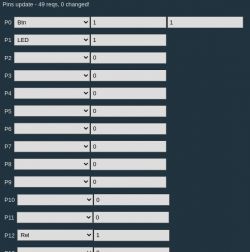
    Configuration data for S40, through the web interface configuration page.

    Pn (per Config page)Role (from dropdown menu)Channel #2nd Channel #GPIO_NAME (per datasheet)
    P0Btn (button)11 PAD_GPIO_0
    P1LED (blue LED2)1 PAD_GPIO_1
    P12Rel (AC mains voltage relay, and red LED1)1 PAD_GPIO_11


    Some notes about behavior of the flashed device:
    - LED1 and LED2 are mutually exclusive in terms of being lit, per programming, I assume.
    - LED2 (blue) signifies that the module is powered on but the relay is OFF.
    - LED1 (red) signifies that the module is powered on and the relay is ON.
    - the logs show that the module, as configured, is correctly registering "button presses", single, long and multiple.

    I would also like to turn on the power monitoring circuitry ans use that in my HomeAssistant setup.

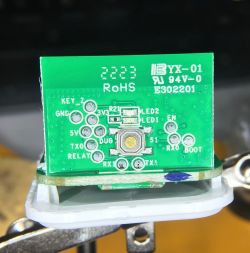
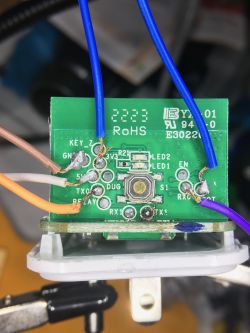
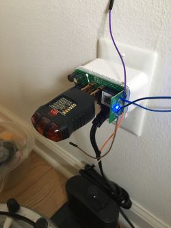
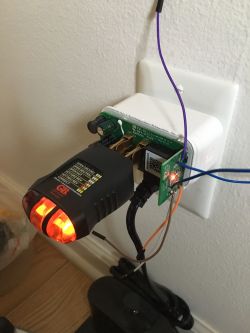
    Attached are some photos also that show:
    - daughterboard
    - daughterboard w/ soldered leads (apologies for nasty solder joints)
    - S40 module w/ relay OFF (blue LED visible)
    - S40 module w/ relay ON (red LED visible)
    - screenshot of configuration page

    Tasmota replacement for BL602, programming, pairing with Home Assistant, now with OTA working!
    Tasmota replacement for BL602, programming, pairing with Home Assistant, now with OTA working! Tasmota replacement for BL602, programming, pairing with Home Assistant, now with OTA working! Tasmota replacement for BL602, programming, pairing with Home Assistant, now with OTA working! Tasmota replacement for BL602, programming, pairing with Home Assistant, now with OTA working!
  • #226 20330045
    p.kaczmarek2
    Moderator Smart Home
    Hello @droege , it's nice to see you again after some time. Yes, it seems we've finally managed to resolve the MQTT issue, or at least make it useable. It's good it works for you.
    Regarding the dimmer issue, I am not sure because no other user reported that change being required. I will forward your suggestion to our git issue tracker.

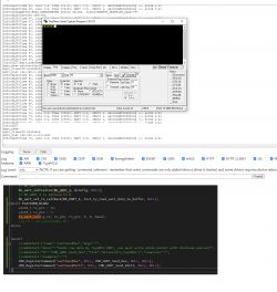
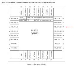
    @davidcpurdy from what I can gather, the IO7 and IO16 were used for flashing the board from the first post in this topic and BL602 SDK. The same port is used for log and commandline.
    So far I have tried to get it running in OBK, but while send works, it seems there might be some issue with receive:
    Tasmota replacement for BL602, programming, pairing with Home Assistant, now with OTA working!
    Receive must be fixed by me first, unless someone here have C knowledge and wants to help?

    Quote:

    GPIO pin 14 is connected to cse7759b tx pin.

    Tasmota replacement for BL602, programming, pairing with Home Assistant, now with OTA working!
    This pin? I will look into changing UART (there are two UARTs on BL602) to use this pin and we will see.

    We will also need to know if cse7759b protocol is the same as cse7766. Maybe if it's at least similar, then cse7766 driver could be adjusted to support both. I haven't looked at the datasheet yet.


    EDIT:
    droege wrote:

    You have added a control bit, that allows to enable light whenever brightness, color, etc. is changed on the web-interface.
    Can you enhance this to MQTT.
    Whenever I change color or temperature on tasmota, the device is switched on, also via MQTT.
    Would be great, if you could extend this feature also to MQTT.

    I am not sure if changing the old flag is a good idea, I would be worried about the DGR. I have added another flag for you that works on any change, but you will need to update the firmware.
    Helpful post? Buy me a coffee.
  • #227 20330257
    davidcpurdy
    Level 7  
    p.kaczmarek2 wrote:
    Receive must be fixed by me first, unless someone here have C knowledge and wants to help?

    My C knowledge/skill/experience is limited (I learned Fortran back in the 70's), no experience writing drivers. ::dave shrugs::

    I will offer one thing I stumbled upon while reading docs/use cases... in ESPHome Sonoff 31, there is brief mention of UART and logging interference:
    # Basic Config
    esphome:
      name: sonoff_s31
      platform: ESP8266
      board: esp01_1m
    ...
    
    logger:
      baud_rate: 0 # (UART logging interferes with cse7766)
      
    # Remove this line if you're not using Home Assistsant or your switch will restart every now and again
    api:
    
    ota:
    
    # Device Specific Config
    
    uart:
      rx_pin: RX
      baud_rate: 4800
    ...
    
    sensor:
      - platform: wifi_signal
        name: "Sonoff S31 WiFi Signal"
        update_interval: 60s
      - platform: cse7766
        current:
          name: "Sonoff S31 Current"
          accuracy_decimals: 1
        voltage:
          name: "Sonoff S31 Voltage"
          accuracy_decimals: 1
    ...

    Not sure this is applicable to our situation, but I thought I'd bring it up. True that it's a different platform/SoC/MCU, but we're talking about the UART connection in either case, right?

    Regarding compatibility of the two chips: ...I have compared the CSE7766 and CSE7759B datasheets and they are very similar...., for what it's worth.
  • #228 20331695
    davidcpurdy
    Level 7  
    Thank you, I see your commit and release 1.15.165. Will flash and report back.
  • #229 20331822
    p.kaczmarek2
    Moderator Smart Home
    1.15.165 for me seems to be only able to send data through UART, no receive yet.
    Helpful post? Buy me a coffee.
  • #230 20331968
    davidcpurdy
    Level 7  
    
    Info:MAIN:Time 29, idle 0/s, free 105136, MQTT 0(0), bWifi 0, secondsWithNoPing -1, socks 3/21
    Debug:API:POST to api/cmnd
    Debug:CMD:cmd [startDriver CSE7766]
    Info:EnergyMeter:Read ENERGYMETER status values. sizeof(ENERGY_METERING_DATA)=40
    Debug:CMD:Adding command EnergyCntReset
    Debug:CMD:Adding command SetupEnergyStats
    Debug:CMD:Adding command ConsumptionThresold
    Debug:CMD:Adding command uartSendHex
    Debug:CMD:Adding command uartSendASCII
    Debug:CMD:Adding command PowerSet
    Debug:CMD:Adding command VoltageSet
    Debug:CMD:Adding command CurrentSet
    Debug:CMD:Adding command PREF
    Debug:CMD:Adding command VREF
    Debug:CMD:Adding command IREF
    Info:MAIN:Started CSE7766.
    Debug:MQTT:MQTT deduper sent 0, culled duplicates 0, culled too fast 0
    Info:MAIN:Time 30, idle 0/s, free 104544, MQTT 0(0), bWifi 0, secondsWithNoPing -1, socks 2/21
    Debug:MQTT:MQTT deduper sent 0, culled duplicates 0, culled too fast 0
    Info:MAIN:Time 31, idle 0/s, free 104544, MQTT 0(0), bWifi 0, secondsWithNoPing -1, socks 2/21
    Info:MAIN:Boot complete time reached (30 seconds)
    Debug:CFG:BL602_SaveFlashVars: saved 64 bytes
    Debug:MQTT:MQTT deduper sent 0, culled duplicates 0, culled too fast 0
    Info:MAIN:Time 32, idle 0/s, free 104544, MQTT 0(0), bWifi 0, secondsWithNoPing -1, socks 2/21
    Debug:MQTT:MQTT deduper sent 0, culled duplicates


    Quote:
    ON
    CSE7766 Voltage=0.000000, Current=0.000000, Power=0.000000, Total Consumption=0.0 Wh (changes sent 0, skipped 0, saved 10)
    Periodic Statistics
    Consumption (during this period): 0.0 Wh
    Sampling interval: 10 sec
    History length: 20 samples
    History per samples:
    0.0, 0.0, 0.0, 0.0, 0.0, 0.0, 0.0, 0.0, 0.0, 0.0, 0.0, 0.0, 0.0, 0.0, 0.0, 0.0, 0.0, 0.0, 0.0, 0.0
    History Index: 0
    JSON Stats: disabled
    NTP driver is not started, daily stats disbled.
    1 drivers active (CSE7766), total 11
    Channel 1 = 1
    Cfg size: 2016, change counter: 5, ota counter: 0, boot incompletes 0 (might change to 0 if you wait to 30 sec)!


    This is what I'm seeing. (My soldering iron is attached and is hot, so I know it is drawing current.)

    Added after 8 [hours] 28 [minutes]:


    p.kaczmarek2 wrote:
    @davidcpurdy from what I can gather, the IO7 and IO16 were used for flashing the board from the first post in this topic and BL602 SDK. The same port is used for log and commandline.
    So far I have tried to get it running in OBK, but while send works, it seems there might be some issue with receive:


    Two thoughts:

    1. Any chance that you could use UART Port 1 instead of Port 0?

    A few docs I looked at mention that UART0 ( tx=16, rx=7) is reserved for CLI and console. They used UART1 (tx=4, rx=3) for data transfer, as in this BL602 + E-Ink Display using UART.


    2. In the CSE7766.c driver, I can find where PREF and IREF are defined. I couldn't find the same sort of define for VREF, though.
  • #231 20342304
    svalencefr
    Level 1  
    Hello.

    First, many thnaks for job done. It's, for me, really incredible to hack devices like that ...

    Second, my english is very poor, so please don't be too hard with me :D

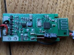
    I have this device (BL602 on magic home RGB, not exactly the device on picture) :
    Tasmota replacement for BL602, programming, pairing with Home Assistant, now with OTA working!

    I want use it to control LED of my fishtank (2 outputs required : 1 for Warm, 1 for Cold)

    According to the first post, I flash it with OpenBL602_1.15.204.bin

    I can connect it throw 192.168.169.1 AP IP adress and make my change (setting WIFI and output configuration).
    I can receive data throw MQTT (I can't yet control device, but that's not really the problem).

    My wish is to have a long time dimming. I don't know if I'm clear, so I will explain a bit more.
    Is it possible to set a "terminal value" and a "delay" ? When the command is sent, the PWM increase (or decrease) during the delay to point the terminal value.

    I don't find any information about that, so I think it's not a implemented function.

    So I try to make a script named (for exemple) "day" and put a loop with increasing variable and a test to stop the script.
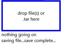
    But impossible to show the filesystem, impossible to add file (I give name of file, Firefow tell me "Will try to create day", I show :
    Tasmota replacement for BL602, programming, pairing with Home Assistant, now with OTA working!

    But impossible to list, show, open, modify the file. Buttons haven't any response.
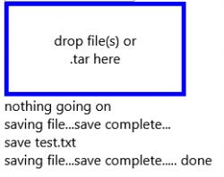
    I try to wrote a script under notepad and drop the file but nothing (name changes to text.txt) :
    Tasmota replacement for BL602, programming, pairing with Home Assistant, now with OTA working!

    So what's wrong ?

    Thanks for attention. Regards
  • #232 20347296
    rkarolek
    Level 10  
    Hi
    I bought a four-channel relay module, I didn`t actually notice that it wasn`t ESP enabled - and that`s how I found out about BL602 :)
    Has anyone uploaded the firmware from this thread to it?
    If so, can you share the configuration, i.e. which pin is responsible for what?
    link to my board https://pl.aliexpress.com/item/10050049800849...t_main.17.3c441c24DneLdn&gatewayAdapt=glo2pol
  • #233 20347309
    p.kaczmarek2
    Moderator Smart Home
    Show clear photos of the WiFi module and we will try to advise you. You need to find RX, TX and boot. Ultimately, you can guess the signals from buttons and relays once you upload the new firmware.
    Helpful post? Buy me a coffee.
  • #234 20347388
    rkarolek
    Level 10  
    Rx, txt, etc. are not a problem, they are nicely described on the module
    However, assigning pins to the relay etc. would make it easier and save a lot of time, which is not much time before Christmas.

    Tasmota replacement for BL602, programming, pairing with Home Assistant, now with OTA working!
    Tasmota replacement for BL602, programming, pairing with Home Assistant, now with OTA working!
  • #235 20347420
    p.kaczmarek2
    Moderator Smart Home
    To guess the relay pins, you set e.g. 8 relays (8 channels) on the pins in Configure Module, click the buttons on the HTTP panel and see if the relay responds. It doesn`t take that much. Then provide the configuration and I will place it on our devices page.

    Unless someone here already has this device - if so, please let me know.
    Helpful post? Buy me a coffee.
  • #236 20347460
    rkarolek
    Level 10  
    Ok, I`ll do that, and when I configure it, I`ll of course give you the info.
    I have one more question: is it possible to download and possibly restore the original firmware?
  • #237 20347477
    p.kaczmarek2
    Moderator Smart Home
    I don`t think I saw such an option in the manufacturer`s application - BLDevCube.exe. He just doesn`t share it.

    Maybe there is some other flashing tool that supports memory reading, but I don`t know anything about it. You`d have to look for it.

    Generally, there is very poor documentation and tools from the manufacturer.
    Helpful post? Buy me a coffee.
  • #238 20358071
    p.kaczmarek2
    Moderator Smart Home
    I looked into UART thing again and have some progress.

    davidcpurdy wrote:

    A few docs I looked at mention that UART0 ( tx=16, rx=7) is reserved for CLI and console. They used UART1 (tx=4, rx=3) for data transfer, as in this BL602 + E-Ink Display using UART.


    UART drivers will work now for UART0 by default. In order to avoid log conflicts, you must do:
    logtype none in short startup command (and reboot).
    So, for example, for BL0942 you need short startup command:
    backlog logtype none; startDriver BL0942
    Now the question is - which UART port is using your device? Do I need to add UART1 as well? For your device? If it's UART1 (tx=4, rx=3), then I will add an option to choose the port used by sensor.
    Helpful post? Buy me a coffee.
  • #239 20363791
    leifmjcb
    Level 3  
    Hi all, Happy new year!

    As my new years resolution, I've decided to stop pulling my hair out over these BL602 MagicHome LED controllers and come here for some help.

    I've flashed 6 of these now originally with 1.15.149 and today with 1.15.273.

    The config, operation, wifi & MQTT all seem to be working fine. I have no errors in logs.

    However I cant for the life of me get discovery to work. The only way I can connect via HA is by manually adding via YAML conf. But when I do this only an entity appears, no device.

    I am still learning HA and MQTT but I'm only having this problem with BL602, I've got many ESP and BK7231T devices working fine and with discovery.

    Here's my conf for this device:
    mqtt:
    light:
    - unique_id: "LED-UpstairsBedroom-BedLights_light"
    name: "LED_usbe_bed"
    rgb_command_template: "{{ '#%02x%02x%02x0000' | format(red, green, blue)}}"
    rgb_value_template: "{{ value[0:2]|int(base=16) }},{{ value[2:4]|int(base=16) }},{{ value[4:6]|int(base=16) }}"
    rgb_state_topic: "LED_usbe_bed/led_basecolor_rgb/get"
    rgb_command_topic: "cmnd/LED_usbe_bed/led_basecolor_rgb"
    command_topic: "cmnd/LED_usbe_bed/led_enableAll"
    state_topic: "LED_usbe_bed/led_enableAll/get"
    availability_topic: "LED_usbe_bed/connected"
    payload_on: "1"
    payload_off: "0"
    brightness_command_topic: "cmnd/LED_usbe_bed/led_dimmer"
    brightness_state_topic: "LED_usbe_bed/led_dimmer/get"
    brightness_scale: 100

    Apologies is this is a newbie question. But any help would be much appreciated.

    Screenshots attached

    Thanks!
    Leif Tasmota replacement for BL602, programming, pairing with Home Assistant, now with OTA working! Tasmota replacement for BL602, programming, pairing with Home Assistant, now with OTA working! Tasmota replacement for BL602, programming, pairing with Home Assistant, now with OTA working!
  • #240 20364820
    davidcpurdy
    Level 7  
    @p.kaczmarek2 , I hope you had a Good Christmas, and wish you a Happy and Prosperous New Year 2023...

    p.kaczmarek2 wrote:
    I looked into UART thing again and have some progress.
    ...
    UART drivers will work now for UART0 by default. In order to avoid log conflicts, you must do:
    logtype none in short startup command (and reboot).
    So, for example, for BL0942 you need short startup command:
    backlog logtype none; startDriver BL0942
    Now the question is - which UART port is using your device? Do I need to add UART1 as well? For your device? If it's UART1 (tx=4, rx=3), then I will add an option to choose the port used by sensor.


    I will flash this to a device tomorrow and report back on what behavior I see.

    Thank you, again.

Topic summary

The discussion centers on a custom Tasmota-like firmware replacement for the BL602 platform by Bouffalo Lab, enabling integration with Home Assistant via MQTT. Key topics include flashing the firmware using USB to UART converters, SDK compilation, and device pairing. Users report successful flashing on MagicHome LED controllers (RGB, RGBW, single color) and Sonoff devices, with detailed guidance on GPIO pin identification and configuration for PWM and relay functions. MQTT integration supports commands for color, dimmer, hue, saturation, and device control, with ongoing improvements to MQTT topic naming, discovery, and feedback reporting. Challenges addressed include MQTT buffer limitations causing device instability, startup behavior with LED blinking, and the absence of OTA updates for BL602 (unlike Beken platforms). The firmware supports saving and restoring channel states, configurable MQTT reporting flags, and plans for Alexa Hue emulation. Users share troubleshooting steps for flashing errors, network connectivity, and device crashes, with developer responses including bug fixes, feature additions, and testing requests. The project emphasizes open-source collaboration, aiming to free IoT devices from manufacturer servers, enhance privacy, and unify multi-vendor ecosystems under a single firmware solution.
Summary generated by the language model.
ADVERTISEMENT