Elektroda.com
Elektroda.com
X

[BK7231N ] Teardown of TH08 LCD Calendar/clock/temperature/humidity, 3xAAA battery, backlight

morgan_flint 3774 78
  • #61
    auntlydia
    Level 8  
    Hi, just quick update @morgan_flint , I have checked another of my devices of the same model, and can confirm that also here, the MCU chips U3 and U8 have no markings. Also, the battery discharge happens faster than expected, however I haven't tried with 3 same-level fully charged batteries. At some point I will put 3x AAA fully charged rechargeable batteries with 1.2V, and try how long it lasts under daily normal conditions, and probably will test with fresh 1.5V non-rechargeable batteries too. In case I do an USB direct power mod, I'll post here too.
  • #62
    morgan_flint
    Level 8  
    Thanks for the information, it's a pity we can't identify those chips, specifically U8 (I'm intrigued about it). I finally could repair my scope yesterday, so I'll take a new look at the communication between U3 and U8.

    Regarding battery discharging, let's see if @p.kaczmarek2 can take a look at the information in my previous post to see if the "closing message" that the WiFi module is sending to the MCU is adequate.
  • #63
    spin55
    Level 15  
    morgan_flint wrote:
    Is there any command in the Tuya protocol to change the polling time? If this is the case, we could try to see if it's implemented in the MCU's firmware


    This link to the Tuya protocol is for version 03 (devices that connect to the electrical grid), but in this case version 00 must be taken as a reference (Wifi for Low Power) https://developer.tuya.com/en/docs/iot/tuyacloudlowpoweruniversalserialaccessprotocol?id=K95afs9h4tjjh

    If you take a look at the two protocols you will see that they are different and, taking into account that p.kaczmarek2 has based its firmware on protocol 03, although it has adapted it when new battery-powered devices have emerged, it is not enough because some commands work differently in version 00. A Flag would be necessary for the firmware to know if it is a device with a battery or not, and based on that apply the correct command.

    From the documentation it seems that command 09 can help you know if this device has the necessary DP implemented.

    Send module command
    Note:
    
    “Send command” is an asynchronous processing protocol. When the MCU receives the control packet, it responds to the module about the reception and controls the device according to the command. The MCU status response is shown in the status reporting of the MCU.
    
    For example, the module sends the following command:
    
    Field	          Length (byte)	Description
    Header	                2	        0x55aa
    Version	                1	        0x00
    Command word	        1	        0x09
    Data length	        2	It depends on the type and number of the “command data unit”
    Data	                N	See the “Status data unit” section
    Checksum	        1	Start from the header, add up all the bytes, and then divide the sum by 256 to get the remainder
    
    The module sends the control command: (The system switch corresponds to DP 3, uses Boolean data type, and the value of 1 indicates power-on)
    
    55 aa 00 09 00 05 03 01 00 01 01 13
    
    Response from the MCU:
    
    Field	           Length (byte)	Description
    Header	                2	          0x55aa
    Version	                1	          0x00
    Command word	        1	          0x09
    Data length	        2	          0x0000
    Data	                0	          None
    Checksum	        1	Start from the header, add up all the bytes, and then divide the sum by 256 to get the remainder
    
    ACK response form the MCU:
    
    55 aa 03 09 00 00 0b


    Unless there is an error, the command to send would be: 55aa00090008110200040000000524 for a reporting interval of 5 minutes.

    And TuyaMCU should answer with: 55aa030900000b.

    If the MCU does not respond, it is not implemented.

    This can be tested with a USB adapter connected to the Tx and Rx lines of the WiFi module and monitored with Realterm if the module is already flashed with OpenBK. Do the test without the batteries.

    Grettings
  • #64
    spin55
    Level 15  
    morgan_flint wrote:
    Regarding battery discharging, let's see if @p.kaczmarek2 can take a look at the information in my previous post to see if the "closing message" that the WiFi module is sending to the MCU is adequate.


    It seems that the WiFi module receives a request Query the signal strength of the currently connected router (0B) and tries to respond with an incorrect command (08). And he does it three times in accordance with what is expressed in the protocol information:

    --------------------------------
    Note:

    All data greater than one byte shall be transmitted with big-endian mode.

    All examples in the protocol use hexadecimal data.

    The packets sent by Wi-Fi module time out after 1 second. The resend mechanism will resend three packets.

    Generally, the same command word adopts synchronous sending and receiving mechanism. One party sends a command, and the other party responds. If the sender fails to receive the correct response packet within the stipulated period, the transmission times out.
    --------------------------------

    But that would only be 3 seconds.
  • #65
    auntlydia
    Level 8  
    I have tested now with fully charged 1.2V AAA rechargeable batteries. After only 3 days the device was out of sufficient power and kept then rebooting every now and then, and in consequence lost its time setting. I suppose at some point the power is enough to supply the display and sensor, but not to establish a frequent WiFi connection. Have others similar results? I will test with the same batteries with original Tuya firmware and see if there is a difference. Compared to TH01 sensor, which lasts several weeks or even months with fresh batteries with openbk, this is a huge difference.
  • #66
    spin55
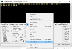
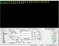
    Level 15  
    auntlydia wrote:
    I have tested now with fully charged 1.2V AAA rechargeable batteries. After only 3 days the device was out of sufficient power and kept then rebooting every now and then, and in consequence lost its time setting. I suppose at some point the power is enough to supply the display and sensor, but not to establish a frequent WiFi connection. Have others similar results? I will test with the same batteries with original Tuya firmware and see if there is a difference. Compared to TH01 sensor, which lasts several weeks or even months with fresh batteries with openbk, this is a huge difference.


    The problem of battery depletion seems to be related to the type of base technology, which is why Zigbee is much more efficient for battery-powered devices, because this type of module consumes much less in Tx mode than conventional WiFi.

    For devices that are permanently connected to the electrical grid there is no problem with consumption, regardless of the type of technology.

    Grettings
  • #67
    morgan_flint
    Level 8  
    morgan_flint wrote:
    I finally could repair my scope yesterday, so I'll take a new look at the communication between U3 and U8.

    Hello to all, after some time inactive, but I had been doing several experiments and suddenly the device stopped working... After reflashing OBK a couple of times with no success, I reflashed the original FW and all seems back to normal. I'll reflash OBK later again and see what happens.

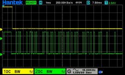
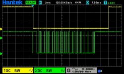
    Regarding communication between U3 and U8, my initial guess (pins 4 and 5 of U3 connected to pins 10 and 8 of U8 respectively being serial or I2C) proved incorrect. U3_5-U8_8 apparently never changed (always high) and U3_4-U8_10 was normally high and went low for about 20 mS repeating this every 2 seconds approximately. Of course, this didn't seem enough to program the (according to my guess) RTC from the MCU, so I decided to take a look at the pad labeled "Light_Signal" and, bingo! it looked like a serial communication.

    The following images show U8 pin 10 (yellow trace) and Light_Signal (green one). As you can see, the yellow trace goes down coinciding with the first or second low to high transition of the green one (if it was first or second seemed random), and went high again a few ms after the end of activity in the green one.
    [BK7231N ] Teardown of TH08 LCD Calendar/clock/temperature/humidity, 3xAAA battery, backlight [BK7231N ] Teardown of TH08 LCD Calendar/clock/temperature/humidity, 3xAAA battery, backlight

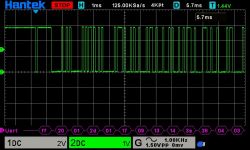
    I couldn't guess the utility of this signal (maybe an acknowledgment sent from U8 to U3 when it receives serial communication?) so I went on with the analysis of Light_Signal:
    [BK7231N ] Teardown of TH08 LCD Calendar/clock/temperature/humidity, 3xAAA battery, backlight

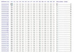
    I wasn't very confident about the protocol decoding of the scope, so I connected Light_Signal to a serial to USB converter and got this (the hex file is also attached):
    [BK7231N ] Teardown of TH08 LCD Calendar/clock/temperature/humidity, 3xAAA battery, backlight

    As you can see, it consists of a 16-byte array. The capture was done on power on, so the bunch of 00's at the beginning seem to be related to the period while the date and time hadn't yet been received from the NTP server. After some more captures and looking simultaneously at the display, I think:
    - The 1st byte is a header (always FF)
    - 2nd byte is related to the temperature
    - 3rd is always 01 (?)
    - 4th is related to the humidity
    - 5th is always 01 (?)
    - 6th to 11th to date-time, except for the 8th one that changed for a few seconds when the button was pressed (backlight)
    - I couldn't guess the meaning of the rest of the bytes

    It would be interesting to fully decode this protocol if we wanted to get rid of the Tuya MCU and control U8 directly from the module, but I don't think it's worth the effort...
  • #68
    morgan_flint
    Level 8  
    spin55 wrote:
    Unless there is an error, the command to send would be: 55aa00090008110200040000000524 for a reporting interval of 5 minutes.

    And TuyaMCU should answer with: 55aa030900000b.

    Hello, Spin55

    I tried this and, after a lot of trial and error, could send that stream with a tool called ComDebug and get the response from the MCU with Realterm. I had also tried sending it with realterm, but if I pasted 55AA00090008110200040000000524 to Realterm, it would change it to 35 35 41 41 30 30 30 39 30 30 30 38 31 31 30 32 30 30 30 34 30 30 30 30, and this was what was received in another terminal with its COM port's RX connected to the first one's TX. I tried several options in realterm but couldn't find any that permitted me to receive what I wanted to send, so I had to use ComDebug to send the sequence.

    Anyway, the MCU just answered FF FF to that sequence, so I guess that DP is not implemented.

    Added after 23 [minutes]:

    spin55 wrote:
    The problem of battery depletion seems to be related to the type of base technology, which is why Zigbee is much more efficient for battery-powered devices because this type of module consumes much less in Tx mode than conventional WiFi.

    I agree Zigbee would be more efficient, but I also think there's a problem with the terminating sequence sent by OBK to the MCU, as I said here, because with OBK the module remains connected for a long time each time it's powered on by the MCU (more than a minute) while with the original FW it goes off just after the communication with the MCU ends (about 10 seconds).

    I still have to test how long would a battery last with OBK and compare it to original FW, but measuring the consumption with the original FW it's about 0.03mA on standby, but it peaks to even more than 50 mA (25-30 mA on average) when the module is connected, so the difference of on-time between both FWs can make a significant difference on battery usage. Probably, it's due to the differences between version 03 and version 01 of the protocols as you said before.
  • #69
    spin55
    Level 15  
    morgan_flint wrote:
    I had also tried sending it with realterm, but if I pasted 55AA00090008110200040000000524 to Realterm


    Would you mind commenting on how you tried to send it with Realterm? If possible with Realterm images.
  • #70
    morgan_flint
    Level 8  
    Copied the sequence from your post (55AA00090008110200040000000524) with Ctrl+C and pasted it into the realterm screen (Ctrl+Alt+v or right click + "paste to port").
    [BK7231N ] Teardown of TH08 LCD Calendar/clock/temperature/humidity, 3xAAA battery, backlight

    The first image is selecting Hex in "Display as" and the second with Ascii. The receiving terminal (on the right) receives the same:
    [BK7231N ] Teardown of TH08 LCD Calendar/clock/temperature/humidity, 3xAAA battery, backlight
    [BK7231N ] Teardown of TH08 LCD Calendar/clock/temperature/humidity, 3xAAA battery, backlight

    There must be an option to indicate that you are pasting Hex, not Ascii, but I couldn't find it
  • #71
    spin55
    Level 15  
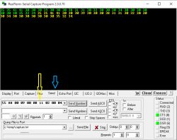
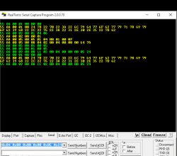
    I just confirmed the doubt I had. You have sent the command by doing a Copy/Paste in Send Number and you got what you see above. It is not correct, to send it you have to enter it by typing as seen in the image.

    In any case, it is no longer important because you could have done it with the other program and there is no DP17 implemented as you suspected.

    [BK7231N ] Teardown of TH08 LCD Calendar/clock/temperature/humidity, 3xAAA battery, backlight [BK7231N ] Teardown of TH08 LCD Calendar/clock/temperature/humidity, 3xAAA battery, backlight

    You have to send it from the Send tab.
  • #72
    morgan_flint
    Level 8  
    morgan_flint wrote:
    I agree Zigbee would be more efficient, but I also think there's a problem with the terminating sequence sent by OBK to the MCU, as I said here, because with OBK the module remains connected for a long time each time it's powered on by the MCU (more than a minute) while with the original FW it goes off just after the communication with the MCU ends (about 10 seconds).

    I've updated the comparison between the captures adding the relative timestamp (time from the first message) and there's something curious: As you can see, with the original FW the module answers to the first message from the MCU within 1 second, while OBK takes 10 seconds to answer.

    I also have looked WiFi for low power protocol for the last message sent to the module (55AA000B00000A) and it's response (55AA000B000201505D). The first one is "MCU obtains the strength of the connected router" (I understand the MCU asks the module for the signal strength) and the response from the module is "Module returns current value of strength (80)". None of these seem to have any meaning in the "normal" protocol, nor could I find the meaning of the last answer (repeated three times) of the module with the OBK FW (55AA000800010008), being this one the more similar one (55 aa 00 08 00 00 07, Query DP status).

    So, probably, the MCU is waiting for the strength signal data and receives instead a query it doesn't understand, so remains a long time waiting for the answer without disconnecting the module, until it finally gives up
  • #73
    morgan_flint
    Level 8  
    >>20747082
    I had tried also that, but if I hit "send numbers" nothing happens, and if I hit "send ascii" I get the same result as of pasting directly to the terminal...

    I must have something wrong with my configuration
  • #74
    spin55
    Level 15  
    morgan_flint wrote:
    I also have looked WiFi for low power protocol for the last message sent to the module (55AA000B00000A) and it's response (55AA000B000201505D). The first one is "MCU obtains the strength of the connected router" (I understand the MCU asks the module for the signal strength) and the response from the module is "Module returns current value of strength (80)". None of these seem to have any meaning in the "normal" protocol, nor could I find the meaning of the last answer (repeated three times) of the module with the OBK FW (55AA000800010008), being this one the more similar one (55 aa 00 08 00 00 07, Query DP status).

    So, probably, the MCU is waiting for the strength signal data and receives instead a query it doesn't understand, so remains a long time waiting for the answer without disconnecting the module, until it finally gives up


    Now you have understood it.

    Added after 4 [minutes]:

    morgan_flint wrote:
    I had tried also that, but if I hit "send numbers" nothing happens, and if I hit "send ascii" I get the same result as of pasting directly to the terminal...

    I must have something wrong with my configuration


    Como conectas UART Usb con placa??

    Conectas Tx y Rx de USB a Tx y Rx de módulo WiFi??.

    Although it may seem strange, it is better to connect from the WiFi module than directly to the Tx and Rx pins of the TuyaMCU chip to take advantage of the resistances that should be between terminals to avoid possible short circuits.
  • #76
    spin55
    Level 15  
    @morgan_flint:

    I forgot to tell you that to prevent the WiFi module from interfering with the USB connection when you want to carry out the test with batteries inserted, you have to set the CEN pin of the module to GND.

    Back in the day I communicated with the TuyaMCU chip both without batteries and with them, as you can read in this link: https://www.elektroda.com/rtvforum/topic3937723-90.html
  • #77
    morgan_flint
    Level 8  
    spin55 wrote:
    Como conectas UART Usb con placa??

    Conectas Tx y Rx de USB a Tx y Rx de módulo WiFi??.

    For that test with Realterm I wasn't using the TH08, just two serial to USB with TX of one connected to RX of the other, just to check what I'm sending from the first one. When I saw I wasn't sending the correct sequence, then I switched to ComDebug to make the test sending the sequence to the MCU.

    spin55 wrote:
    I forgot to tell you that to prevent the WiFi module from interfering with the USB connection when you want to carry out the test with batteries inserted, you have to set the CEN pin of the module to GND.


    To be sure, in my tests I fully isolated module and MCU, cutting RX, TX and CEN, but that is a simpler method, I'll use it in future tests

    Added after 19 [minutes]:

    p.kaczmarek2 wrote:
    So it seems that we have to send one extra packet to get sleep earlier?

    I think the best possibility would be to implement the correct response to the query from MCU to module 55AA000B00000A (MCU obtains the strength of the connected router) that the module should respond with 55AA000B000201505D (Module returns current value of strength (80)), ideally adapting the latter to the real signal strength, according to the protocol described here (55AA000B0002XXYYZZ, being XX failure/success, YY the strength in hex and zz the chechsum). If it's complicated to implement the real signal strength, just sending a fixed value is enough, probably the MCU just uses this info to show it in the WiFi symbol on the screen.

    I haven't been able to find the meaning of the last three messages that the MCU is receiving (55AA000800010008 repeated three times), but the original FW doesn't send them so, if possible, they should be omitted.
  • #78
    spin55
    Level 15  
    @morgan_flint,

    First of all, I apologize because the information I provided you about using Realterm is not correct, because a few months have passed since I used the program and I answered you based on what I remembered.

    I reconnected the USB adapter to the pir motion NEO and realized the error.

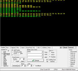
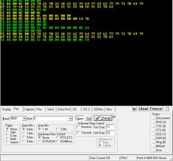
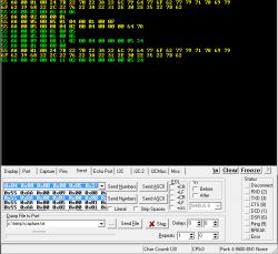
    This is how you have to configure Realterm:

    Display tab:

    [BK7231N ] Teardown of TH08 LCD Calendar/clock/temperature/humidity, 3xAAA battery, backlight

    Port tab:

    [BK7231N ] Teardown of TH08 LCD Calendar/clock/temperature/humidity, 3xAAA battery, backlight

    Send tab:

    [BK7231N ] Teardown of TH08 LCD Calendar/clock/temperature/humidity, 3xAAA battery, backlight [BK7231N ] Teardown of TH08 LCD Calendar/clock/temperature/humidity, 3xAAA battery, backlight

    As you can see, the data must be entered in hexadecimal format.
    You add them one at a time and press Send Number. To enter the following ones you can edit the one you just entered and so on. When you connect the device you choose them from the drop-down tab.

    On the screen you will see the commands you send in green and the responses from TuyaMCU in yellow.

    As you can see, I sent commands 01 and 02 that were answered by MCU with the identification data (01), acknowledgment that there is already a connection to the cloud (02) and the status of the variables (05). In this case the detection values ​​(00) and battery level (64) which in decimal is 100 as you already know.
    And you can also see that I sent command 09 and it hasn't responded.

    This test is done with the connections as I mentioned in a previous post and without battery or external power. Tx, Rx, GND from USB to Tx, Rx, GND from Wifi module and CEN to GND.
  • #79
    morgan_flint
    Level 8  
    Thank you for the info, @spin55
    I made the experiments again with this configuration and could effectively send the message by writing the hex numbers as 0xXX, so I made a first test sending from Realterm the first packet in the sniffed logs and obtaining the same answer from the MCU. Then tried sending the message from your post here:
    spin55 wrote:
    Unless there is an error, the command to send would be: 55aa00090008110200040000000524 for a reporting interval of 5 minutes.

    And TuyaMCU should answer with: 55aa030900000b.


    With no response from the MCU, so definitively this is not implemented.

    So now let's see if @p.kaczmarek2 can implement the correct response to the last query from the MCU to the module MCU obtains the strength of the connected router (55AA000B00000A) and see if this abbreviates the time before the MCU powers off the module (details at the end of this post).

    Another thing that would be interesting to investigate is why with the original FW the module answers to the first message from the MCU within 1 second, while OBK takes 10 seconds to answer, as I said at the beginning of this post. I'll try it again when I reflash OBK to confirm this delay.