logo elektroda
logo elektroda
X
logo elektroda

[BK7231N ] Teardown of TH08 LCD Calendar/clock/temperature/humidity, 3xAAA battery, backlight

morgan_flint 29802 225
ADVERTISEMENT
  • #121 20893731
    p.kaczmarek2
    Moderator Smart Home
    Maybe wrong TuyaMCU baud rate?
    Are there ANY TuyaMCU packets in the Web App Log?
    Try adding:
    
    tuyaMcu_setBaudRate 115200
    

    If not, then maybe try:
    
    // set TuyaMCU default wifi state 0x04, which means "paired",
    // because some TuyaMCU MCUs will not report all data
    // unless they think they are connected to cloud
    tuyaMcu_defWiFiState 4
    
    Helpful post? Buy me a coffee.
  • ADVERTISEMENT
  • #122 20893780
    vikicha
    Level 3  
    I try both settings but still no change.
    I can't see any TuyaMCU packet in WebApp Log.
    This is few secconds log after boot with both setting you sugest in autoexdec.bat

    o:MAIN:Main_Init_Delay done
    Info:MAIN:Main_Init_After_Delay
    Info:MAIN:Using SSID [Lazarovi1]
    Info:MAIN:Using Pass [LazaroviDimitrovi]
    Info:MQTT:MQTT_RegisterCallback called for bT obkB9F79399/ subT obkB9F79399/+/set
    Info:MQTT:MQTT_RegisterCallback called for bT bekens_n/ subT bekens_n/+/set
    Info:MQTT:MQTT_RegisterCallback called for bT cmnd/obkB9F79399/ subT cmnd/obkB9F79399/+
    Info:MQTT:MQTT_RegisterCallback called for bT cmnd/bekens_n/ subT cmnd/bekens_n/+
    Info:MQTT:MQTT_RegisterCallback called for bT obkB9F79399/ subT obkB9F79399/+/get
    Info:CMD:CMD TCP server started!
    Info:CMD:CMD_StartScript: started autoexec.bat at the beginning
    Info:MAIN:Main_Init_After_Delay done
    Info:NTP:NTP driver initialized with server=162.159.200.1, offset=0
    Info:MAIN:Started NTP.
    Info:MAIN:Started TuyaMCU.
    Info:MAIN:Started tmSensor.
    Info:NTP:NTP server set to 162.159.200.1
    Info:NTP:NTP offset set
    Info:GEN:Channel 1 type changed to temperature_div10
    Info:GEN:Channel 2 type changed to Humidity
    Info:GEN:Channel 3 type changed to ReadOnlyLowMidHigh
    Info:MAIN:Time 1, idle 264547/s, free 75792, MQTT 0(0), bWifi 0, secondsWithNoPing -1, socks 3/38 
    Info:MAIN:Time 2, idle 189916/s, free 75792, MQTT 0(0), bWifi 0, secondsWithNoPing -1, socks 3/38 
    Info:MAIN:Time 3, idle 190216/s, free 75792, MQTT 0(0), bWifi 0, secondsWithNoPing -1, socks 3/38 
    Info:MAIN:Time 4, idle 189001/s, free 75792, MQTT 0(0), bWifi 0, secondsWithNoPing -1, socks 3/38 
    Info:MAIN:Time 5, idle 190120/s, free 75792, MQTT 0(0), bWifi 0, secondsWithNoPing -1, socks 3/38 
    Info:MAIN:ssid:Lazarovi1 key:LazaroviDimitrovi
    Info:MAIN:Time 6, idle 182004/s, free 70496, MQTT 0(0), bWifi 0, secondsWithNoPing -1, socks 3/38 
    Info:MAIN:Boot complete time reached (5 seconds)
    Info:CFG:####### Set Boot Complete #######
    Info:MAIN:Time 7, idle 181486/s, free 70504, MQTT 0(0), bWifi 0, secondsWithNoPing -1, socks 3/38 
    Info:MAIN:Time 8, idle 83108/s, free 70808, MQTT 0(0), bWifi 0, secondsWithNoPing -1, socks 3/38 
    Info:MAIN:Time 9, idle 0/s, free 70808, MQTT 0(0), bWifi 0, secondsWithNoPing -1, socks 3/38 
    Info:MAIN:Time 10, idle 0/s, free 70808, MQTT 0(0), bWifi 0, secondsWithNoPing -1, socks 3/38 
    Info:GEN:dhcp=0 ip=0.0.0.0 gate=0.0.0.0 mask=0.0.0.0 mac=50:8b:b9:f7:93:99
    Info:GEN:sta: 0, softap: 0, b/g/n
    Info:MAIN:Main_OnWiFiStatusChange - WIFI_STA_CONNECTING - 1
    Info:MAIN:Time 11, idle 108972/s, free 69288, MQTT 0(0), bWifi 0, secondsWithNoPing -1, socks 3/38 
    Info:MAIN:Main_OnWiFiStatusChange - WIFI_STA_DISCONNECTED - 2
    Info:MAIN:Time 12, idle 187107/s, free 71120, MQTT 0(0), bWifi 0, secondsWithNoPing -1, socks 3/38 
    Info:MAIN:Time 13, idle 188629/s, free 71120, MQTT 0(0), bWifi 0, secondsWithNoPing -1, socks 3/38 
    Info:MAIN:Time 14, idle 190005/s, free 71120, MQTT 0(0), bWifi 0, secondsWithNoPing -1, socks 3/38 
    Info:MAIN:Time 15, idle 187268/s, free 71120, MQTT 0(0), bWifi 0, secondsWithNoPing -1, socks 3/38 
    Info:MAIN:Time 16, idle 189962/s, free 71120, MQTT 0(0), bWifi 0, secondsWithNoPing -1, socks 3/38 
    Info:MAIN:Time 17, idle 189981/s, free 71120, MQTT 0(0), bWifi 0, secondsWithNoPing -1, socks 3/38 
    Info:MAIN:Time 18, idle 188855/s, free 71120, MQTT 0(0), bWifi 0, secondsWithNoPing -1, socks 3/38 
    Info:MAIN:Time 19, idle 188751/s, free 71120, MQTT 0(0), bWifi 0, secondsWithNoPing -1, socks 3/38 
    Info:MAIN:Time 20, idle 189956/s, free 71120, MQTT 0(0), bWifi 0, secondsWithNoPing -1, socks 3/38 
    Info:GEN:dhcp=0 ip=0.0.0.0 gate=0.0.0.0 mask=0.0.0.0 mac=50:8b:b9:f7:93:99
    Info:GEN:sta: 0, softap: 0, b/g/n
    Info:MAIN:Main_OnWiFiStatusChange - WIFI_STA_AUTH_FAILED - 3
    Info:MAIN:Time 21, idle 191339/s, free 70424, MQTT 0(0), bWifi 0, secondsWithNoPing -1, socks 3/38 
    Info:MAIN:Time 22, idle 186418/s, free 69896, MQTT 0(0), bWifi 0, secondsWithNoPing -1, socks 3/38 
    Info:MAIN:Main_OnWiFiStatusChange - WIFI_STA_CONNECTING - 1
    Info:MAIN:Time 23, idle 185882/s, free 68672, MQTT 0(0), bWifi 0, secondsWithNoPing -1, socks 3/38 
    Info:MAIN:Main_OnWiFiStatusChange - WIFI_STA_CONNECTED - 4
    Info:MAIN:Main_OnWiFiStatusChange - WIFI_STA_CONNECTED - 4
    Info:MAIN:Time 24, idle 176729/s, free 70808, MQTT 0(0), bWifi 1, secondsWithNoPing -1, socks 4/38 
    Info:NTP:Seconds since Jan 1 1900 = 3913522337
    Info:NTP:Unix time  : 1704537137
    Info:NTP:Local Time : 2024/01/06 10:32:17
    Info:MAIN:Time 25, idle 189705/s, free 71048, MQTT 0(0), bWifi 1, secondsWithNoPing -1, socks 3/38 
    Info:MQTT:mqtt_host empty, not starting mqtt
    Info:MAIN:Time 26, idle 189168/s, free 71048, MQTT 0(1), bWifi 1, secondsWithNoPing -1, socks 3/38 
    Info:MAIN:Time 27, idle 188556/s, free 71048, MQTT 0(1), bWifi 1, secondsWithNoPing -1, socks 3/38 
    Info:MAIN:Time 28, idle 189802/s, free 71048, MQTT 0(1), bWifi 1, secondsWithNoPing -1, socks 3/38 
    Info:MAIN:Time 29, idle 192883/s, free 71048, MQTT 0(1), bWifi 1, secondsWithNoPing -1, socks 3/38 
    Info:MAIN:Time 30, idle 190922/s, free 71048, MQTT 0(1), bWifi 1, secondsWithNoPing -1, socks 3/38 
    Info:GEN:dhcp=0 ip=192.168.1.28 gate=192.168.1.1 mask=255.255.255.0 mac=50:8b:b9:f7:93:99
    Info:GEN:sta: 1, softap: 0, b/g/n
    Info:GEN:sta:rssi=-58,ssid=Lazarovi1,bssid=c0:c9:e3:1b:e8:9e,channel=6,cipher_type:Error
    Info:MAIN:Time 31, idle 189374/s, free 70832, MQTT 0(1), bWifi 1, secondsWithNoPing -1, socks 4/38 
    Info:MAIN:Time 32, idle 190364/s, free 71048, MQTT 0(1), bWifi 1, secondsWithNoPing -1, socks 3/38 
    Info:MAIN:Time 33, idle 189787/s, free 71048, MQTT 0(1), bWifi 1, secondsWithNoPing -1, socks 3/38 
    Info:MAIN:Time 34, idle 191882/s, free 71048, MQTT 0(1), bWifi 1, secondsWithNoPing -1, socks 3/38
  • ADVERTISEMENT
  • #123 20893794
    p.kaczmarek2
    Moderator Smart Home
    So you have no TuyaMCU packets with both:
    
    tuyaMcu_setBaudRate 115200
    

    present and with it removed? Make sure to save and reboot after each change.

    But wait, how are you powering your WiFi module? You will NOT get any packets if you artificially power the module.

    Can you do Tuya config extraction so we can check the baud (for the extraction time, please do power module externally)
    Helpful post? Buy me a coffee.
  • ADVERTISEMENT
  • #124 20893860
    vikicha
    Level 3  
    Thanks a lot for your help and sugestions.
    What i had to do is to remove
    tuyaMcu_setBaudRate 115200
    and to add
    tuyaMcu_defWiFiState 4
    Also i forgot to remove artificial power from WiFi module, this was only way to force it to connect and make changes on configuration.
    Now it sends Temp and Humidity also gets correct Date and time.

    Is there a way to force WiFi not go in to sleep state and to be always powered on? I plan to use it with external adaptor so power consumption is not a problem.
  • #125 20893994
    morgan_flint
    Level 14  
    auntlydia wrote:
    The problem that a sensor shows zero values happened to me when I forced the device in keeping wifi connection by keeping the button pressed

    Same to me; maybe this "forced" state is only for FW updating and the TuyaMCU stops doing anything to avoid interfering. Also, as the wifi interface is off most of the time to save batteries, is difficult to consult the sensors through the OBK web page. But the reporting to Home Assistant works well always.

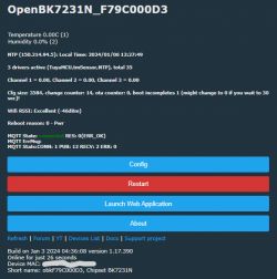
    This is a screenshot during "forced" mode:
    Screenshot of the OpenBK7231N interface in forced mode displaying data and options.

    This is my autoexec.bat:
    Code: Javascript
    Log in, to see the code

    vikicha wrote:
    Also i try to flash it on PCB directly but it did not work, i have to desolder it and then the flash is successful.

    I had to cut the RX and TX lines between module and MCU for flashing, and, if powering it from the battery terminals, also bypassing the transistor that controls the power of the module by cutting the GND (Q1). Probably it would be enough to cut/isolate RX. This was because, even feeding the module directly, the MCU would start working, as it received power from the RX/TX lines (see explanation here).

    As it seems like the TuyaMCU stops sending info in "forced" mode, this could be a possibility to avoid cutting RX and TX for flashing... I might give it a try but if someone else does, please report.

    vikicha wrote:
    Is there a way to force WiFi not go in to sleep state and to be always powered on? I plan to use it with external adaptor so power consumption is not a problem.

    Bypassing the aforementioned transistor would work (or simply connecting a wire from the module's GND to the main GND), but the TuyaMCU would still decide when to send the sensor's info (changing this would require modifying its FW, almost impossible to do as we don't even know which MCU is it).

    I'll take also the opportunity to say that the battery level is still medium after two months (although during "forced" mode it goes to "low" after a while, due to the module's power consumption), so pretty good performance in this sense.
  • #126 20918829
    spupetic
    Level 3  
    Hello everyone!

    Did you have success with the forced mode? Unfortunately, the Tuya MCU interferes with the CBU, and I cannot flash it with OpenBK, writing stops at approximately 70 percent, and pushing the button does not help either. The module is directly powered. I think this issue takes place when the first flash is unsuccessful somewhy (in my case, instable connection), and the device is not running the original firmware anymore.
  • #127 20918837
    p.kaczmarek2
    Moderator Smart Home
    I am always just desoldering WiFi module or cutting trace to the MCU for the time of the flashing.
    Helpful post? Buy me a coffee.
  • #128 20918966
    morgan_flint
    Level 14  
    spupetic wrote:
    Did you have success with the forced mode? Unfortunately, the Tuya MCU interferes with the CBU, and I cannot flash it with OpenBK, writing stops at approximately 70 percent, and pushing the button does not help either

    Hello!
    I did some experiments yesterday, and it seems you have to cut also the CEN signal, as the TuyaMCU also controls it and puts it in a low state periodically. Probably, this is what makes flashing stop after some time, something that also happened to me.

    BTW, after these experiments, my module stopped connecting to WiFi :-(; maybe something got corrupted due to one of these interrupted flashings. Will "Erase all" and/or "Restore RF part" in advanced options of BK7231Flasher help with this? I see in the contextual help that "Restore RF part" flashes a random MAC. Is there an option to flash the original MAC again?

    Another last question: What is "Allow backup restore" advanced option for?
  • #129 20919020
    p.kaczmarek2
    Moderator Smart Home
    morgan_flint wrote:

    I did some experiments yesterday, and it seems you have to cut also the CEN signal, as the TuyaMCU also controls it and puts it in a low state periodically. Probably, this is what makes flashing stop after some time, something that also happened to me

    That's a new to me, thank you for sharing it.


    morgan_flint wrote:

    BTW, after these experiments, my module stopped connecting to WiFi :-(; maybe something got corrupted due to one of these interrupted flashings. Will "Erase all" and/or "Restore RF part" in advanced options of BK7231Flasher help with this? I see in the contextual help that "Restore RF part" flashes a random MAC. Is there an option to flash the original MAC again?

    First try just Safe Mode (5 quick power off/on), then maybe try restore RF (you can change back MAC to original in the OBK UI), then erase all... but it's still strange, maybe first check TX2 output to see what crashes?

    morgan_flint wrote:

    Another last question: What is "Allow backup restore" advanced option for?

    Checking this option will show firmware backups in the combobox for selecting target firmware to flash, so you can, just as it says, restore the backup
    Helpful post? Buy me a coffee.
  • #130 20919613
    morgan_flint
    Level 14  
    p.kaczmarek2 wrote:
    First try just Safe Mode (5 quick power off/on)

    I had tried yesterday with no luck, but tried again today and could restore everything. Thanks!

    morgan_flint wrote:
    vikicha wrote:
    Is there a way to force WiFi not go in to sleep state and to be always powered on? I plan to use it with external adaptor so power consumption is not a problem.

    Bypassing the aforementioned transistor would work (or simply connecting a wire from the module's GND to the main GND)

    I tried this again and seems to work OK. The values of the sensors also show correct values in the OBK's main web page.

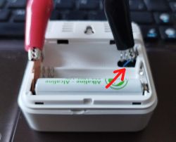
    I soldered a thin wire to the module's GND and brought it out through the same hole as the negative battery terminal, so I can connect or disconnect it to main GND without opening the case:
    View of the inside of a casing with an alkaline battery and a thin wire soldered to the module.
  • #131 20920621
    morgan_flint
    Level 14  
    I've just read this in the Tuya's developer website:
    For the MCU that can control the on/off of the module, its TX and RX are idle high in most hardware designs. Therefore, the TX and RX on the MCU are generally configured as push-pull output and input respectively. This will cause the TX and RX to output a low current. When the module is disconnected from the VCC, it cannot be powered off completely due to the low current from the TX and RX on the MCU. This might cause some problems with hardware operation. To resolve the current sink problem without modifying the circuit, in MCU programming, you can disable the serial port when the module is powered off. Configure the TX and RX either as an open-drain output in high impedance or as a low level. If the TX or RX is connected to a pull-up resistor, it must be configured as low level.

    As you can see, it addresses the problem of feeding something (the module in this case) through the serial port, a topic that I've seen commented on in other threads (and in this eevblog's video).

    This made me think of the way this device controls power to the module, with Q1 cutting GND, instead of Vcc, as per Tuya's recommended design (for example, here. Cutting GND instead of Vcc avoids the module being (partially) fed from the serial port, as GND is also the return path for this port, so disconnecting it seems a good idea, as it avoids the need of taking it into account in the software.

    What do you think?
  • #132 20927855
    spupetic
    Level 3  
    Can you show me where did you cut the traces, and how you connected them back after flashing?
  • #133 20929216
    p.kaczmarek2
    Moderator Smart Home
    That's a good find, @morgan_flint
    @spupetic how does your PCB look like? You can connect them back by
    1. first, scrap the solder mask from both ends of the cut trace
    2. then, add some solder on it (tin it)
    3. then place a short cut lead of, for example, axial resistor, and solder it on trace
    Helpful post? Buy me a coffee.
  • #134 20929625
    morgan_flint
    Level 14  
    spupetic wrote:
    Can you show me where did you cut the traces, and how you connected them back after flashing?

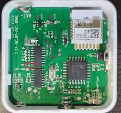
    The TX and RX lines can be cut where I'm showing in this picture, anywherein the track connecting pins 9 and 10 to RX1 and TX1 test pads (where, by the way, I soldered the wires for flashing), leaving enough space between them and with the rest of components so it's easy to reconnect them with a thin wire after flashing in the way @p.kaczmarek2 said:
    Close-up of a circuit board with markings and TX and RX signal wires.

    I don't think it's necessary to cut the one that goes to TX1, as this is a signal that comes from the module to the MCU, so the MCU can't interfere.

    As for the CEN signal, it's connected to pin 8, and goes below the IC and probably through the other face of the PCB so, in this case, I preferred to lift slightly the pin and isolate it from the PCB, You can do this by heating it with the soldering iron and pushing it up carefully at the same time with a thin blade.
  • #135 20929671
    p.kaczmarek2
    Moderator Smart Home
    I think there is also a possibility to cut the trace before the TX1/RX1 pad and then just reuse the pad to solder jumper wire directly to CBU. It may be easier to solder to the solder pad and CBU pad than to reconstruct the trace.
    Helpful post? Buy me a coffee.
  • ADVERTISEMENT
  • #136 20945212
    spupetic
    Level 3  
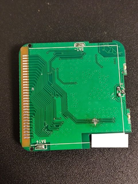
    Thank you for the information. I have a newer board revision, the CEN, RX and TX are on the other side of the PCB. I did not managed to connect them back without shorting to ground (probably cut too deep and far from the trace), so I used wires to make it work again.

    Close-up of a green printed circuit board with visible traces and gold contacts on the left side. Close-up of a circuit board with attached red wires.
  • #137 20947613
    morgan_flint
    Level 14  
    Wow! Completely different board!

    They seem to have combined the functions of two ICs in the previous version (U3-MCU and U8-RTC) into one (U3, maybe MCU with RTC).

    U1 is also different between the two versions but seems to have the same function (LCD controller).

    They also seem to have included a switched mode regulator (L1 and surrounding components), while the previous version had only linear regulators, probably to extend battery life.

    Did it work well with OBK + configuration for the previous version?
  • #138 20947665
    spupetic
    Level 3  
    Yeah, the configuration seems to work fine. The MCU has no label sadly, so we don't know what it is. I have used it with NiMH batteries, they have lasted 1,5 week or so, now I am testing it with a different set of batteries. The CBU is in deep sleep. When I replaced the battery, OpenBeken was in safe mode, because it had like a 1000+ unsuccessful boot (probably when the battery voltage dropped to a certain level). I fixed it by connecting to the OpenBK AP and clicking exit safe mode, it is tricky because of the short period for Wi-Fi connection, but it can be done.
  • #139 20948309
    morgan_flint
    Level 14  
    Now that you mention deep sleep, I see that the transistor that cut the GND signal in my version (Q1 in the last photo I posted) has disappeared in this version and that there are two 2.8V test points, one labeled "MCU_2V8" and another one "CBU_2V8". CBU's GND seems to be directly connected to main GND and CBU's Vcc seems to come from the switched mode regulator:
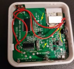
    PCB with visible traces, components, and red wires with connections.

    I guess that MCU power control by the MCU (if it really exists now) is done by controlling the enable pin of the switched mode regulator. If you find some mode of pulling up (or down) this signal then you can force the CBU to be on more time so connecting to it's AP (or flashing OTA) is easier. But, previously, you'd have to confirm what I guessed from the photo.
  • #141 20961998
    p.kaczmarek2
    Moderator Smart Home
    divadiow wrote:

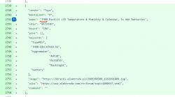
    TH08 should be in model field I guess:
    JSON code snippet describing an electronic product.
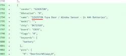
    Another little technical note (I know many people do that and I may done that in the past as well, but...):
    JSON code snippet with information about a door/window sensor.
    There is no need to repeat vendor from "vendor" field in the name, as the script will automatically display it anyway.
    Helpful post? Buy me a coffee.
  • #143 20988153
    fjcns
    Level 5  
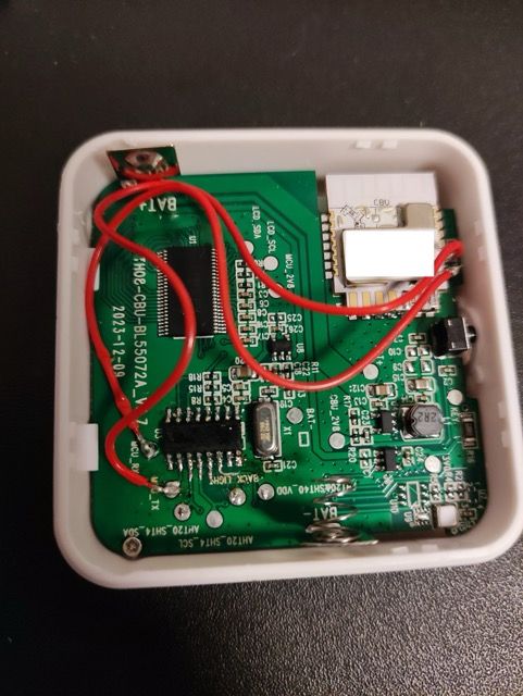
    Close-up of the interior of an electronic device with connected wires.
    Hello. I have a 2022-12-06 version of this device connected directly to a USB charger.

    I was able to flash the device, set the date, time and connect it to the homeassistant via mqtt.
    The temperature and humidity values ​​that appear on the screen update normally but are only updated in the web interface and sent by mqtt only once, when I turn on the device.

    In the web interface the internal temperature and dBm wi-fi signal are updated but the ambient temperature and humidity never update, even waiting for several hours.

    I try
    mqtt_broadcastItemsPerSec 20
    Try add/ remove flags
    without changes

    Does anyone have an idea of what might be wrong?
  • #144 20988432
    p.kaczmarek2
    Moderator Smart Home
    I think that it may not be possible to use battery powered Tuya device with a power connected constantly to the WiFi module because the MCU needs to be able to turn on and off the WiFi module and after each boot the MCU expects the WiFi module to begin the transaction. If the WiFi module is powered on all the time, then the WiFi module is not able to tell when to begin the transaction and the whole deal fails.

    Still, you can try to send the tuyaMcu_sendQueryState command.

    Or maybe you've got wrong dpID set? What does the log say?
    Helpful post? Buy me a coffee.
  • #145 20988482
    fjcns
    Level 5  
    with the original firmware the device was always powered by USB and worked normally.
    It was integrated into the Home Assistant with a some local Tuya integration that I'm not sure what it was anymore.

    try the command tuyaMcu_sendQueryState several times, results are

    Info:CMD:[WebApp Cmd 'tuyaMcu_sendQueryState' Result] OK

    one time report this error
    Error:CMD:cmd Info:CMD:[WebApp NOT found (args Cmd 'tuyaMcu_sendQueryState' Result] OK)
    Info:CMD:[WebApp Cmd 'Info:CMD:[WebApp Cmd 'tuyaMcu_sendQueryState' Result] OK' Result] Unknown command

    without change in update temperature


    log
  • #146 20988986
    Angel0fDeath
    Level 13  
    Quote:
    In the web interface the internal temperature and dBm wi-fi signal are updated but the ambient temperature and humidity never update, even waiting for several hours.


    @fjcns I have different temp/humidity device, but I noticed channels are updated via mqqt only if there is a change.
    So, you can try to add to your autoexec.bat
    addRepeatingEvent sec -1 backlog publishChannel X; publishChannel Y

    sec - publishing interval in seconds
    X - channel number humidity
    Y - channel number temp
    This will force publishing of these channels each [sec] stated in autoexec.bat.

    Please send some feedback

    EDIT: By me it is from TUYA MCU (should not be mistaken with tuya MCU driver). Just MCU reports when there are changes, otherwise - no report

    EDIT1: @p.kaczmarek2 tuyaMcu_sendQueryState works (according to logs), but there is still no publishing of the channel via MQTT if there is no change. The only way I have done it, is due to publishchannel each X seconds.
  • #147 20989131
    fjcns
    Level 5  
    I was measuring and the CBU module is always powered on.
    I cut the trace for vcc to CBU and ad a switch to turn the CBU module on and off manually.
    The module worked as expected
    I must have burned the Q1 mosfet while trying to inject power just into the CBU to flash the firmware.

    Thank you for your help and for sharing your knowledge
  • #148 20992155
    bogovik
    Level 5  
    Tuya WiFi Temperature & Humidity Sensor TH08B

    Link

    This is the temperature and humidity sensor of the new version of TH08B. I'm going to install a new firmware on it. I think it is fully compatible with the TH08 sensor.
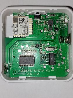
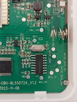
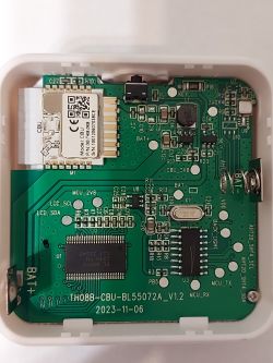
    TH08B-CBU-BL55072A_v1.2 2023-11-06

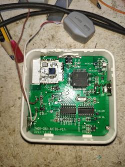
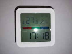
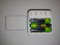
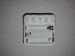
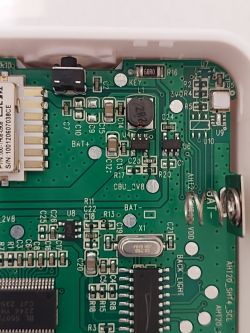
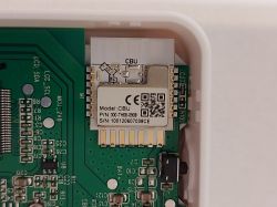
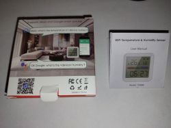
    Temperature and humidity sensor with display showing 27.9°C and 21% humidity. White temperature and humidity sensor on a gray background. Side view of a white temperature and humidity sensor. Open back of a sensor with three AA batteries. Back panel of TH08B sensor with open battery compartment Interior of the TH08B temperature and humidity sensor with visible electronic components and a circuit board. Close-up of the interior of the Tuya WiFi TH08B temperature and humidity sensor showing the circuit board. Close-up of electronic components on the circuit board of a sensor. Circuit board of Tuya WiFi temperature and humidity sensor TH08B Close-up of a circuit board with the CBU module of the TH08B sensor. Packaging and user manual of the TH08B temperature and humidity sensor.

    Original Firmware bin:
    Original_B...-16-27.bin Download (2 MB)

    Added after 16 [minutes]:

    To control the burner of the gas boiler, I use the Sonoff TH Elite THR320D Wi-Fi relay. The entire logic of the relay operation is written in the Berry language built into Tasmota. I plan to install TH08B in the room and use this sensor to monitor the temperature change inside the house. The Sonoff TH Elite THR320D and TH08B must connect via WiFi, without using MQTT. What is the best way to implement this? Should I use Tasmota Device Groups?
  • #149 20992282
    p.kaczmarek2
    Moderator Smart Home
    I would consider using a SendGet command. OpenBeken can send a GET request to arbitrary IP with a custom payload, for example with the channel value. You use report any measurements that way. We have some samples for that in our docs page:
    https://github.com/openshwprojects/OpenBK7231T_App/blob/main/docs/autoexecExamples.md
    Helpful post? Buy me a coffee.
  • #150 21002026
    bogovik
    Level 5  
    I finally managed to flash TH08B. In order for the device firmware to be completed successfully, it was necessary to unsolder two RX and TX contacts on the MCU. Without unsoldering the two RX and TX pins of the MCU, the firmware of the device always failed. Reading the firmware could complete successfully, but writing the firmware always resulted in an error.

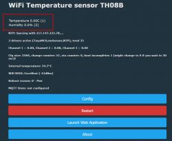
    Please help me set up channels. Temperature and humidity values always show 0.

    WiFi Temperature Sensor TH08B interface with temperature and humidity values at 0.0°C and 0.0%.

    My Autoexec.bat
    startDriver NTP
    startDriver TuyaMCU
    startDriver tmSensor
    ntp_timeZoneOfs 3
    setChannelType 1 temperature_div10
    linkTuyaMCUOutputToChannel 1 val 1
    setChannelType 2 Humidity
    linkTuyaMCUOutputToChannel 2 val 2
    linkTuyaMCUOutputToChannel 3 val 3
    setChannelType 3 ReadOnlyLowMidHigh
    setChannelLabel 3 "Battery Level"
    mqtt_broadcastItemsPerSec 20 


    How can I find out the data that Tuya assigns to channels?

Topic summary

The discussion revolves around the TH08 LCD Calendar/Clock/Temperature/Humidity device, focusing on its teardown, firmware flashing, and integration with OpenBK. Users share experiences with the device's functionality, including issues with sensor readings, MQTT communication, and NTP server configuration. Key points include the necessity of desoldering RX and TX pins for successful firmware flashing, the importance of correct NTP server settings for time synchronization, and methods to maintain Wi-Fi connectivity. Users also explore power management strategies for the device, including the implications of using external power sources and the impact on battery life. Solutions for ensuring accurate temperature and humidity readings are discussed, along with troubleshooting steps for connectivity issues.
Summary generated by the language model.
ADVERTISEMENT