logo elektroda
logo elektroda
X
logo elektroda

Internet radio and audio file player on ESP32-S3

MAJSTER XXL 272154 2718

TL;DR

  • Built an ESP32-S3 internet radio with an audio file player and OLED desk display, evolving through v1, v2, and v3.
  • Uses an ESP32-S3-WROOM-1, PCM5102A DAC, rotary encoders, and GitHub-hosted station lists split into banks of up to 100 stations.
  • The prototype uses a 2.42" 128x64px white OLED display, with a PCB made in Poland costing 130zl.
  • v3 adds a colour screen, weather, a calendar, RSS news from Polsat News Polska, and full remote control.
  • The first PCB had a pad-spacing mistake for the ESP32-S3-WROOM-1, so the module pins had to be bent slightly to fit.
Generated by the language model.
ADVERTISEMENT
Treść została przetłumaczona polish » english Zobacz oryginalną wersję tematu
📢 Listen (AI):
  • #2611 21879926
    DJCheester
    Level 28  
    Posts: 2072
    Help: 75
    Rate: 951
    Theoretically as you write practically not necessarily.

    I have the grounds connected on the PCB and without the display the radio on the board plays perfectly zero hum noise interference.

    When I connect the OLED there is noise and crackling, the inverter is to blame.

    When I supply power to the display from another source, e.g. a second 5v charger, there is silence.

    I am thinking of using this to power the display.

    https://allegro.pl/oferta/przetwornica-separu...-dc-b0505s-1wr3-vout-5v-200ma-hlk-17476660801

    If it works as two power supplies it will be beautiful.

    I've already ordered one and we'll see how it arrives.

    Greetings....
  • ADVERTISEMENT
  • #2612 21880034
    Anonymous
    Level 1  
  • #2613 21881136
    robgold
    Level 23  
    Posts: 722
    Help: 10
    Rate: 290
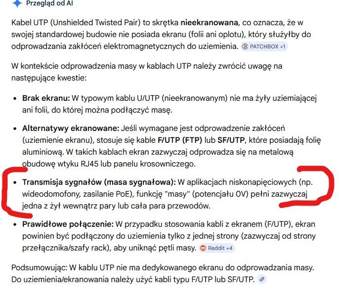
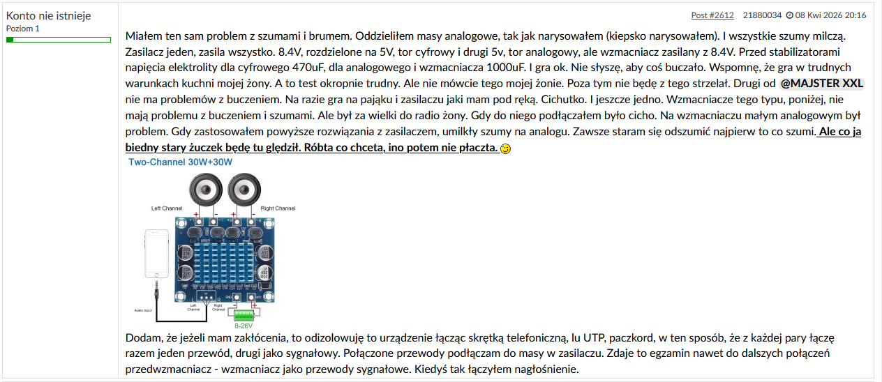
    >>21880034 Theories about correct ground routing I "buy" and agree with 100%. I don't buy the theory about the UTP cable because there is no differential signal from which to eliminate the "common" interference

    @ryba_82 Don't you have OLED flickering after adding the beads ? In my case, this operation caused the inverter to run at the end of its strength.
    Generally the source of the problems is the inverter (non-original) to boost the voltage for the display. Replacing it with an original from Microchip and changing the supply from 3.3 to 5V solves a lot of the problems. The Chinese replacement (what's on the PCB) can't handle a 5V power supply (I slaughtered one). The PCB layout is for these displays drawn "at the knee". The power supply to the inverter is drawn all the way through the PCB and at the end there is not even one capacitor at the inverter input. There is a second version of the PCB for these displays and the layout there is much better done.

    FMT signal is a design mistake. It was supposed to be XSMT (soft mute) so that the DAC could be muted via GPIO. Fortunately there is a series resistor that we don't mount so no ground loop will happen there. The SCK has a short enough connection that there won't be any drop and noise generation there either.

    SPI itself does not generate such fast signals and 10OHm resistors are sufficient. The easiest way to check this is to unplug the 14V inverter from the OLED and apply an external 12V-20V supply to this pin. There will be complete silence.
  • #2614 21881470
    Anonymous
    Level 1  
  • #2615 21881513
    DJCheester
    Level 28  
    Posts: 2072
    Help: 75
    Rate: 951
    robgold wrote:
    Power supply to the inverter pulled all the way through the PCB and at the end there is not even one capacitor at the inverter input.


    And have you tried adding such a capacitor directly on the inverter legs ?

    Greetings ...
  • ADVERTISEMENT
  • #2616 21881730
    robgold
    Level 23  
    Posts: 722
    Help: 10
    Rate: 290
    >>21881513 Yes, I have a 22uF/10V MLCC doped in ( could be 10uF just left over from a Dell laptop repair).
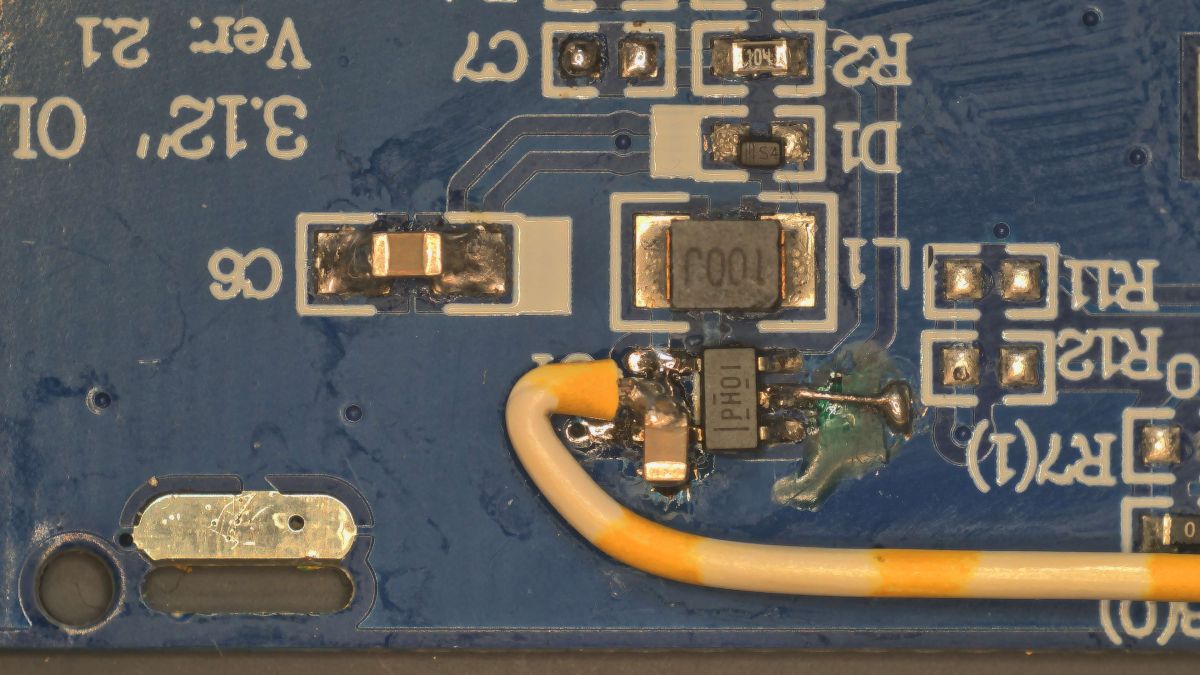
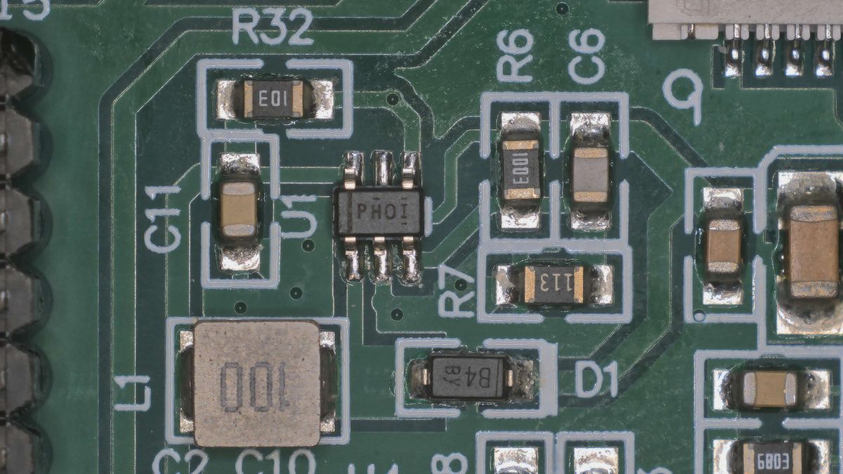
    I have replaced the inverter with a TPS61040DBVR and supply it with 5V instead of 3V. For the large OLED (the 5.5 one) I bumped its voltage up to 15V and it works stably. I will probably still bump it up to 16V.

    Internet radio and audio file player on ESP32-S3

    And here is a picture of the display PCB from Ali, where the layout is much better designed and the inverter is powered from 5V. Microscope photo:
    Internet radio and audio file player on ESP32-S3

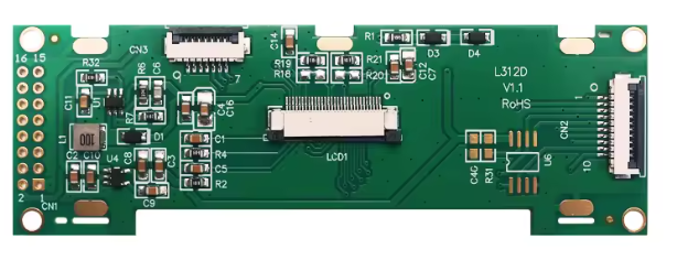
    Here the appearance of the whole PCB:
    Internet radio and audio file player on ESP32-S3

    @kula350 you made something like a "shield" out of UTP cable - question why when there are dedicated shielded audio cables? Good, inexpensive and looks nice.
  • ADVERTISEMENT
  • #2617 21881790
    Anonymous
    Level 1  
  • #2618 21881821
    ArturAVS
    Moderator
    Posts: 26140
    Help: 2295
    Rate: 7745
    kula350 wrote:
    the twist creates capacitance along its length and overall, at each point, drains the high pulses to ground.

    And where in the twisted pair do you get the ground? Unfortunately you are mistaken, it works on a completely different principle.
    kula350 wrote:
    Because if something is radiating, I don't put on ferrites that need to be tuned just

    Sorry, WHAT? What kind of tuning? Nothing is tuned (unless a fool), ferrites are made of materials suitable for the frequency. A core from a noise filter in an RF amplifier will behave completely differently.
    kula350 wrote:
    Ground routing is one way of dissipating that interference which passes right through them.

    This is the key! A wrongly routed ground can spoil a good project.
  • #2619 21882917
    ryba_82
    Level 12  
    Posts: 9
    Rate: 1
    >>21881136 it flickers a little, but this effect is not visible somehow very intensely (blue OLED). Surprisingly, it flickers more in the quieter copies, I have now done such an experiment. By the way, terribly "unique" are these displays. I have 3 units, 1 bought last year, 2 units this year, from a different supplier. Layout the same, but level of interference different. As for the SPI, that was one of my suspicions, I'm basing it here on my professional experience, but actually I haven't observed it in mine. As for the external OLED power supply, some time ago in an act of desperation I wanted to make an external 14V linear power supply to mute the damn thing.
    As for the FMT, I, in my first assembly on a contact board, connected it to ground, by wire, without a resistor. It buzzed very nicely, so I preferred to warn others....
    Chinese replacements for chips from reputable manufacturers are often of inferior quality, e.g. I had this problem on an ESP32-S3 board with an LM1117, theoretically 800mA, and the ESP32 would reset when connecting to WiFi. I suspected the power supply, however on it the 5V was like a wire, without any squat. But for the 3.3V line - here it was fun, as the stabiliser was shutting down at around 360mA. Replacement with an original Texas and the problem disappeared.
  • #2620 21883449
    supsak
    Level 13  
    Posts: 81
    Rate: 5
    Czech colleagues.
    I would like to ask you about the project "Kula350..Cmentarne". Where can you establish a calendar, that would show Slovak men?

    And switching off the radio... OFF, when I switch off or encoder or remote control button on the
    oFF "a svjeczi vyswjetlaczi na cervono Displaj svjeczi.
    How do I switch it on again with the remote control? -nevjem.
    I switch it on only by pressing the encoder button.

    Thank you for your help
  • #2621 21883606
    robgold
    Level 23  
    Posts: 722
    Help: 10
    Rate: 290
    >>21882917 All these displays have a very differently set inverter voltage level. On top of that, I have the impression that this "made in china" TPS "replacement" is very unstable. Especially as they supply it with 3.3V and it is supposed to generate 14.7V from this voltage. Often it fails to do so and because of this it is set to 12V. Everything flashes gently. Swapping to the TPS from the TI and boosting Uwe to 5V solves this. As I wrote this "swap" such a voltage boost doesn't serve because it doesn't seem to have the intended 5V supply voltage. I've also noticed that this higher voltage is most common for the white versions. The green and yellow versions of OLD have it lower. I guess it's a way to make it "durable".

    As for the SPI, also from professional experience I preferred to throw in series resistors on the lines. They are not essential but don't get in the way and after testing I found that this SPI is basically not audible.

    As you can see from your experience they are already counterfeiting even stabilisers ...hands are falling off.
  • #2622 21884421
    ryba_82
    Level 12  
    Posts: 9
    Rate: 1
    >>21883606 Here it may not so much be that the LDO was fake (it had no TI markings), but that it was of poor quality.

    We used to do research in my company wanting to introduce Chinese manufacturers of simple semiconductors. The Chinese can be divided into two groups: reliable companies which are OEMs for e.g. NXP and also sell under their own brand, these have high quality, repeatable parameters, etc., and inferior companies, saving on testing (e.g. my LDO could have been so untested), but also saving on e.g. silicon.

    We had such a case of a stabiliser, or a DC-DC converter, I don't remember exactly. After knocking down the case, we compared the silicon. The Chinese one had half the surface area.... Well no miracles, you can't cheat physics, higher energy density -> faster ageing and degradation. To be clear, the catalogue parameters practically the same.

    There is also a third category, sellers of production waste, which is dealt with by unauthorised dealers, the so-called brokers. You supposedly buy the original, it looks like the original, but it does not hold the parameters. You write to the manufacturer with a complaint, he asks for the label and a photo of the circuit. And you get a reply that the label is a fake or does not match the markings on the circuit (date-code). You have most likely bought a discard from production.

    Sorry for the off-topic
  • #2624 21886170
    robgold
    Level 23  
    Posts: 722
    Help: 10
    Rate: 290
    >>21886120 Any remote control will work, the condition is that it must be an infrared remote control working in the NEC coding as this is the only one implemented. Ask your dealer if this is an IR remote control in the NEC standard. If it is, you can learn it in the Evo on the website under settings/remote config.
  • #2626 21886414
    grzes_dst
    Level 12  
    Posts: 74
    Rate: 7
    @amrowek unfortunately you will not use this remote control in the EVO project.
  • #2627 21886865
    igorkostya0
    Level 1  
    Posts: 1
    Hi, is the interface available in English? Thank you.
  • #2628 21887650
    robgold
    Level 23  
    Posts: 722
    Help: 10
    Rate: 290
    >>21886865 In Evo is in English.
  • #2629 21889272
    DJCheester
    Level 28  
    Posts: 2072
    Help: 75
    Rate: 951
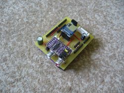
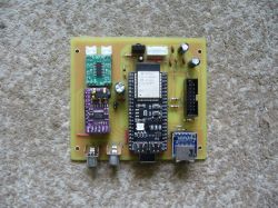
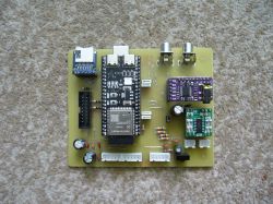
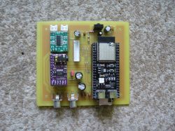
    Hello as a lot of questions about PCBs have come in on priv to me, I am attaching all the PCB versions I have prepared with short descriptions of the versions.
    The summer season is starting so other work takes precedence, so I am making available what I have.

    And yes, briefly the most important information and PCB versions below.

    Here we go ;)

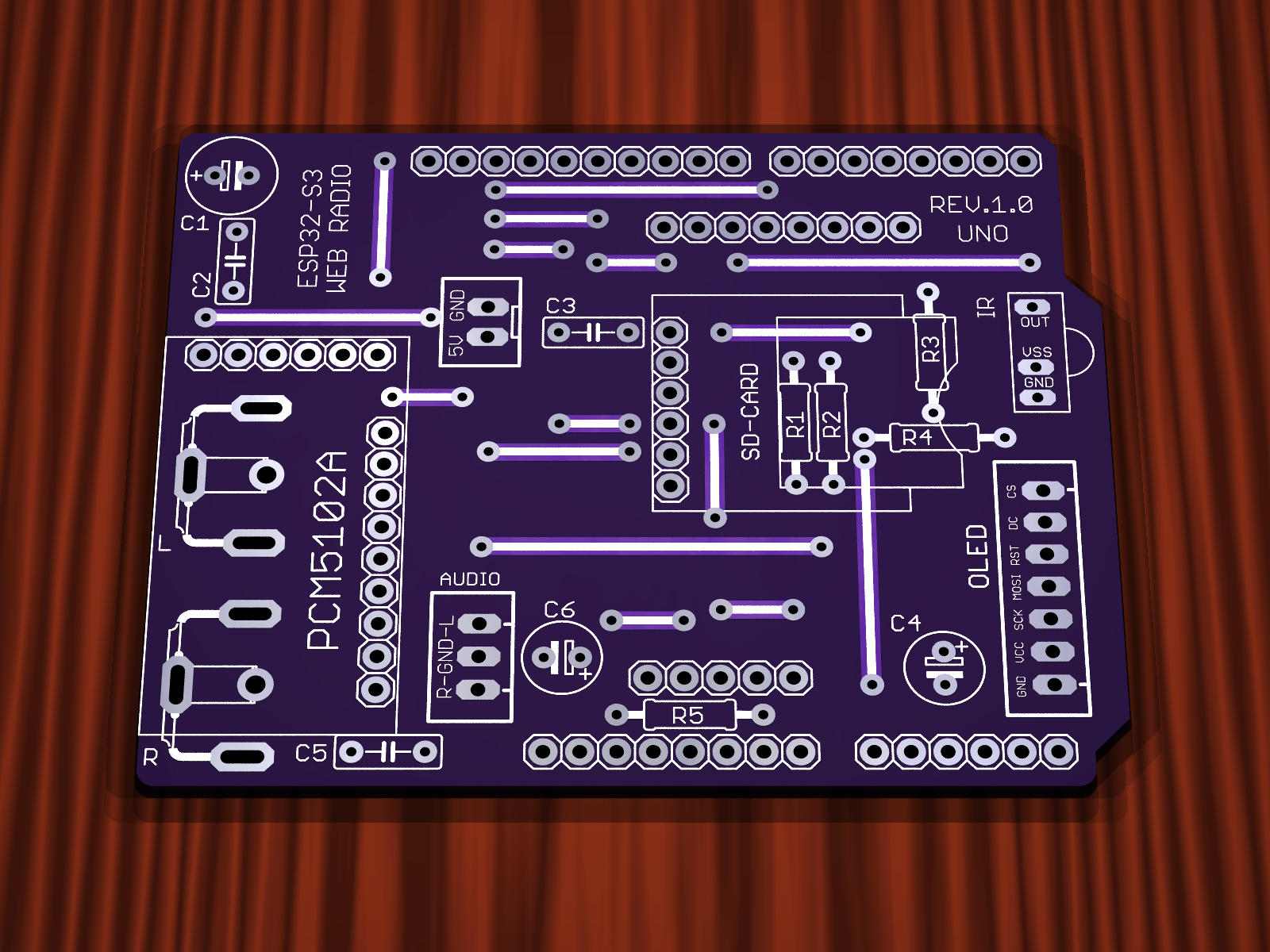
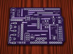
    Version Rev.1.0
    - PCB version without SMD components
    - Jumpers are made on the top layer of the PCB as tracks, so you don't need to assemble them in case of factory PCBs
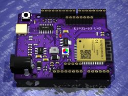
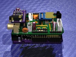
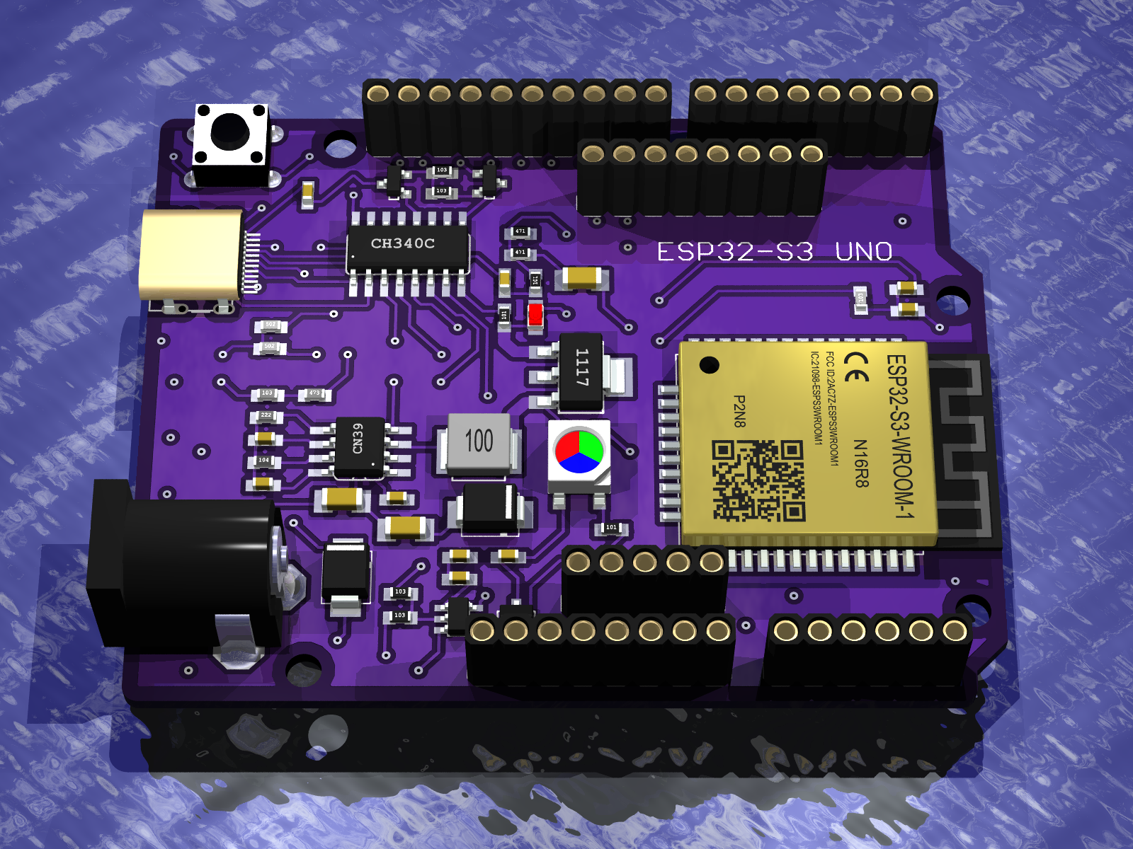
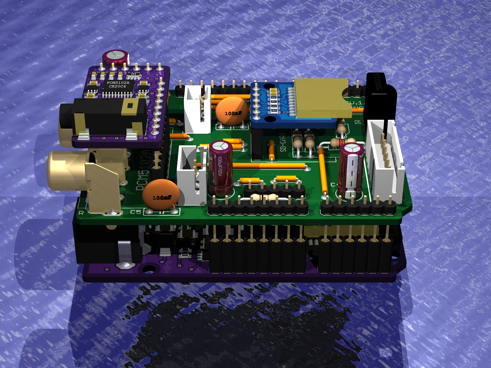
    - Prepared for ESP32S3 Uno (PCB put on sandwich)
    - No encoder output
    - No audio amplifier
    - Audio output on Chinch sockets
    - TSOP31238 infrared receiver
    - 7-pin connector for OLED display
    - Connector 3-pin - audio output for external amplifier
    - Connector 2-pin - derived 5V power supply for external amplifier
    - Robgold's software upload
    - Dimensions - board size the same as the ESP32S3 UNO board - or Arduino UNO)

    Internet radio and audio file player on ESP32-S3 Internet radio and audio file player on ESP32-S3 Internet radio and audio file player on ESP32-S3


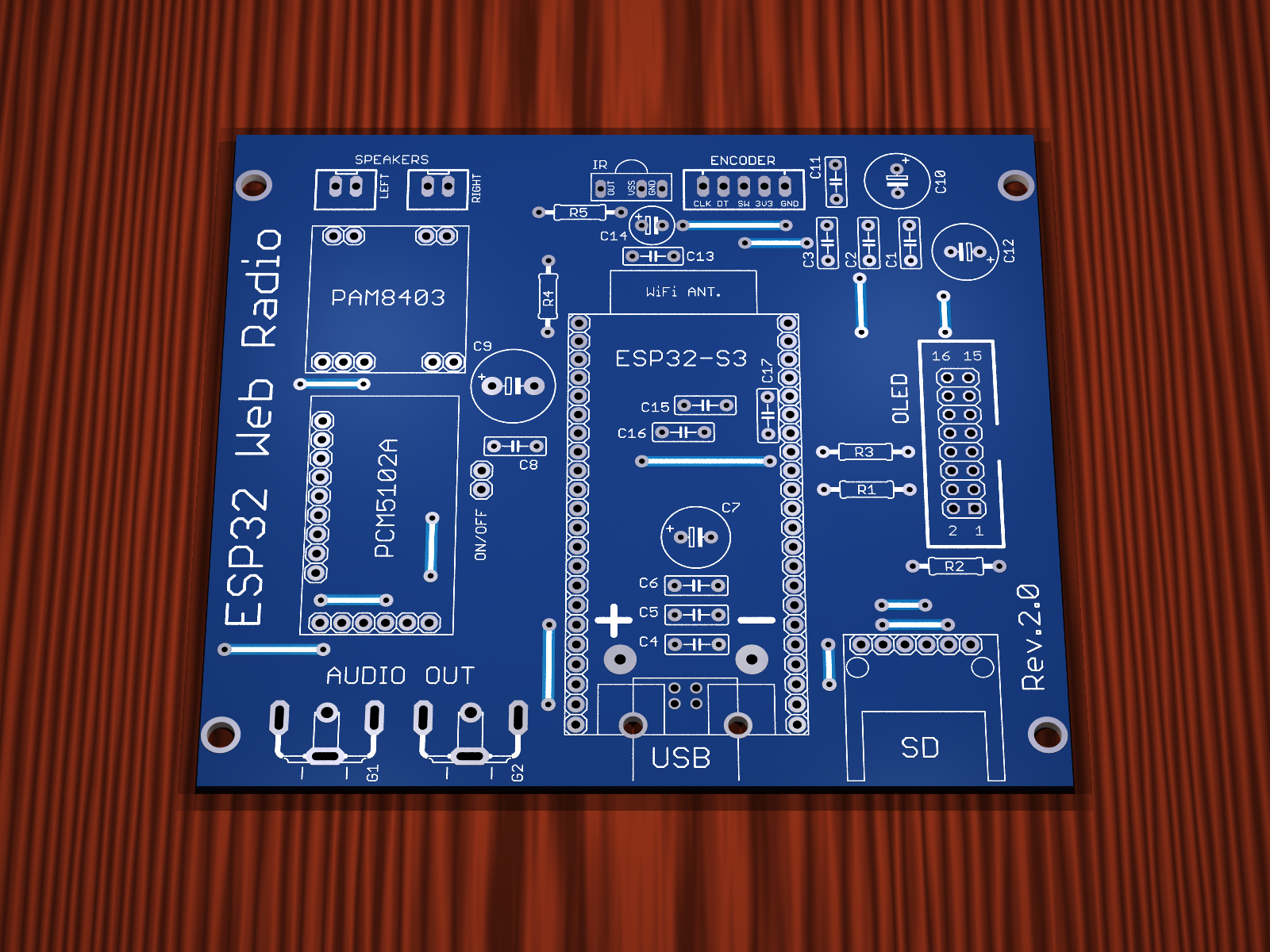
    Version Rev.2.0
    - PCB version without SMD components
    - The jumpers are made on the top layer of the PCB as tracks, so they do not need to be mounted in case of factory PCBs
    - PCB version with one encoder
    - Audio output on Chinch sockets
    - TSOP31238 infrared receiver
    - 16-pin connector for OLED display
    - Audio amplifier PAM8403
    - Power supply USB printer socket
    - Robgold col's software upload
    - Dimensions 99.95mm x 88.54mm
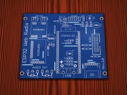

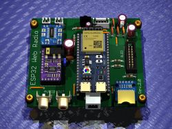
    Internet radio and audio file player on ESP32-S3 Internet radio and audio file player on ESP32-S3


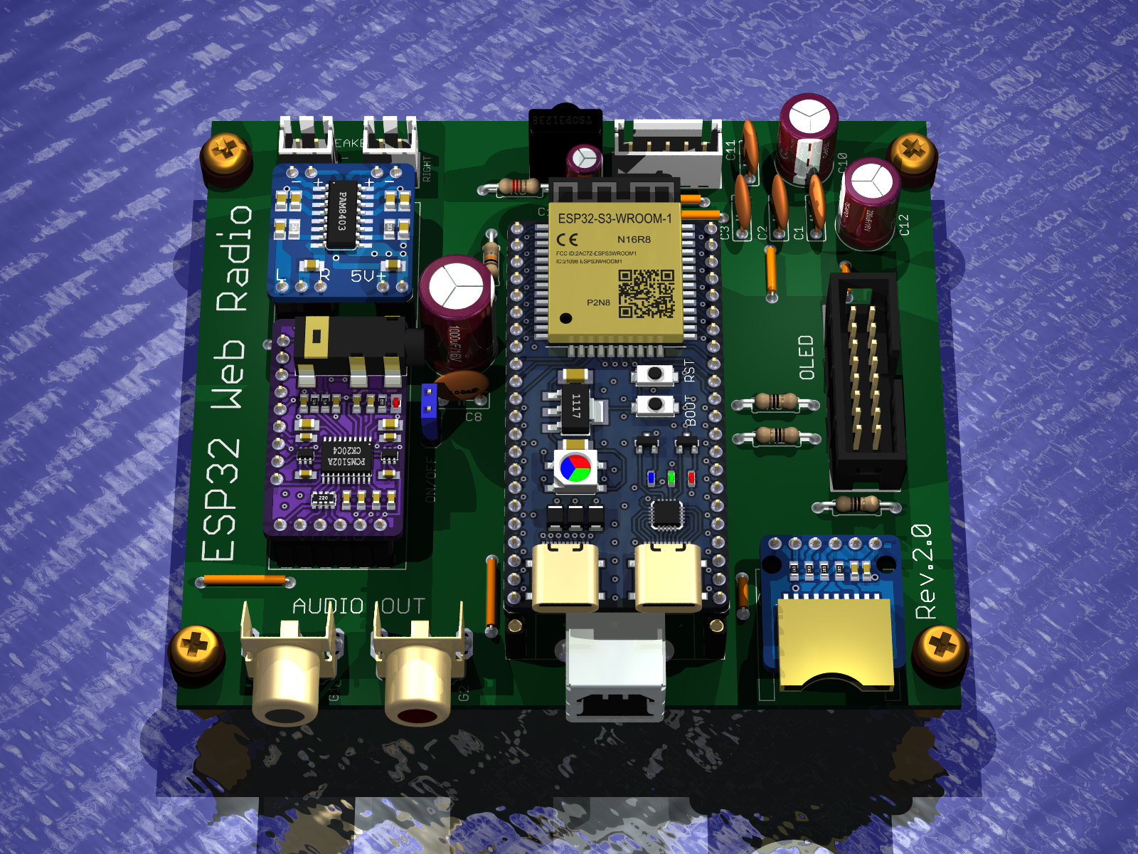
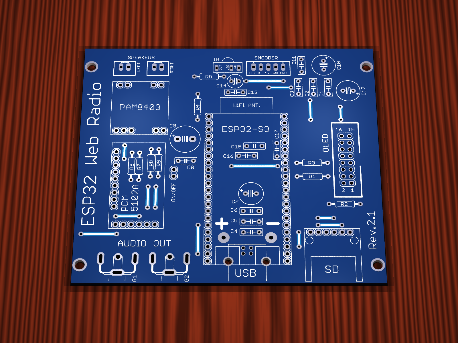
    Version Rev.2.1
    - Everything as in Rev.2.0
    - Added voltage dividers for the audio signal to reduce the audio level at the input of the PAM8403 power amplifier


    Internet radio and audio file player on ESP32-S3 Internet radio and audio file player on ESP32-S3


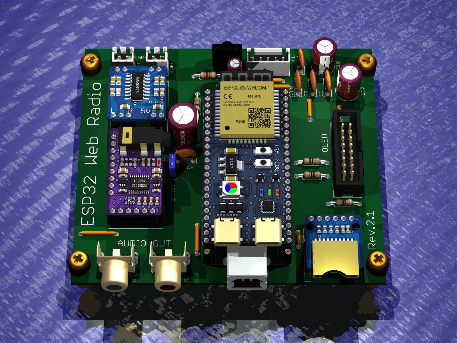
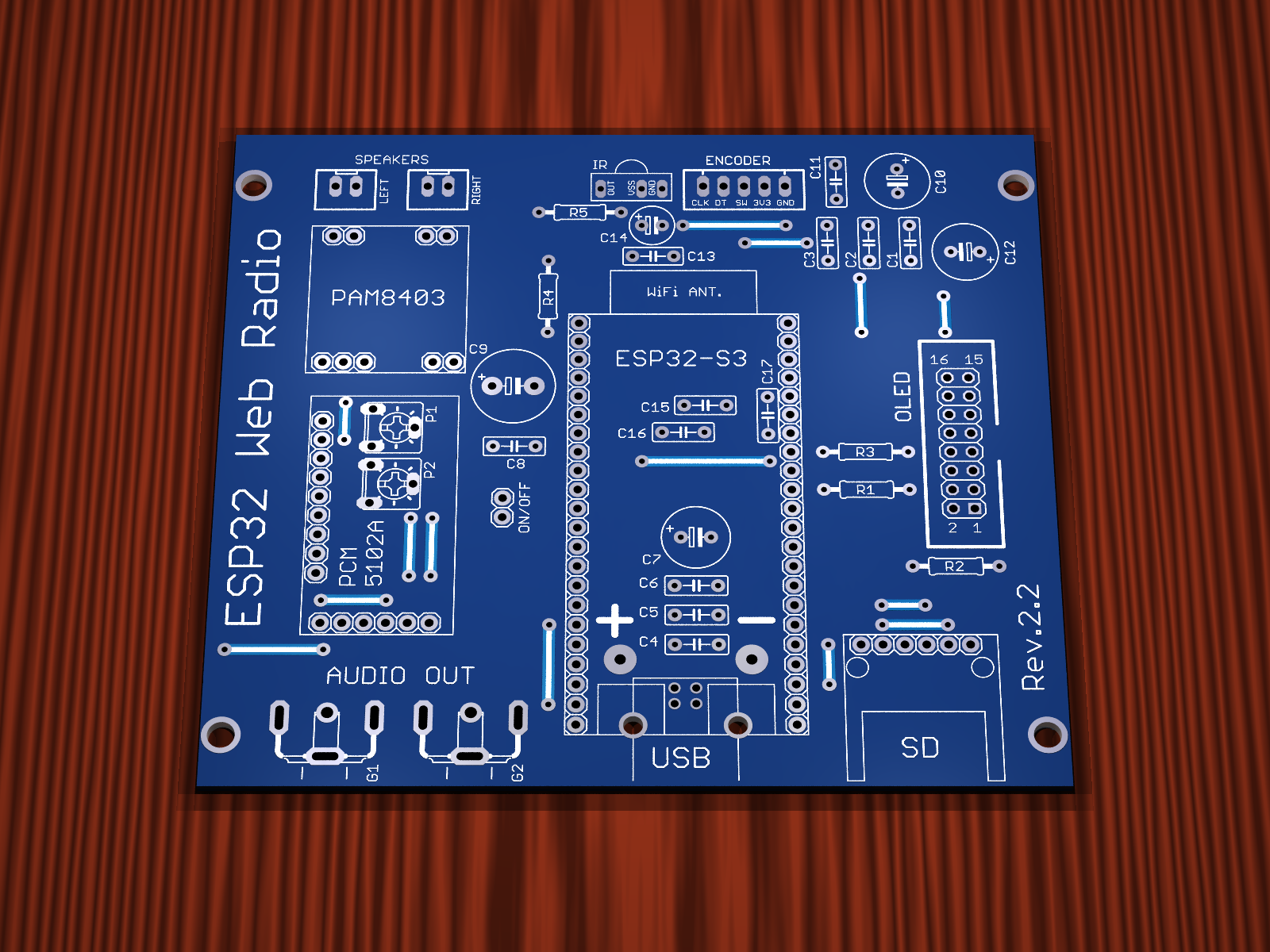
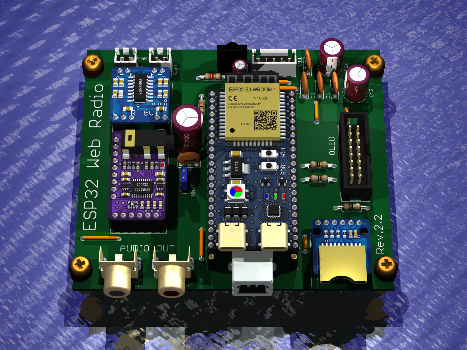
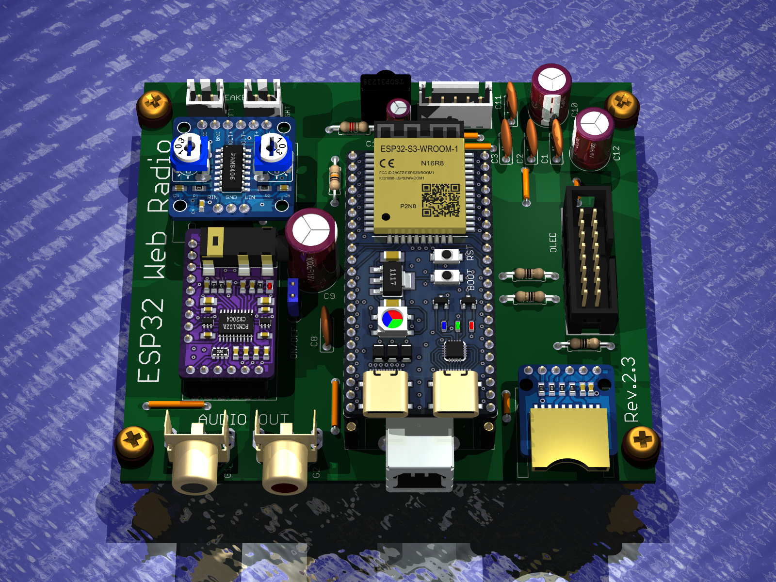
    Version Rev.2.2
    - Everything as in Rev.2.0
    - Added potentiometers for the audio signal to adjust the audio level at the input of the PAM8403 power amplifier


    Internet radio and audio file player on ESP32-S3 Internet radio and audio file player on ESP32-S3


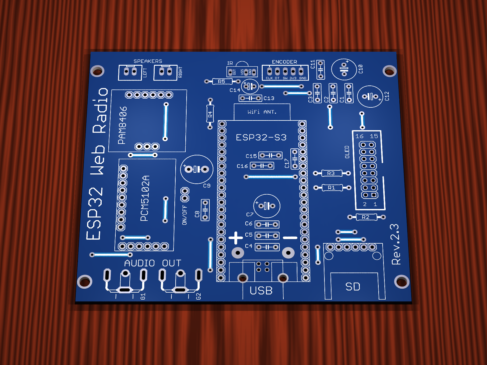
    Version Rev.2.3
    - Everything as in Rev.2.0
    - Power amplifier has been changed, PAM8403 has been removed and PAM8406 amplifier module has been used


    Internet radio and audio file player on ESP32-S3 Internet radio and audio file player on ESP32-S3


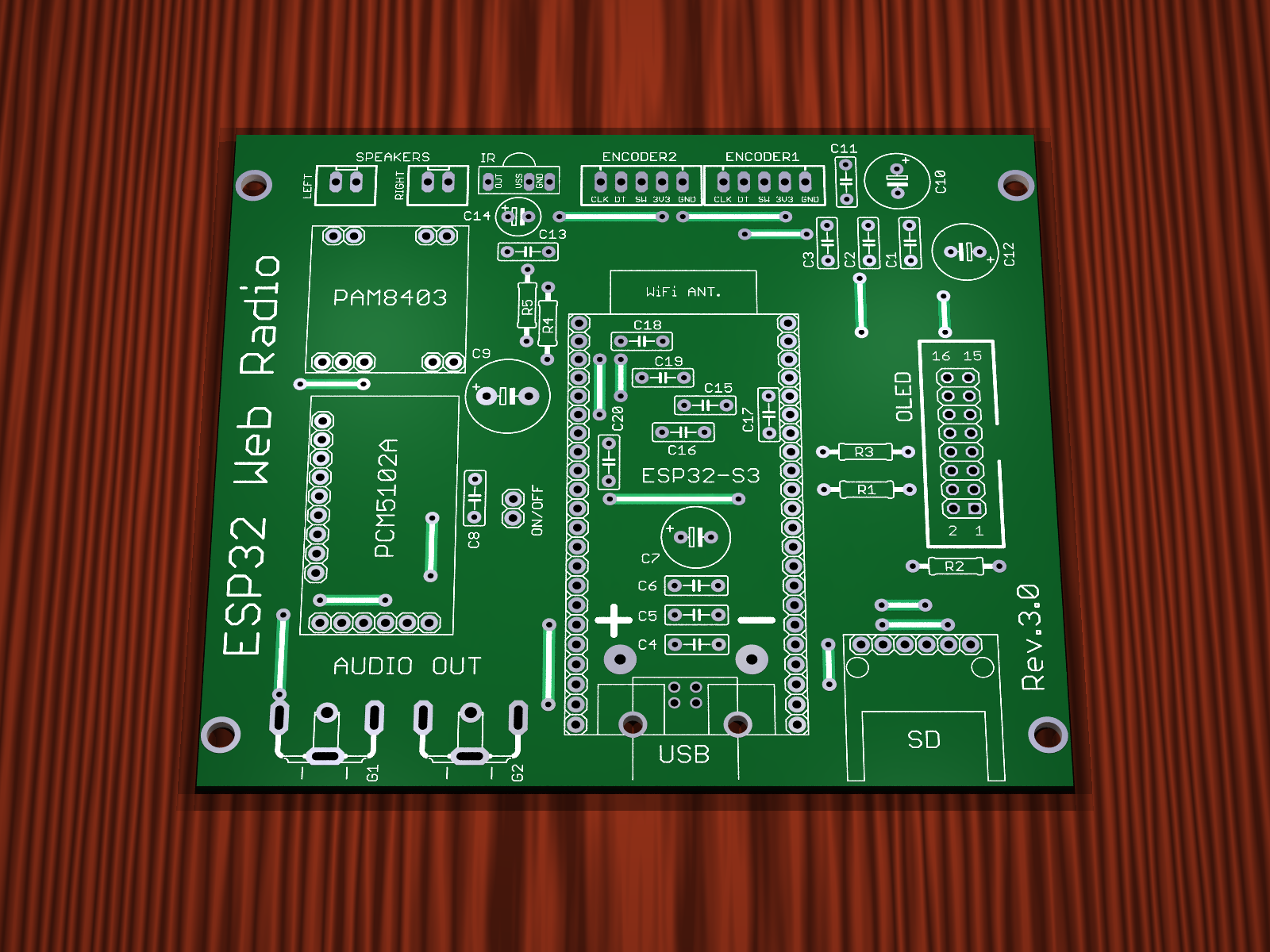
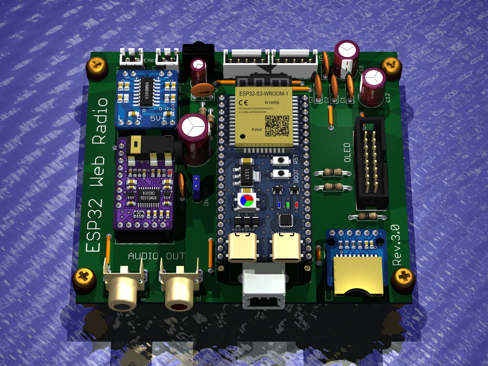
    Version Rev.3.0
    - PCB version without SMD components
    - Jumpers are made on the top layer of the PCB as tracks, so they do not need to be mounted in case of factory PCBs
    - PCB version with two encoders
    - Audio output on Chinch sockets
    - TSOP31238 infrared receiver
    - 16-pin connector for OLED display
    - Audio amplifier PAM8403
    - Power supply USB printer socket
    - Robgold col's software upload
    - Dimensions 99.95mm x 88.54mm

    Internet radio and audio file player on ESP32-S3 Internet radio and audio file player on ESP32-S3


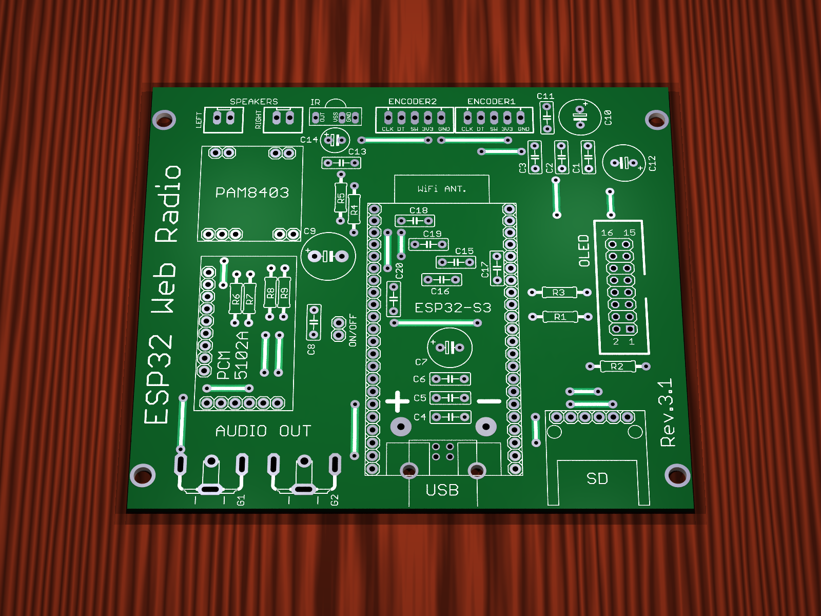
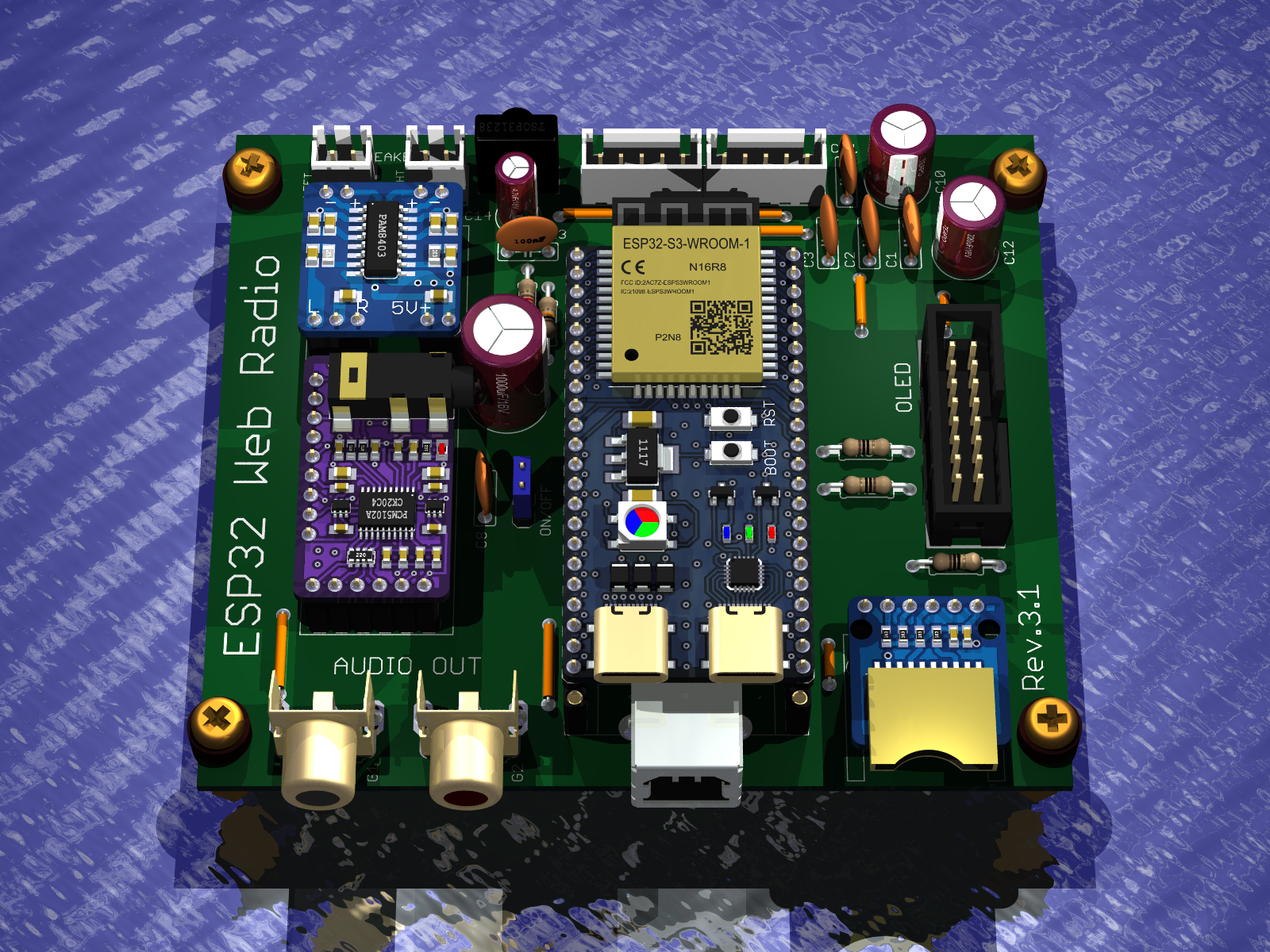
    Version Rev.3.1
    - Everything as in Rev.3.0
    - Added voltage dividers for audio signal to reduce audio input level power amplifier PAM8403


    Internet radio and audio file player on ESP32-S3 Internet radio and audio file player on ESP32-S3


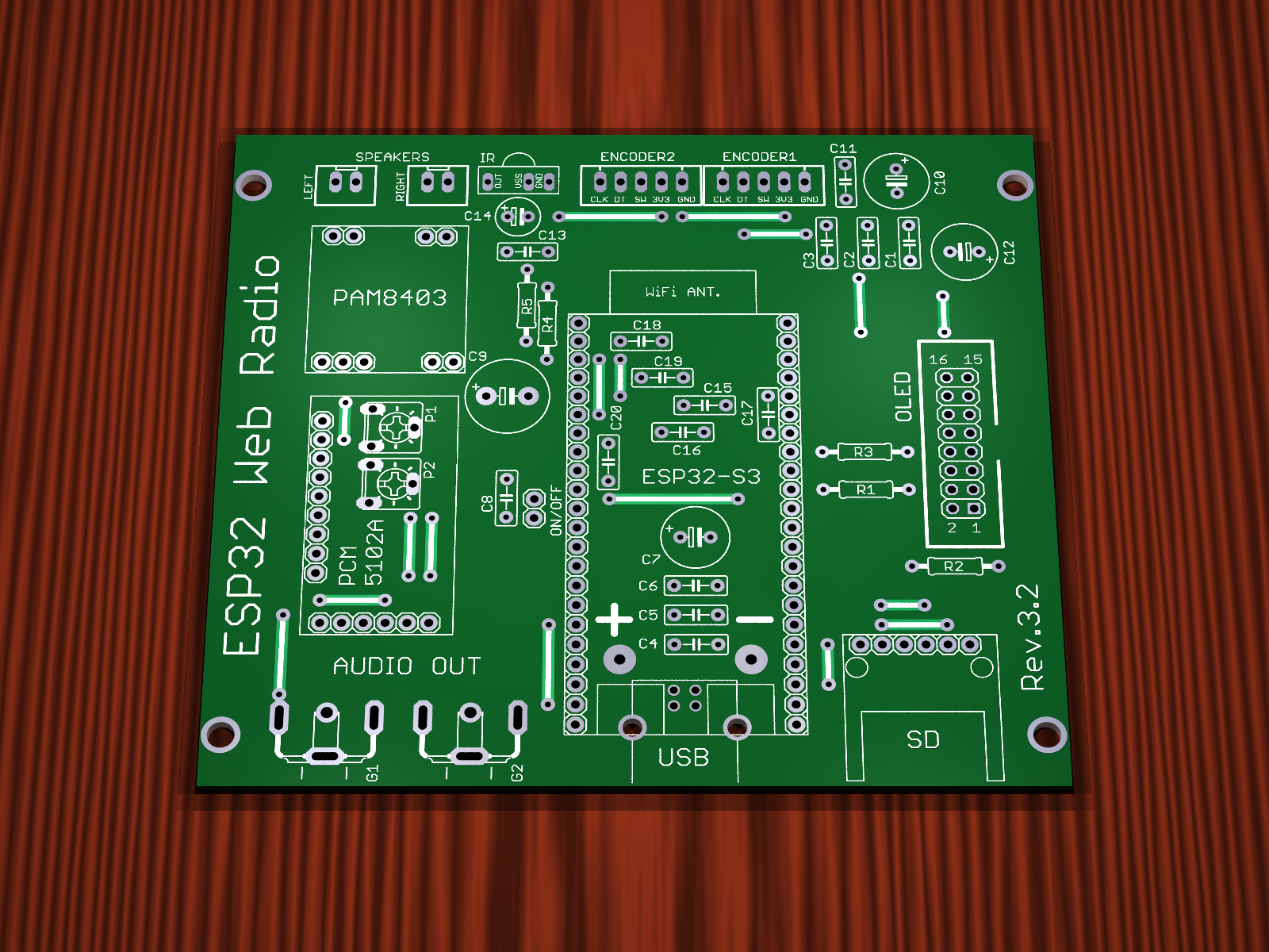
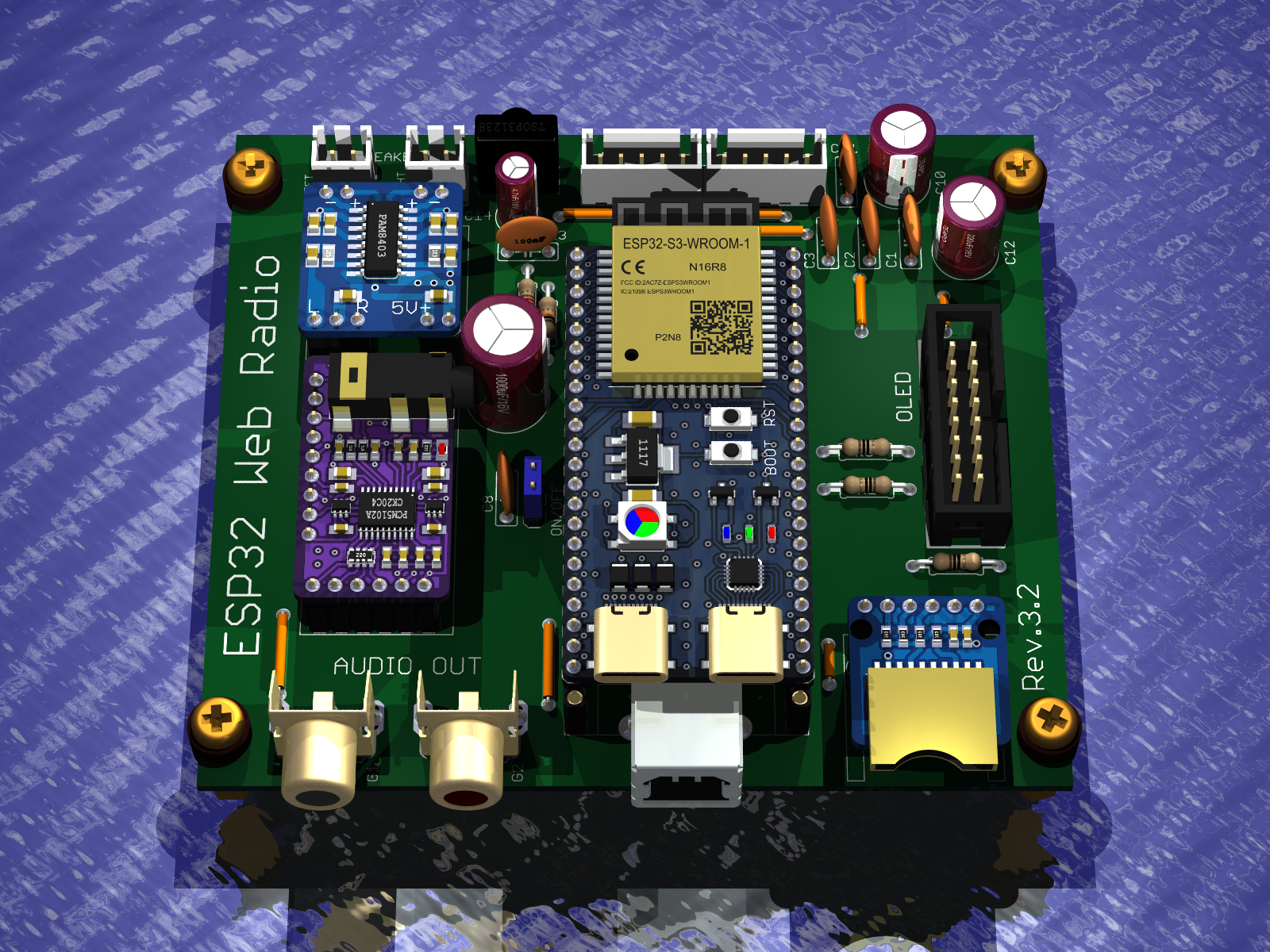
    Version Rev.3.2
    - Everything as in Rev.3.0
    - Added potentiometers for the audio signal to adjust the audio level at the input of the PAM8403 power amplifier


    Internet radio and audio file player on ESP32-S3 Internet radio and audio file player on ESP32-S3


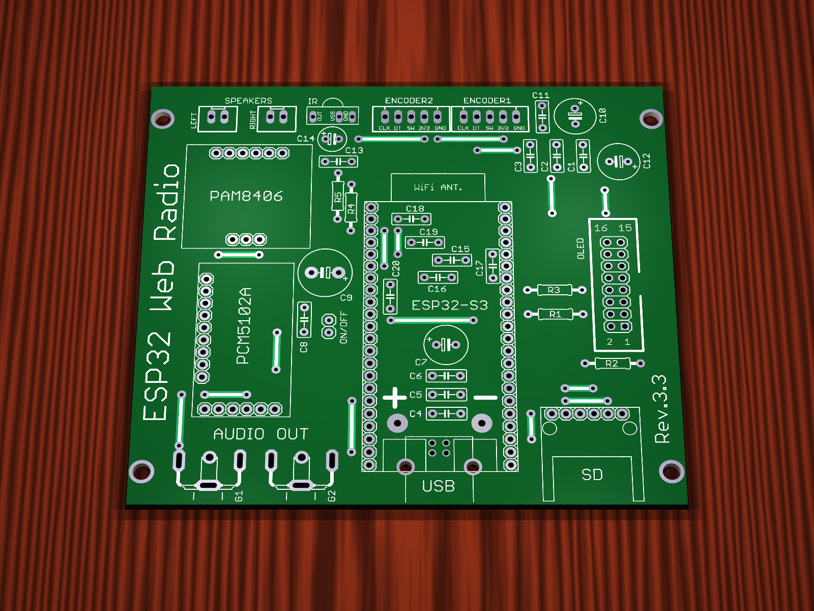
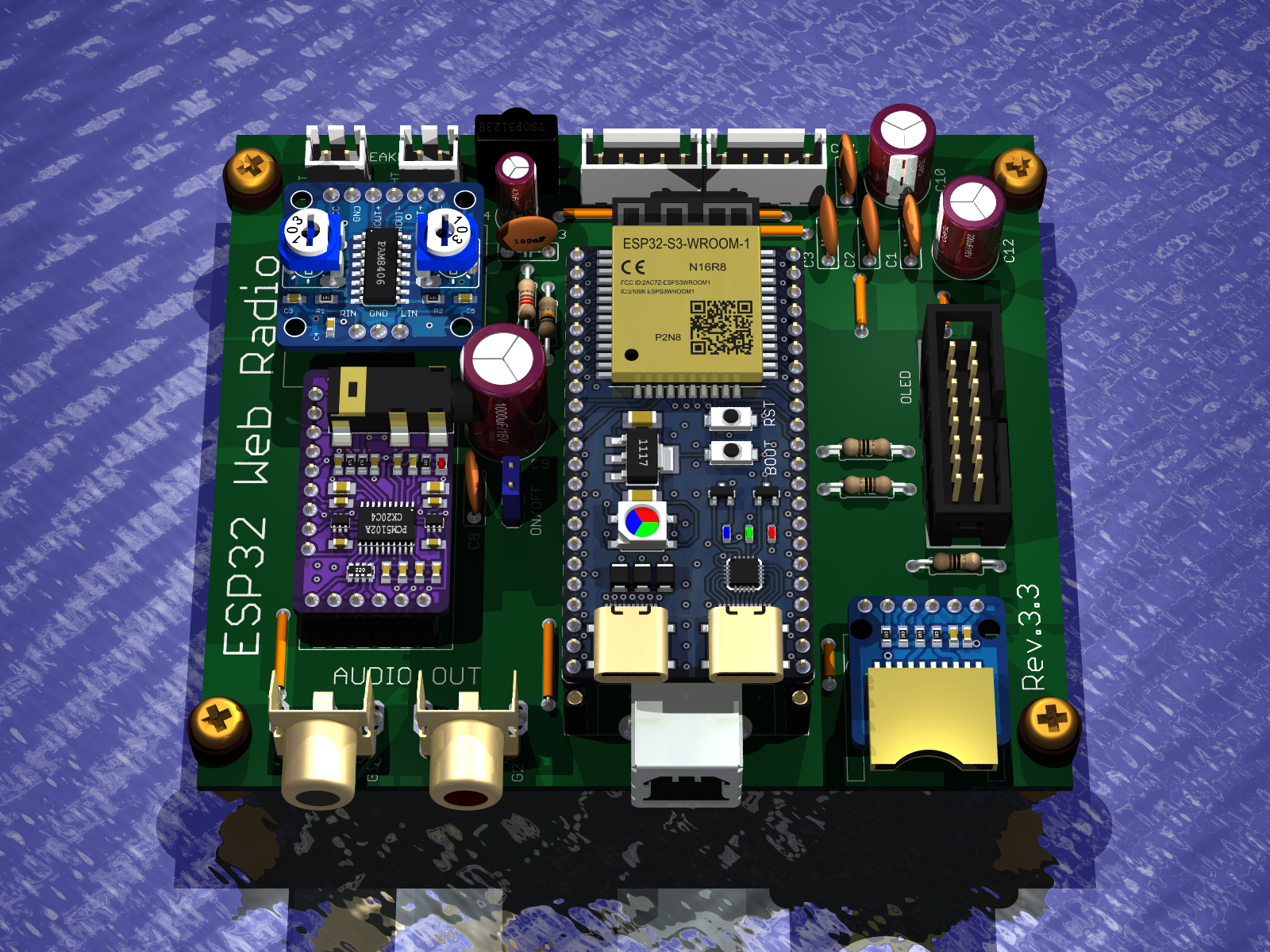
    Version Rev.3.3
    - Everything as in Rev.3.0
    - Power amplifier has been changed, PAM8403 has been removed and PAM8406 amplifier module has been used


    Internet radio and audio file player on ESP32-S3 Internet radio and audio file player on ESP32-S3


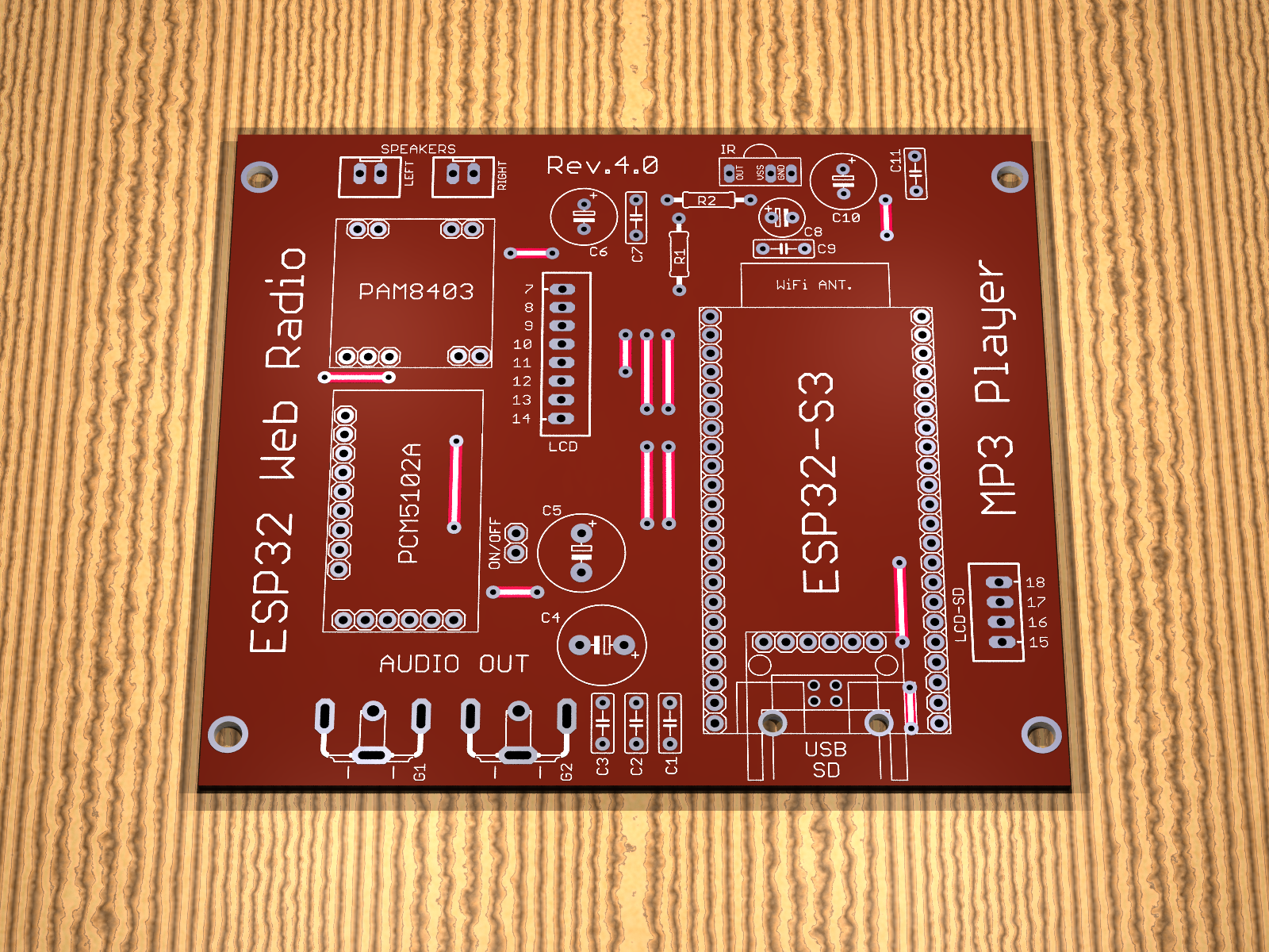
    Version Rev.4.0
    - PCB version without SMD components
    - The jumpers are made on the top layer of the PCB as tracks, so they do not need to be mounted on the factory PCBs
    - PCB version without encoders
    - Audio output on Chinch sockets
    - TSOP31238 infrared receiver
    - Connector 8-pin for LCD display
    - 4-pin connector for SD card reader on display
    - Note: Do not use two card readers at the same time !!!
    - Audio amplifier PAM8403
    - Power supply USB printer socket
    - MAJSTER XXL software preload
    - Dimensions 98.04mm x 87.25mm


    Internet radio and audio file player on ESP32-S3 Internet radio and audio file player on ESP32-S3


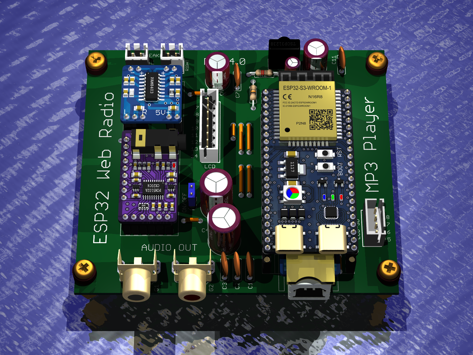
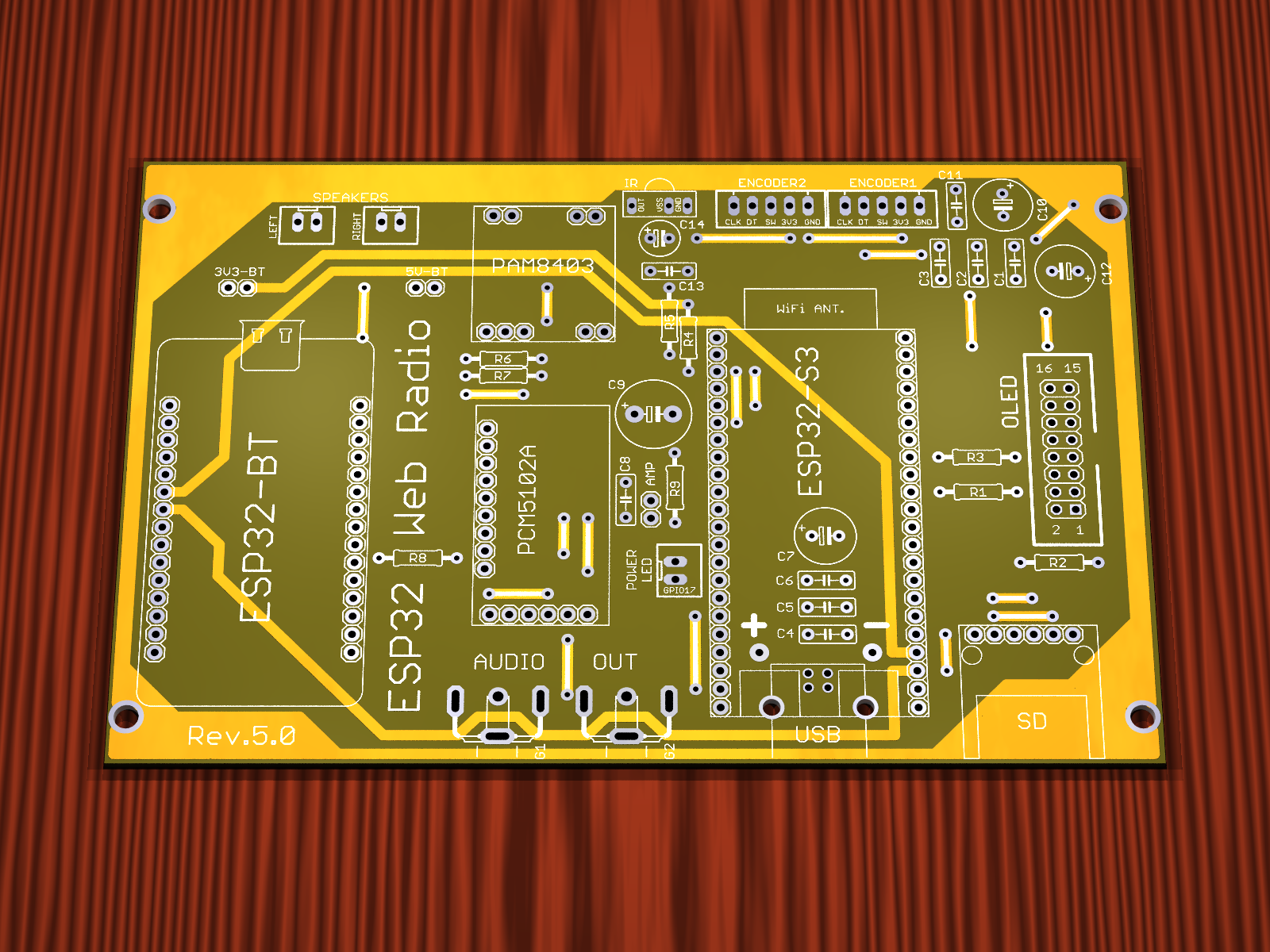
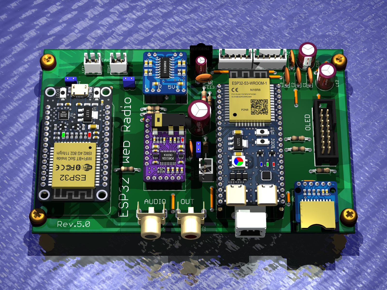
    Version Rev.5.0
    - PCB version without SMD components
    - Jumpers are made on the top layer of the PCB as tracks, so they do not need to be mounted in case of factory PCBs
    - PCB version with two encoders
    - Audio output on Chinch sockets
    - TSOP31238 infrared receiver
    - 16-pin connector for OLED display
    - Audio amplifier PAM8403
    - Power supply USB printer socket
    - Version contains two ESP32 modules the second one for BT transmission
    - Uploaded soft by kol Ejcon (mod of original soft by kol Robgold)
    - Dimensions 135.26mm x 88.27mm


    Internet radio and audio file player on ESP32-S3 Internet radio and audio file player on ESP32-S3


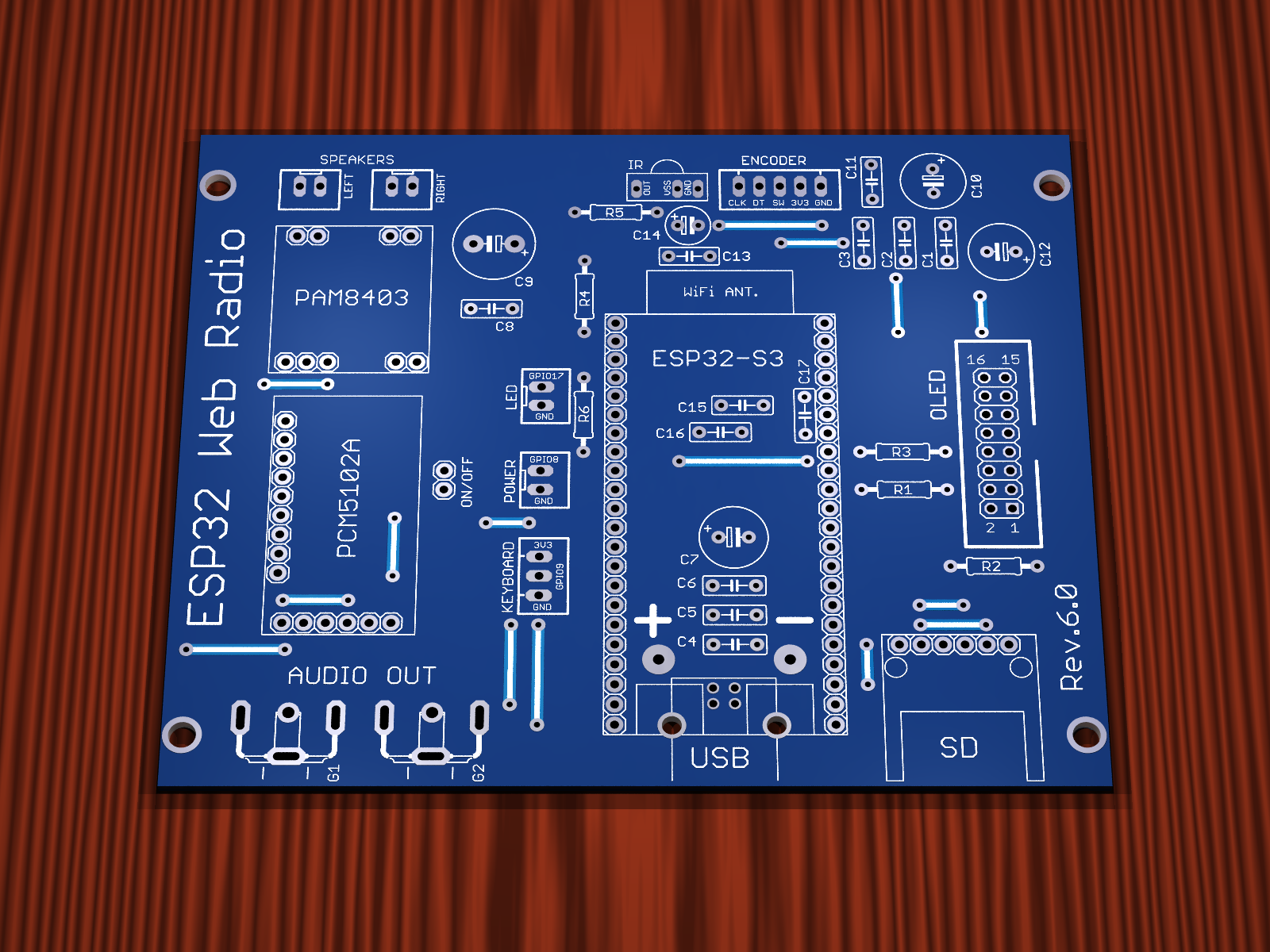
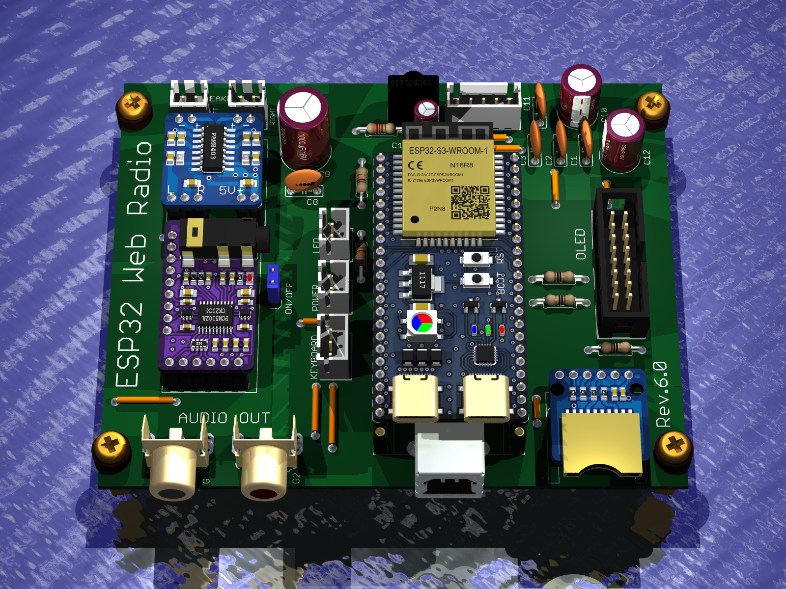
    Version Rev.6.0
    - PCB version without SMD components
    - The jumpers are made on the top layer of the PCB as tracks, so they do not need to be mounted in case of factory PCBs
    - PCB version with one encoder
    - Audio output on Chinch sockets
    - TSOP31238 infrared receiver
    - 16-pin connector for OLED display
    - Audio amplifier PAM8403
    - Power supply USB printer socket
    - Connector 2-pin for POWER LED
    - Connector 2-pin for POWER button
    - Connector 3-pin for ADC keyboard connection
    - Robgold software upload
    - Dimensions 108.84mm x 88.54mm


    Internet radio and audio file player on ESP32-S3 Internet radio and audio file player on ESP32-S3


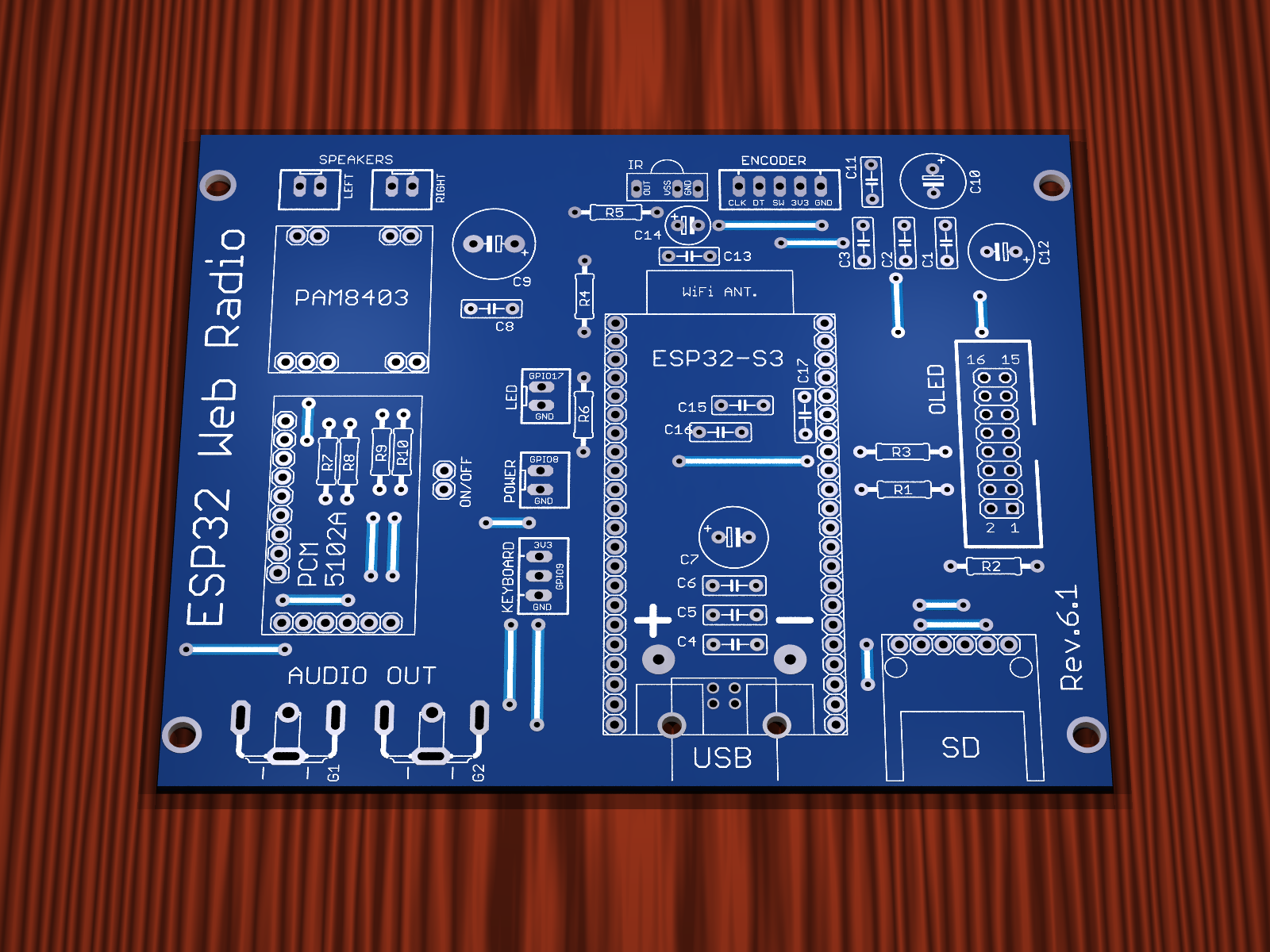
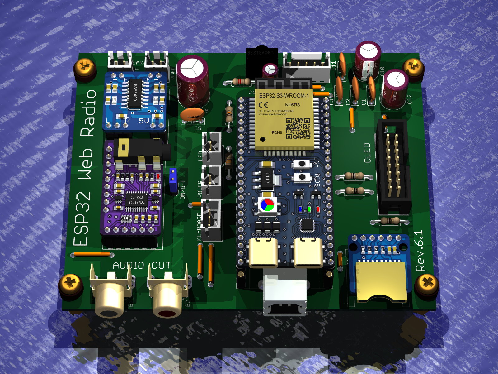
    Version Rev.6.1
    - Everything as in Rev.6.0
    - Added voltage dividers for the audio signal to reduce the audio level at the input of the PAM8403 power amplifier
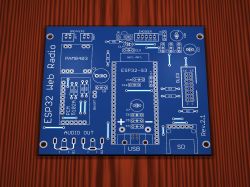
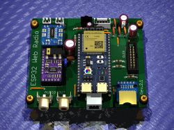
    Internet radio and audio file player on ESP32-S3 Internet radio and audio file player on ESP32-S3


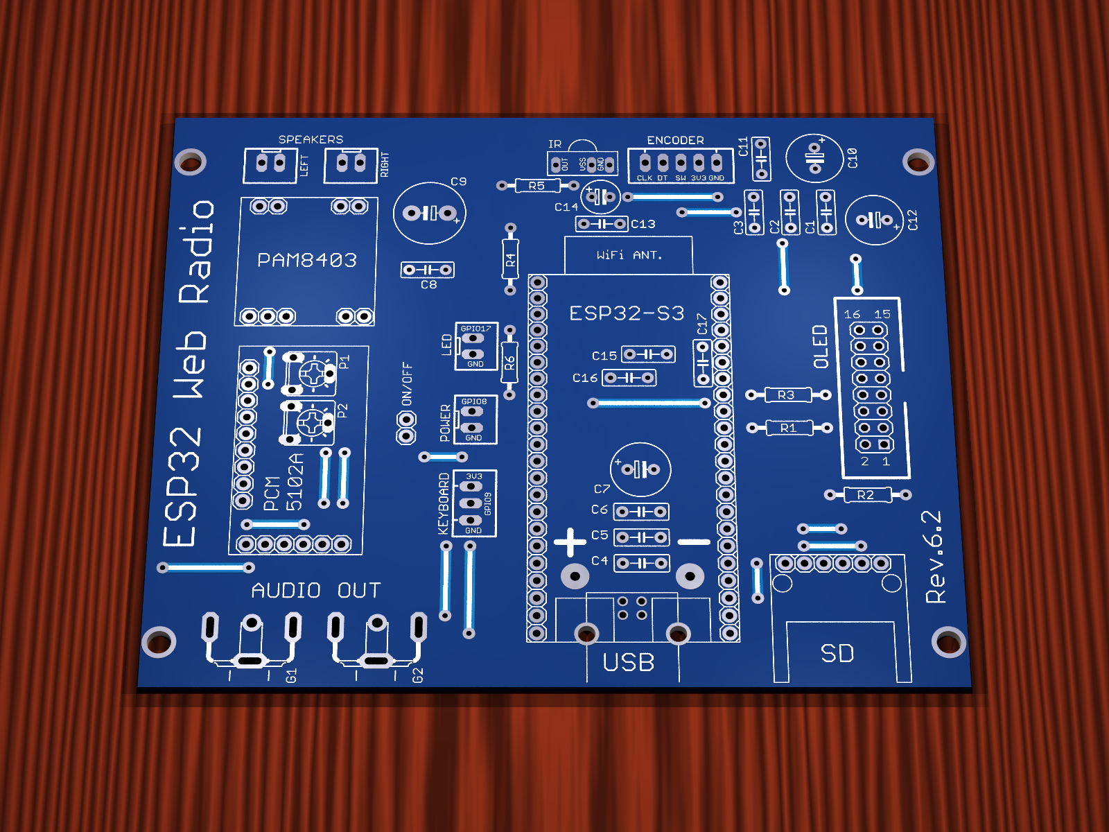
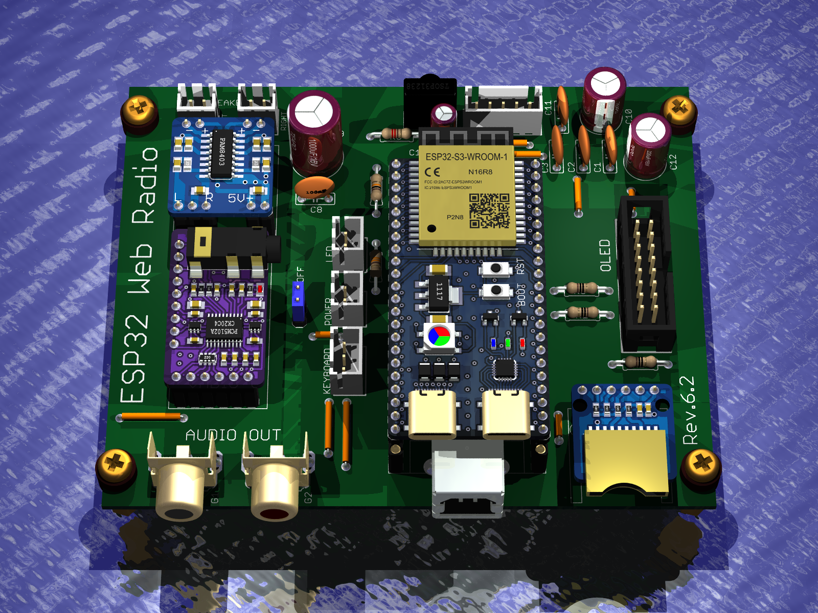
    Version Rev.6.2
    - Everything as in Rev.6.0
    - Added potentiometers for the audio signal to adjust the audio level at the input of the PAM8403 power amplifier
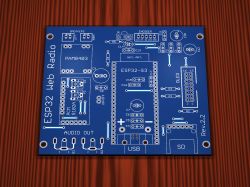
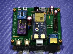
    Internet radio and audio file player on ESP32-S3 Internet radio and audio file player on ESP32-S3


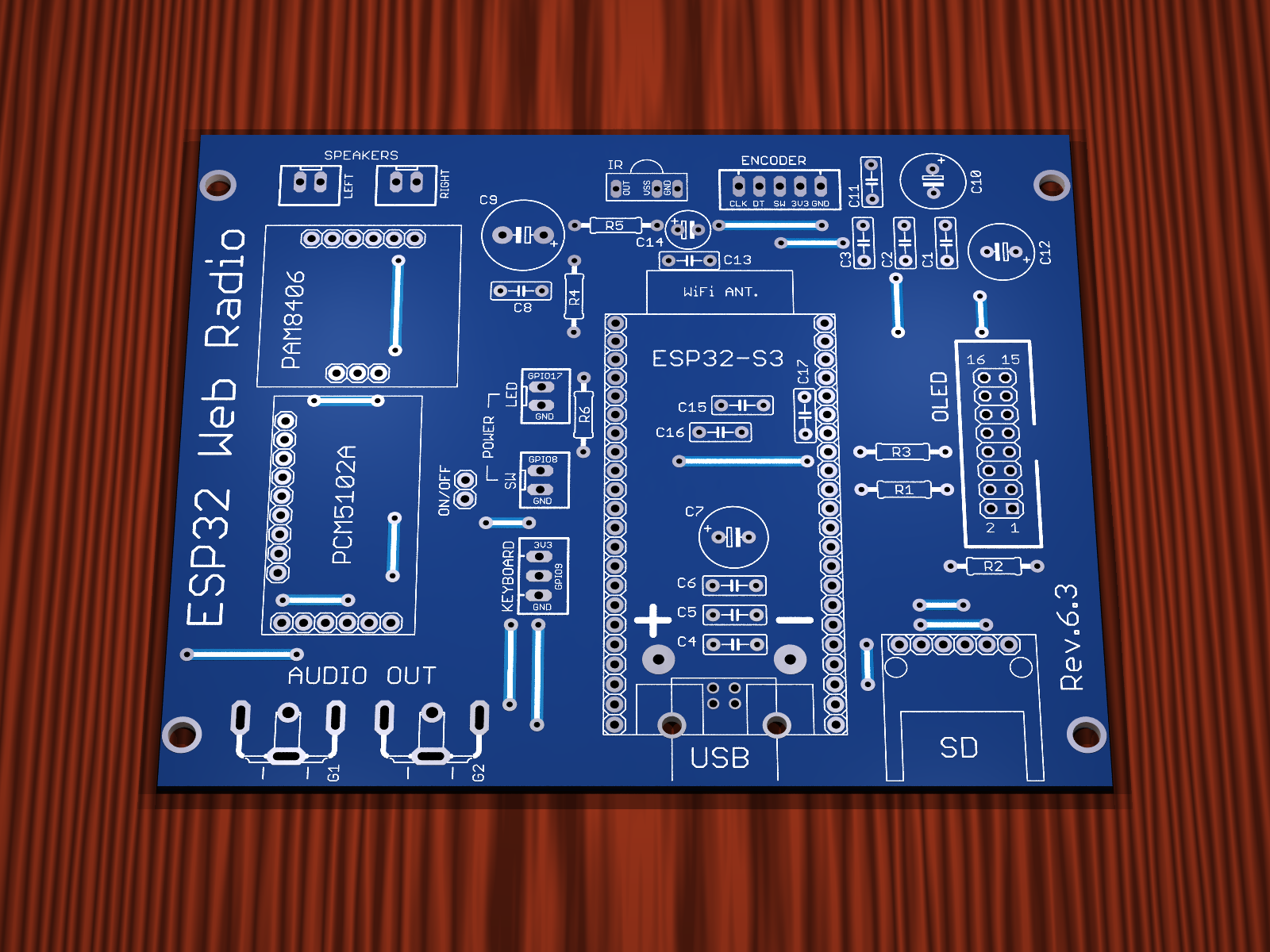
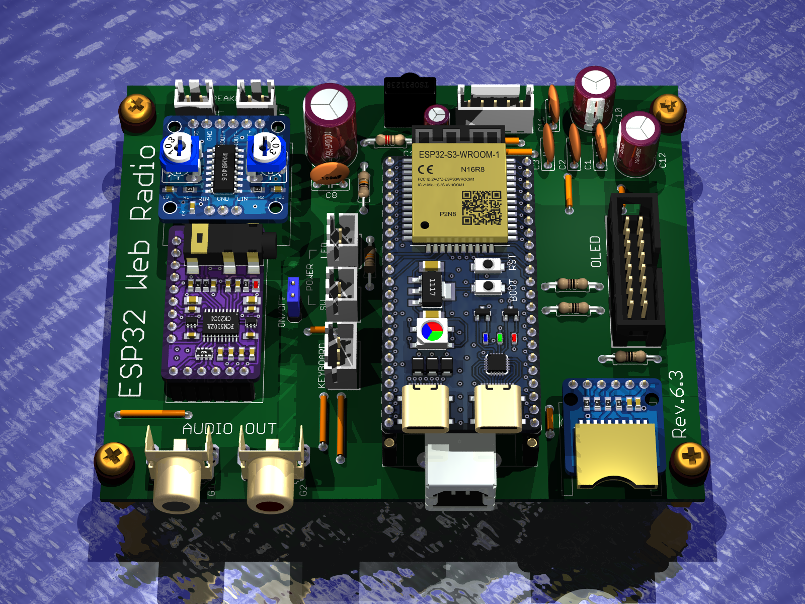
    Version Rev.6.3
    - Everything as in Rev.6.0
    - Power amplifier has been replaced PAM8403 has been removed and PAM8406 amplifier module has been used


    Internet radio and audio file player on ESP32-S3 Internet radio and audio file player on ESP32-S3


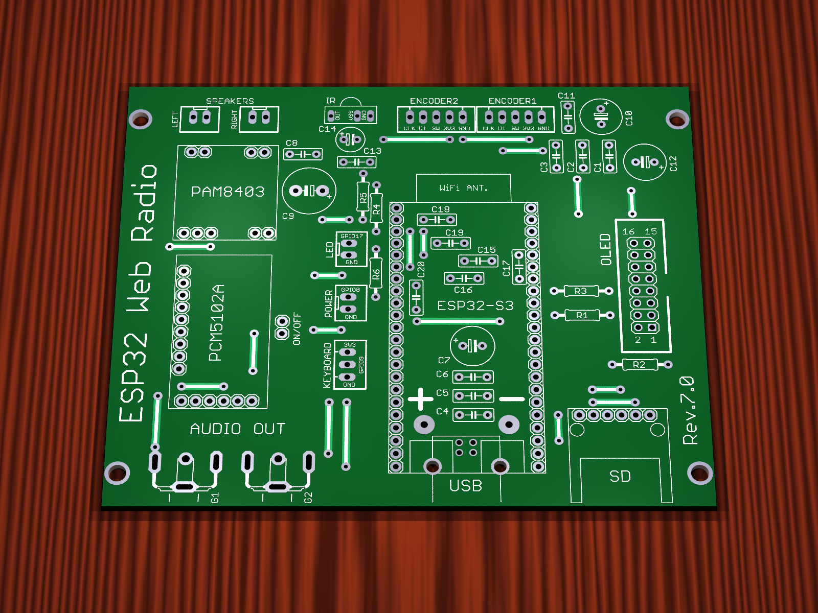
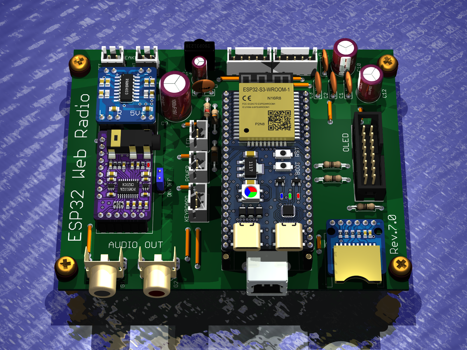
    Version Rev.7.0
    - PCB version without SMD components
    - Jumpers are made on the top layer of the PCB as tracks, so they do not need to be mounted in case of factory PCBs
    - PCB version with two encoders
    - Audio output on Chinch sockets
    - TSOP31238 infrared receiver
    - 16-pin connector for OLED display
    - Audio amplifier PAM8403
    - Power supply USB printer socket
    - Connector 2-pin for POWER LED
    - Connector 2-pin for POWER button
    - Connector 3-pin for ADC keyboard connection
    - Robgold software upload
    - Dimensions 108.84mm x 88.54mm


    Internet radio and audio file player on ESP32-S3 Internet radio and audio file player on ESP32-S3


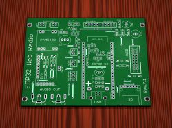
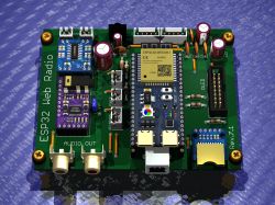
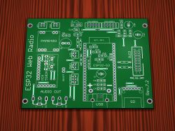
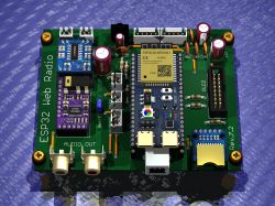
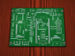
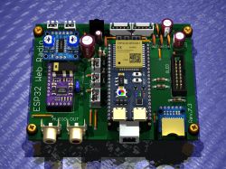
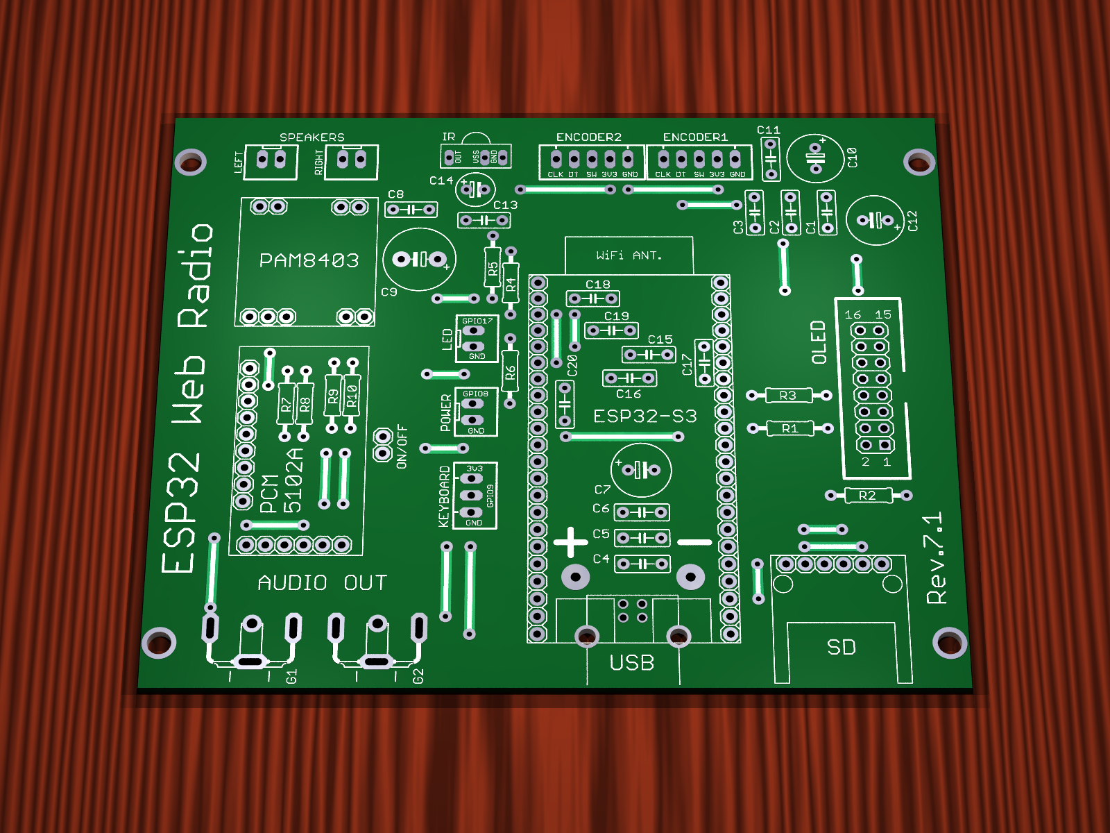
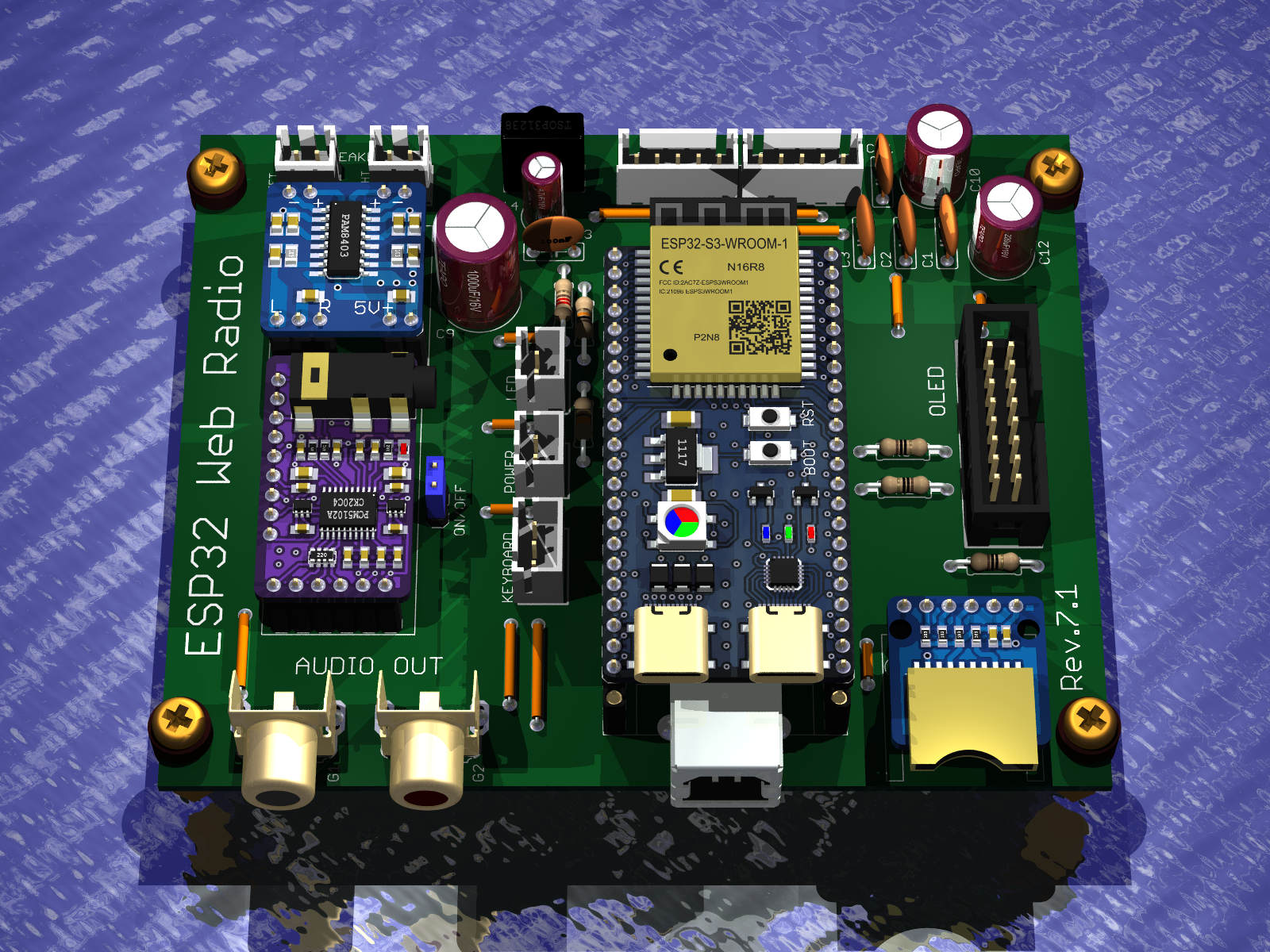
    Version Rev.7.1
    - Everything as in Rev.7.0
    - Added voltage dividers for the audio signal to reduce the audio level at the input of the PAM8403 power amplifier


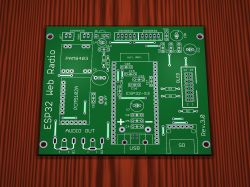
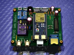
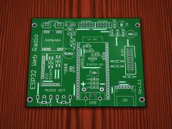
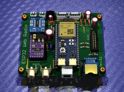
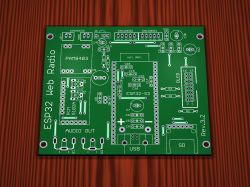
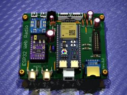
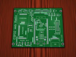
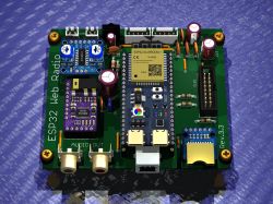
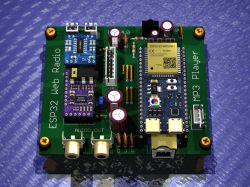
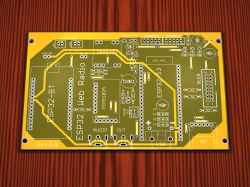
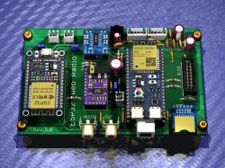
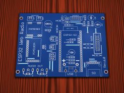
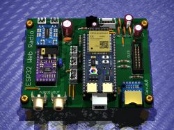
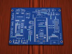
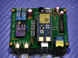
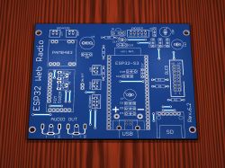
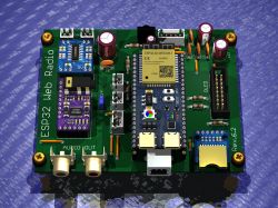
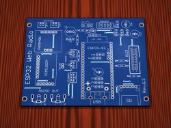
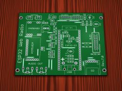
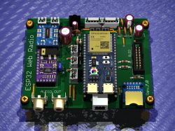
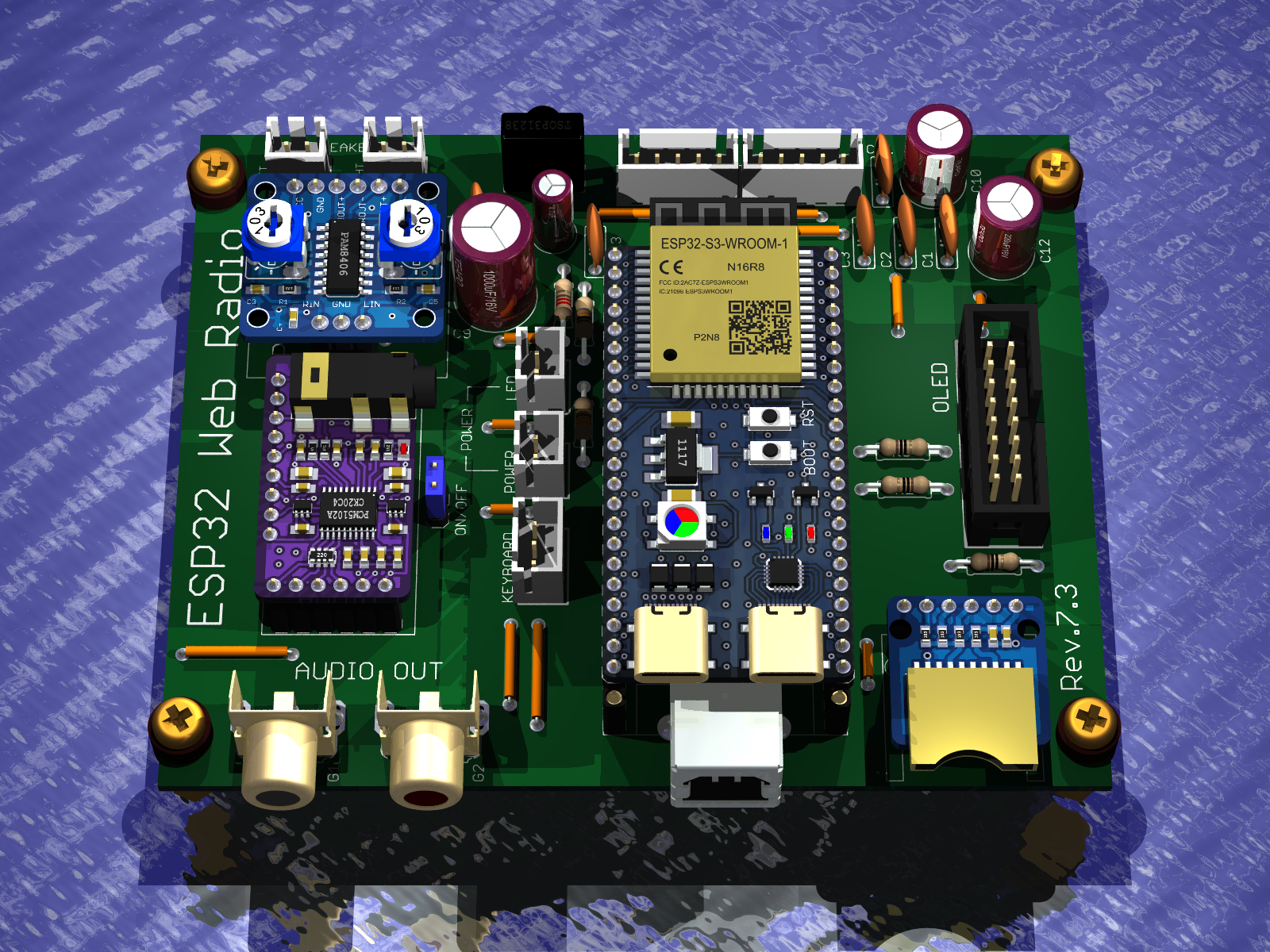
    Internet radio and audio file player on ESP32-S3 3D render of “ESP32 Web Radio” PCB with ESP32-S3 module, OLED header, and RCA audio outputs


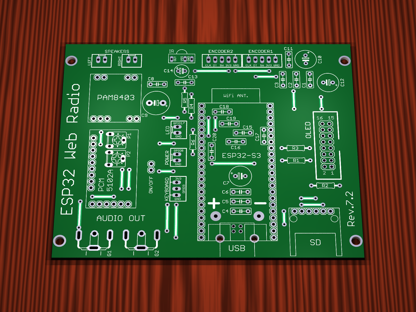
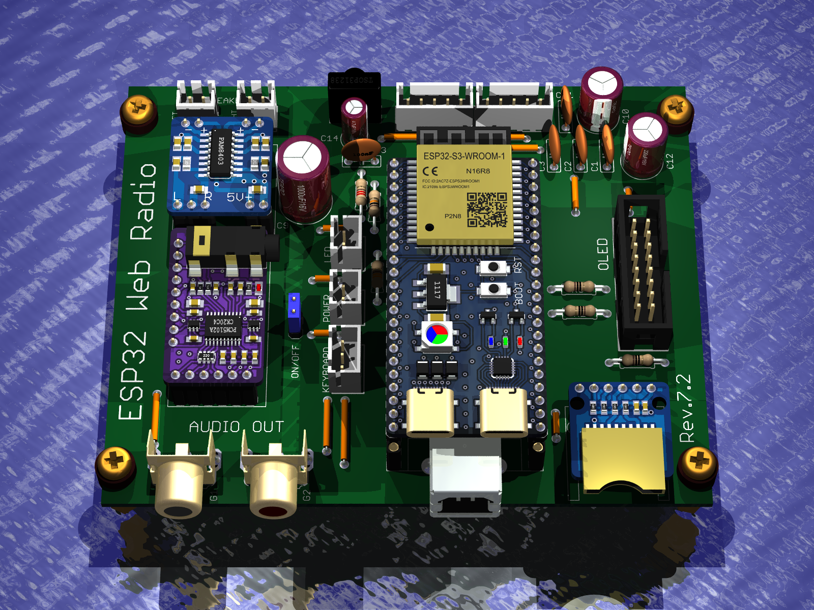
    Version Rev.7.2
    - Everything as in Rev.7.0
    - Added potentiometers for the audio signal to adjust the audio level at the input of the PAM8403 power amplifier


    Internet radio and audio file player on ESP32-S3 Internet radio and audio file player on ESP32-S3


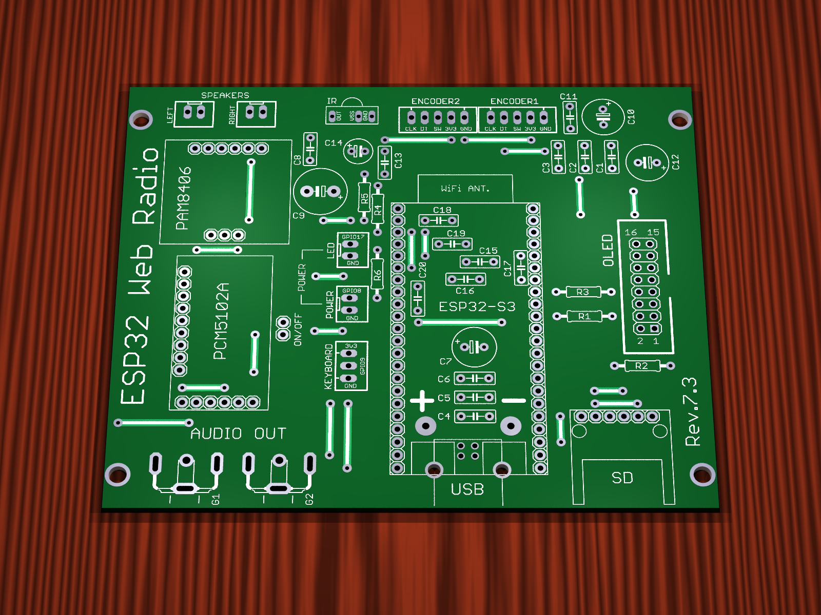
    Version Rev.7.3
    - Everything as in Rev.7.0
    - Power amplifier has been changed, PAM8403 has been removed and PAM8406 amplifier module has been used
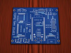
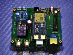
    Internet radio and audio file player on ESP32-S3 Internet radio and audio file player on ESP32-S3


    That would be the gerber files in the bulk archive attached.
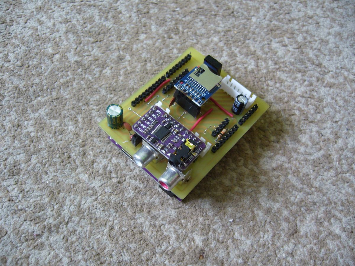
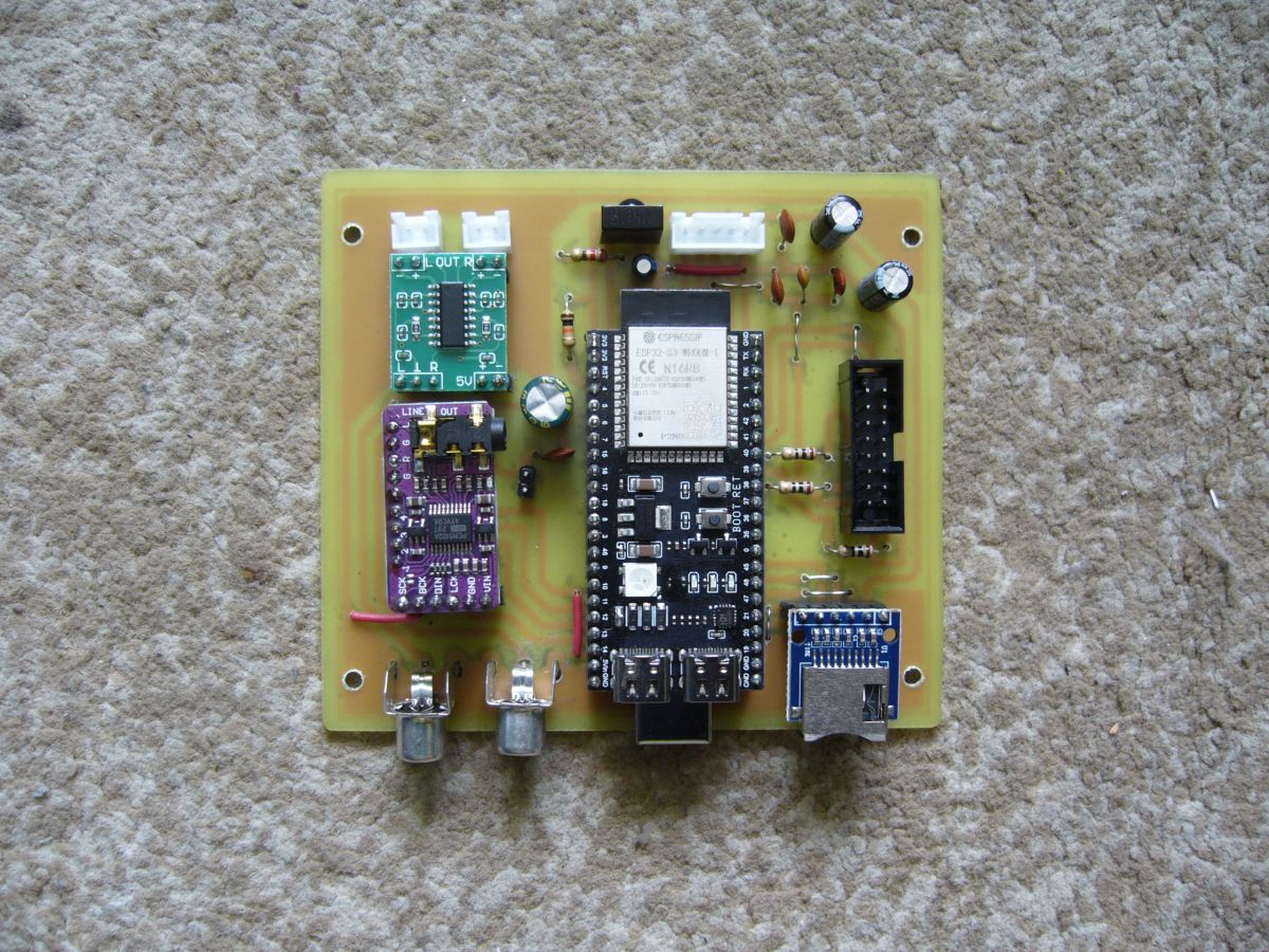
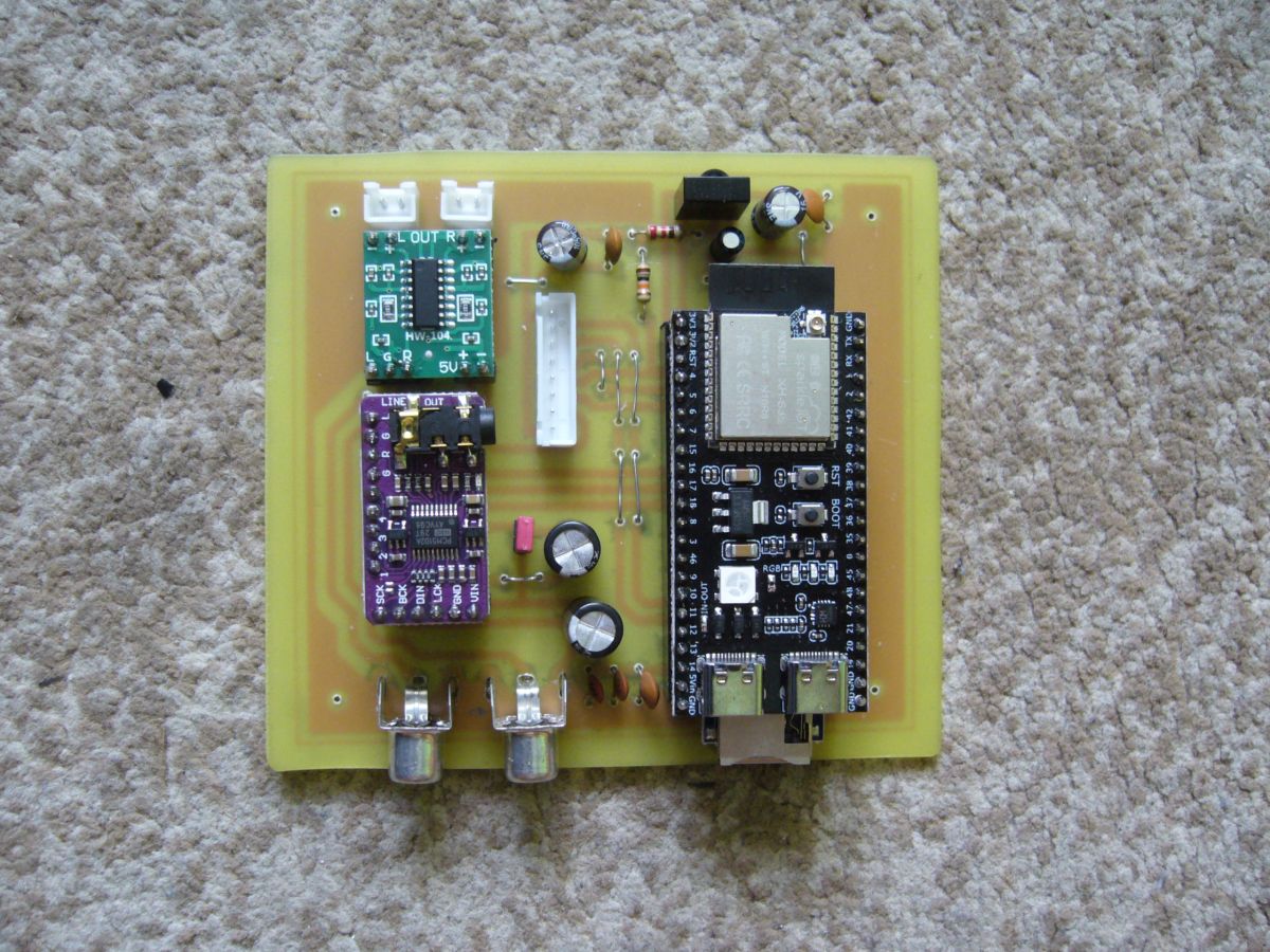
    Personally at my place I have the PCB versions Rev.1.0, Rev.2.0, Rev.3.0, Rev.4.0 running


    Internet radio and audio file player on ESP32-S3 Internet radio and audio file player on ESP32-S3
    Internet radio and audio file player on ESP32-S3 Internet radio and audio file player on ESP32-S3


    The other versions were created for the needs of electrode users, I did not personally assemble these versions.

    In all versions I included Eagle *.brd files
    No schematics, i.e. *.sch files, because when creating PCBs I work directly on *.brd files.

    Lists of elements for a given version are added in the form of an HTML file opened with a browser.

    Regards ....
    Attachments:
    • ESP32 WebRadio PCB.zip (113.63 MB) You must be logged in to download this attachment.
  • #2630 21890622
    Anonymous
    Level 1  
  • #2631 21890627
    ArturAVS
    Moderator
    Posts: 26140
    Help: 2295
    Rate: 7745
    Think about what you are writing about. I am leaving aside contempt and any disrespect.
  • #2632 21890636
    CodeBoy
    Level 33  
    Posts: 3272
    Help: 138
    Rate: 687
    >>21890622 If you ask the wrong questions you get the wrong answers.

    In Category 5 twisted pair (i.e. the Ethernet type cable used in TCP/IP) things are a bit different than in classic signal cables.

    🔌 What does transmission look like in a Cat5 cable?
    The cable has 4 pairs of twisted wires (8 conductors).
    The signal is transmitted as a so-called differential signal (balanced transmission).
    Each pair is:
    one wire: the "+" signal
    the other wire: the "-" signal (inverted)

    The receiver analyses the voltage difference between them, not the voltage relative to ground.

    ⚡ Is there a ground (GND)?

    👉 There is no classic signal ground like in audio or RS232 for example.

    Ethernet transmission (e.g. 100BASE-TX or 1000BASE-T) is:
    symmetrical
    galvanically separated (transformers in RJ45 ports)

    This means:

    the devices do not share a common signal ground
    signal "floats" relative to ground
    🧲 Why such a design?

    It offers several important advantages:

    resistance to EMI interference
    minimisation of crosstalk between pairs
    no problems with potential differences between devices
    🧩 And screen / physical ground?
    In UTP cables (most common) → no shield → no ground
    In FTP/STP cables:
    there is a shield (foil / braid)
    may be connected to earth
    but is not involved in data transmission
    🧠 Summary
    TCP/IP is only a protocol - physically Ethernet is at work here
    Transmission in Cat5 is a differential signal in pairs
    No classic signal ground
    Transformer separation = no direct electrical connection.
  • #2633 21890646
    Anonymous
    Level 1  
  • ADVERTISEMENT
  • #2634 21890651
    efi222
    Level 21  
    Posts: 733
    Help: 12
    Rate: 1191
    I don't understand where this argument about UTP/FTP and Ethernet transmission is coming from.
    My colleague kula350 clearly wrote that he used twisted pair as a shielded signal cable, where one wire from the pair works as a shield and is connected to the system ground. At least that is my understanding.
  • #2635 21890661
    CodeBoy
    Level 33  
    Posts: 3272
    Help: 138
    Rate: 687
    girowaty4 wrote:
    >>21890636 then you learn to read.
    Internet radio and audio file player on ESP32-S3
    I was sharing my knowledge and experience. And that's it. But for you guys, I think it's disruptive to pit on forms, so you got me.


    I was referring to "your" AI statement, you will always get the answer you need, a matter of the right prompt.
  • #2636 21892941
    ejcon
    Level 16  
    Posts: 277
    Help: 3
    Rate: 61
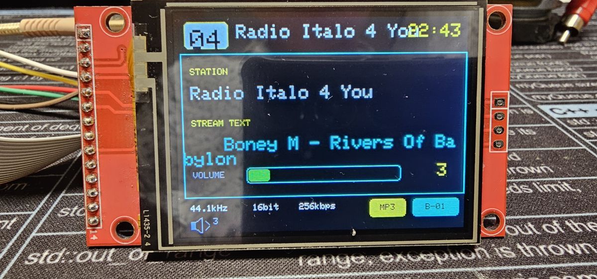
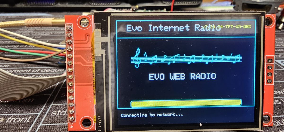
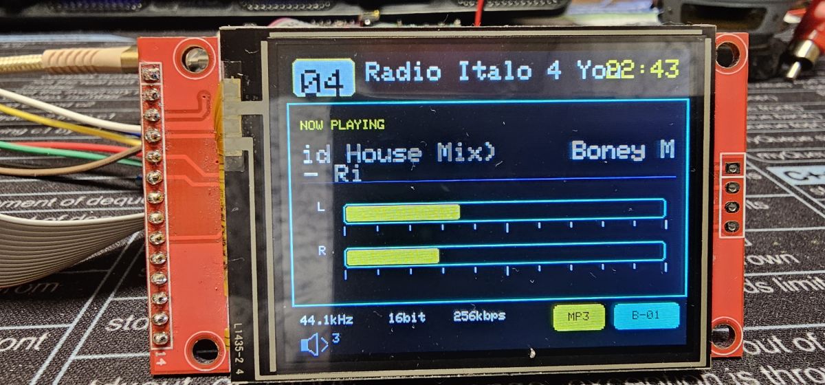
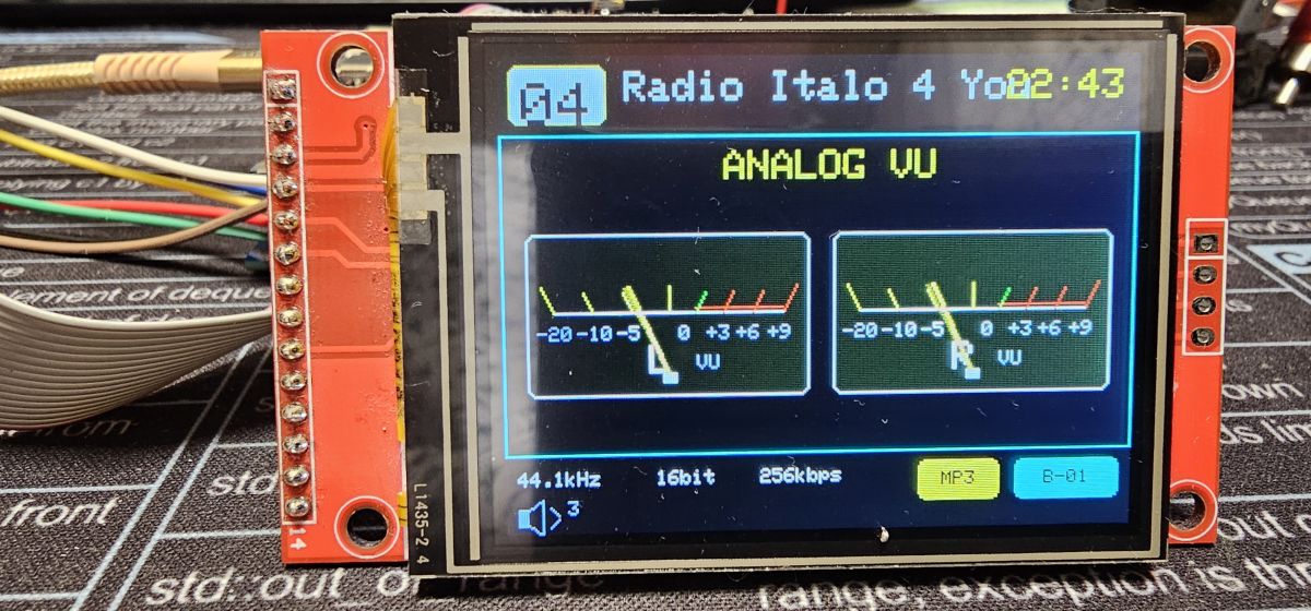
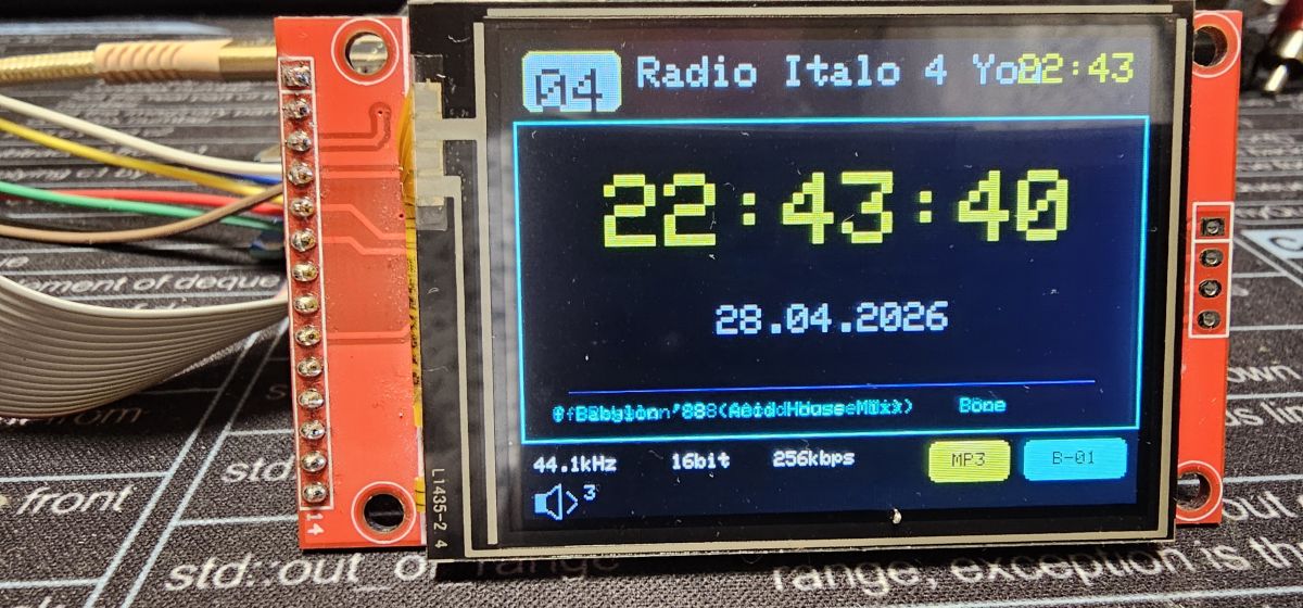
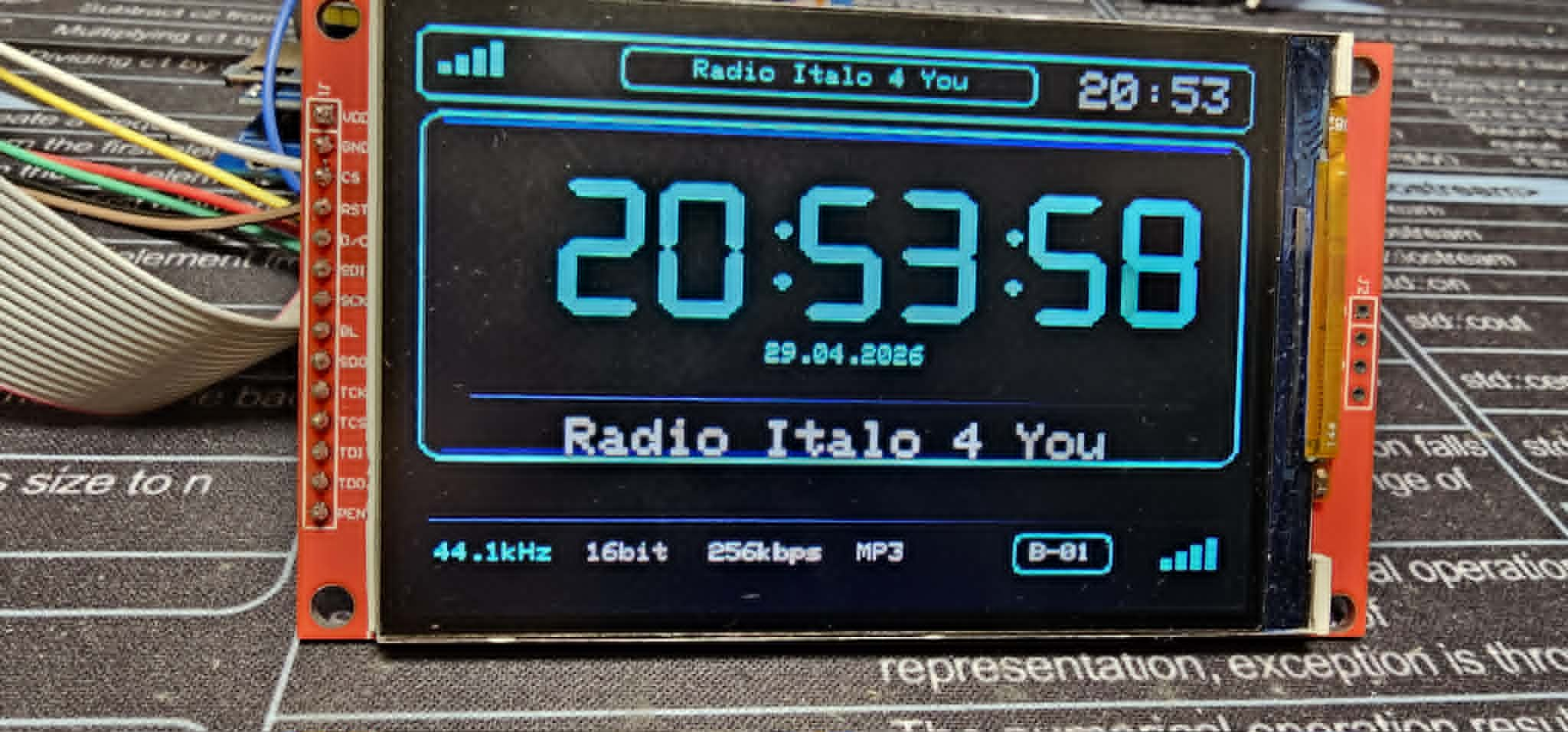
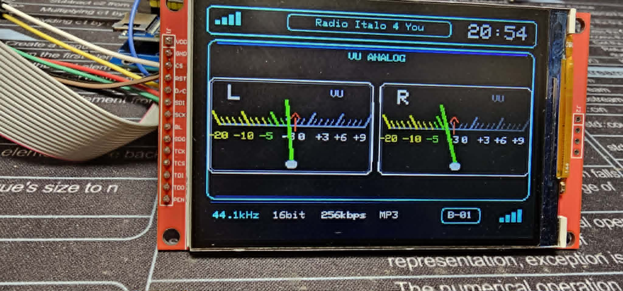
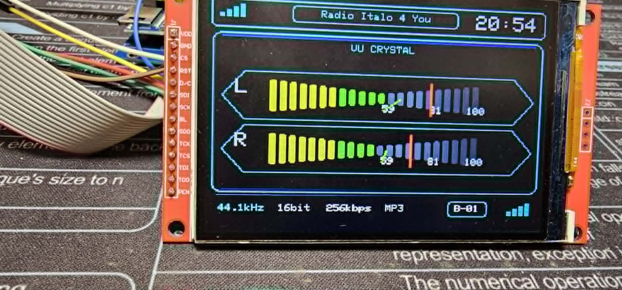
    We have EVO in colour so far very primitive but I encourage you to improve the panels from a visual point of view. Sofcik dedicated to the ILI9341 panel with the new LovyanGFX graphics bibiotech

    Internet radio and audio file player on ESP32-S3

    Internet radio and audio file player on ESP32-S3

    Internet radio and audio file player on ESP32-S3

    Internet radio and audio file player on ESP32-S3

    Internet radio and audio file player on ESP32-S3
    Attachments:
    • EVO_Radio_Arduino_ILI9341_V5_ORIGINAL.rar (90.38 KB) You must be logged in to download this attachment.
  • #2637 21892977
    efi222
    Level 21  
    Posts: 733
    Help: 12
    Rate: 1191
    ejcon wrote:
    new LovyanGFX graphics livery

    In my opinion this is a very good move in terms of graphics and TFT support.
    It is the most efficient library.
    It is based on the fast Tft_espi library, which is no longer being developed.
  • #2638 21893056
    DJCheester
    Level 28  
    Posts: 2072
    Help: 75
    Rate: 951
    DJCheester wrote:


    Version Rev.4.0
    - PCB version without SMD components
    - The jumpers are made on the top layer of the PCB as tracks, so they do not need to be mounted on the factory PCBs
    - PCB version without encoders
    - Audio output on Chinch sockets
    - TSOP31238 infrared receiver
    - Connector 8-pin for LCD display
    - 4-pin connector for SD card reader on display
    - Note: Do not use two card readers at the same time !!!
    - Audio amplifier PAM8403
    - Power supply USB printer socket
    - MAJSTER XXL software preload
    - Dimensions 98.04mm x 87.25mm
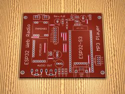

    Internet radio and audio file player on ESP32-S3 Internet radio and audio file player on ESP32-S3


    Did you keep the pinout from this PCB maybe ?

    Greetings ...
  • #2639 21893508
    ejcon
    Level 16  
    Posts: 277
    Help: 3
    Rate: 61
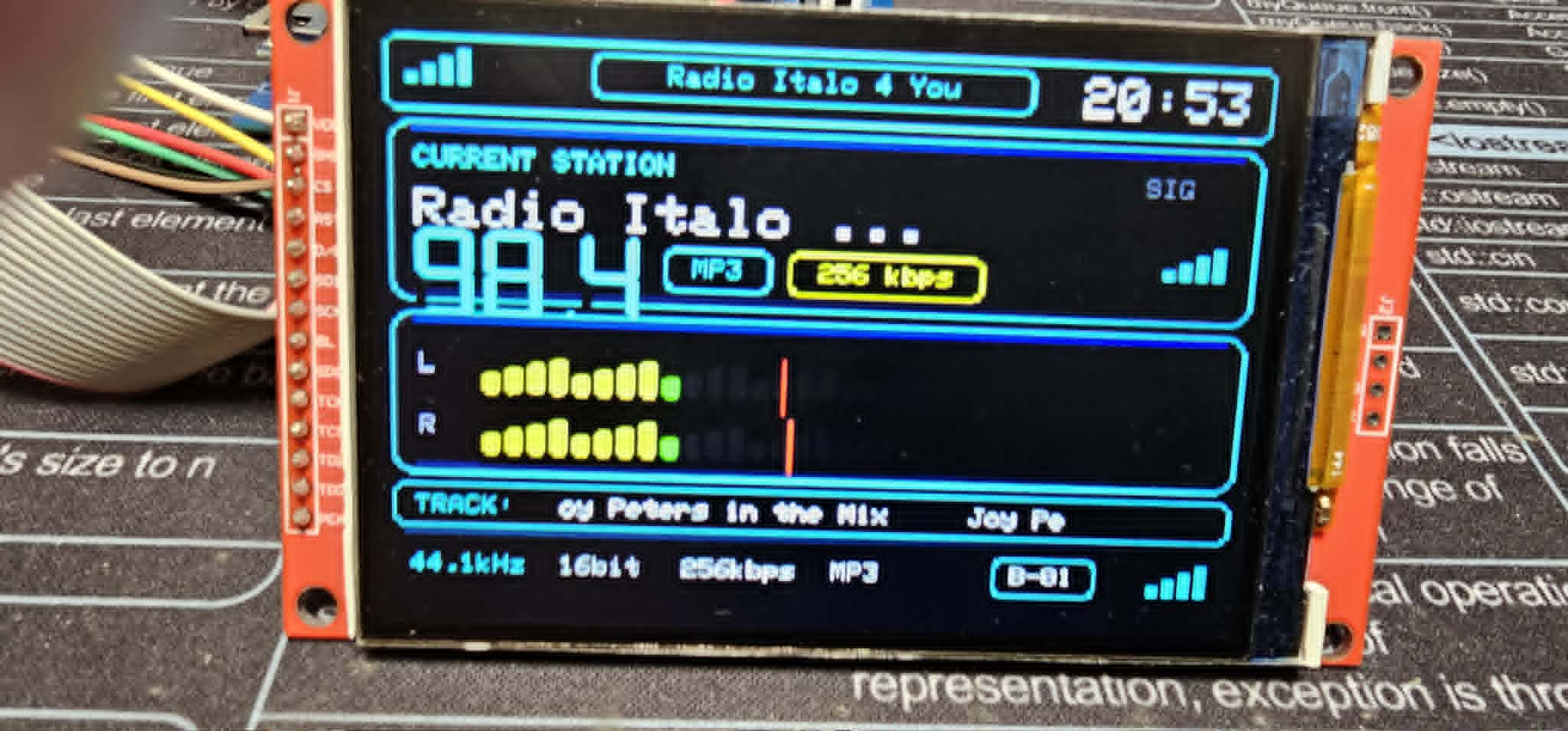
    I'll add a sofcik still warm for the ILI9488 EVO panel .
    Internet radio and audio file player on ESP32-S3


    Internet radio and audio file player on ESP32-S3


    Internet radio and audio file player on ESP32-S3


    Internet radio and audio file player on ESP32-S3

    ILI9488
    Connection to ESP32 S3 N16 R8 // -------------- OLED Display - pin definition -------------- #define SPI_MOSI_OLED 39 // MOSI pin (Master Out Slave In) for SPI OLED interface #define SPI_MISO_OLED -1 // no MISO for TFT display #define SPI_SCK_OLED 38 // SCK (Serial Clock) pin for SPI OLED interface #define CS_OLED -1 // CS residual screen to GND - dice on ILI9488 #define DC_OLED 40 // DC/RS screen on ILI9488 #define RESET_OLED 41 // RST screen on ILI9488
    Attachments:
    • EVO_Radio_Arduino_ILI9488_V7_VU_FIXED_27MHz_RECOMMENDED.zip (112.22 KB) You must be logged in to download this attachment.
  • #2640 21899630
    robgold
    Level 23  
    Posts: 722
    Help: 10
    Rate: 290
    Hello,
    i have uploaded to GitHub the new soft for Evo v3.20.14, Link

    changes:

    The most important issue is the compilation on the new core ESP version 3.3.8
    and new libraries for FLAC stations recompiled by me on ESP-IDF 5.5.4
    Latest Audio library 3.4.5q (commits 07.05.2026), yes I know this morning 3.4.6 came out, I will probably do an update when it rains again ;)
    Compilation of the whole thing as usual checked on Arduino (2.3.6) and on Platformio (pioarduino)

    The finished BIN files are for configurations:
    1x Encoder, OLED 3.12 SSD1322, FLAC support, AutoStorage function (the radio itself detects the presence of an SD card or switches to LittleFS memory)


    VOLUME and MUTE
    I have changed the volume handling range. It is now possible to set the value to zero (0) which results in the mute flag being engaged - mute.
    Makes it easier to completely mute the radio from a web page where there is no "mute" button.

    IR PILOT
    Corrected error of learning the power button via the web interface

    STATION SELECTION
    A solution has been proposed so that after selecting a station from the list, it does not have to be confirmed by pressing the encoder
    This is a configurable option in the menu. In the settings as: "Change station from list without click, default:O ff"

    OTHER
    VUmeter mode 3 - corrected value for right channel
    Improved configuration of the TI TAS amplifier
    Corrected positioning of the cursor in the station list when calling the list from the IR remote control (from the encoder it worked already correctly in the previous version)
    Improved display of station name when using the "Play from URL" function from a website
    Minor tidying up of the code


    P.S. Was anyone of you at HDM (Hardware Design Masterclasses #6) yesterday in Katowice? I had the opportunity to unknowingly meet someone ? ;)
📢 Listen (AI):

Topic summary

✨ The discussion centers on the development of an internet radio and audio file player based on the ESP32-S3-WROOM-1 module, featuring a custom-designed prototype PCB with OLED display and user controls including rotary encoders and buttons. Key challenges addressed include pin spacing discrepancies in the ESP32-S3 module footprint, integration of Wi-Fi connectivity with dynamic station list updates, and handling of Polish character encoding on the OLED display. The project uses Arduino IDE (version 2.3.2) with ESP-IDF support and requires enabling PSRAM. Audio playback supports MP3, AAC, and FLAC streams, with the ESP32-audioI2S library recommended over the incompatible Audio library. Users reported issues with SPI MISO pin assignment causing bootloader conflicts, resolved by reassigning MISO to pin 35. The project incorporates WiFiManager for network configuration, EEPROM and SD card storage for saving last played station and settings, and includes plans for tone control via an external KA2107 equalizer and a CS8673 amplifier module. Problems with encoder input stability and memory limitations for Bluetooth A2DP on ESP32-S3 were noted. The community suggested alternatives like KaRadio and ESP32-MiniWebRadio projects. Debugging tips include serial terminal logs for HTTP errors and flash memory erasure to resolve boot loops. The project is open-source on GitHub, encouraging forks and modifications. Additional features under development include browser-based updates, directory navigation, and potential audio recording to SD card.
Generated by the language model.
ADVERTISEMENT