logo elektroda
logo elektroda
X
logo elektroda

Internet radio and audio file player on ESP32-S3

MAJSTER XXL 101121 1230
ADVERTISEMENT
Treść została przetłumaczona polish » english Zobacz oryginalną wersję tematu
  • #631 21440984
    DJCheester
    Level 26  
    Yes duplicated I deleted the folder with the libraries installed q the system is temporary files folder Arduino15

    Greetings ...
  • ADVERTISEMENT
  • #632 21440989
    wirbud
    Level 13  
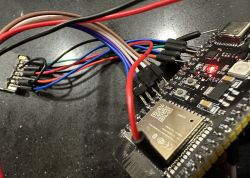
    >>21440976 you are right ! these wires are a massacre ! That's why I soldered most of them from the top to the ESP32 (KArta SD mini sits in the adapter and this one already on the solder.
    ESP32 with connected colorful wires on a black surface. .

    Added after 1 [hour] 7 [minutes]:

    Most of the problems solved - the jumper on the display for the SPI setting was illusory.... soldered and the screen no longer disappears.
    The occasional reset still remained. Maybe the case and short wires will improve that too. Thanks to everyone for their help Thank you Majster, for the super project and robgold for the great
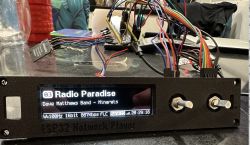
    screen lift and those notes ;-) For the housing also.... still a question about the switch button and SD port .... would you give a link of the pattern.

    ESP32 Network Player with display and wires.
  • ADVERTISEMENT
  • #633 21441107
    H3nry
    Level 32  
    Is there any chance to compile a soft under LCD 2x20 compatible with HD44780 ?
    I have a CU20029 Noritake very cool VFD still quite popular.
    I know, not much content fits but it is enough to make such a radio pleasing to the ear.
  • #634 21441335
    robgold
    Level 20  
    Welcome,

    I'm glad the enclosure has been useful. I have uploaded the latest version to GitHub with one encoder and a window for the IR receiver and IR LED. The whole thing is designed so that the power supply for the IR receiver and receiver LED can be "stolen" from the encoder pins. The window for the IR is printed from transparent PETG.
    I have also updated the front for the Hammond case.


    Front panel design for an enclosure with encoder and display slots .
    Design of ESP32 Network Player case with openings for display and buttons. .

    The switch for the case is: Link or or Link The former I have and there is a 3D design under it. The latter appears to have identical dimensions. I don't have it yet but when an order from TME is collected I will throw one in for testing.

    Card reader from Msalamon this -> Link .
    Display is -> Link
    Knob (fits a lot of different ones) I have one from Ali -> Link

    By the way Msalamon has sold all the OLED displays. I wonder how many people on this forum thread have bought an OLED from him for their radios ;) .

    I have uploaded the latest version of Evo 3.15 on GitHub - changes:
    - I made a Volume record after each change. If the radio comes out of the volume setting by itself or you confirm OK and adjust the volume then a record is made on the card. There is no display of this as it is the most 'time consuming' function and the save takes a fraction of a second. In addition, a bit of tidying up on the radio screen. I moved some fonts up, streamtittle by 1px higher. Hard to see :) .
  • ADVERTISEMENT
  • #635 21441380
    hevet
    Level 16  
    I managed to buy a display on Aliexpress recently for £42. The design is cool it's attracting interest.
  • #636 21441593
    DJCheester
    Level 26  
    Gentlemen, the radio is great, it works at my place and has been testing since yesterday, after adding an antenna from some tablet (the old one on the PCB I did not cut the path) there is a range signal strength shows excellent.

    I have paired the remote in the NEC standard and it works but there is one problem specifically with one button.

    But one by one I am using TSOP31238 which is 38kHz

    The schematic is as shown here

    https://botland.com.pl/img/art/inne/01047_3.jpg

    Except that I did not give a resistor pulling up the receiver output to 3.3V

    Power supply via a 220 ohm resistor and a 4.7uF electrolyte capacitor at the receiver itself.

    The remote control receives all programmed codes correctly.

    The problem is with one button the code in the sketch is 0009.

    The radio behaves as if it picks up this code on its own at random intervals and switches stations down in the list as this is what I have the button assigned to.

    It is only this one button that behaves like this, the rest don't start randomly, the remote doesn't transmit on its own (there is no shorted rubber band etc) I have removed the battery and it is the same.

    If I disconnect the IR receiver output from the ESP the radio works fine. So TSOP fault

    On the bootland schematic (admittedly a different receiver) there is a pull up resistor to 3.3v maybe add it and the 220 ohm resistor on the power supply reduce it to 100 ohms because I was using 220 ohms with an Arduino with 5V logic and here it is 3.3V

    Question what kind of receivers do you guys use - I mean the receiver itself on these Chinese modules - what type is it ?

    And if you could draw a diagram of that connection with resistor values, I would be grateful.

    From a logical point of view, what could be the reason that for other codes it works correctly and this 0009 starts up by itself. Are the bits as the receiver gives some more susceptible to interference ?

    Greetings....
  • #637 21441672
    robgold
    Level 20  
    @DJCheester
    IR receivers are very sensitive to various interferences. This is why shielding them is so important. I don't know what kind of receiver you have but ideally the whole thing should be in a metal "cage". Possibly tape it with copper tape like for EMC testing, wrap it with alu foil from sandwiches (being careful not to short circuit) of course this screen shorted to ground and a small window so it can "see" the remote control. The 200 or 100 Ohm resistor can be omitted altogether. On the other hand, insert an LED with a 1k resistor between the IR out and +3.3V and see if it sometimes flashes on its own. It's just a quick preview of what "junk" the receiver is catching. As I understand it you already have all this on the PCB. Because running the wires from the OLED close to the receiver will also affect it.

    @wirbud
    "The "rubbish" you are catching on the display is clearly cable problems. If the display loses power/communication for a moment, the SSD1322 chip inside also loses the configuration and initialisation that is sent to it. An EPS reset then helps, as initialisation only happens once at the beginning.
  • #638 21441874
    DJCheester
    Level 26  
    Hi well that's what I was thinking - tomorrow I will solder it off the PCB and put it on wires away from the board and ESP.

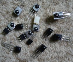
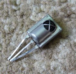
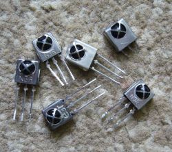
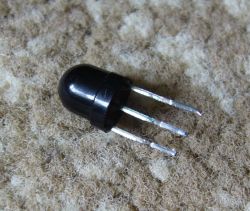
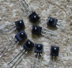
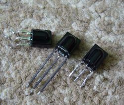
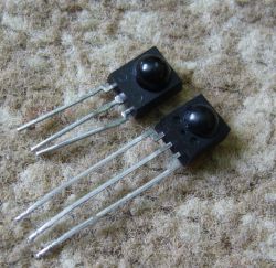
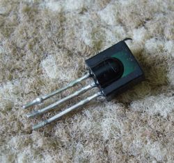
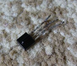
    Possibly I will use another one I have a lot of from disassembly the problem is the lack of descriptions and therefore interpretation of the pins

    Unless you know how to identify pins from such receivers....

    Several IR receivers with different casings and pin counts lying on a carpet.
    Three-legged metal electronic component lying on a carpet.
    Several metal infrared receivers with three pins lying on a carpet. .
    Three-pin sensor or IR receiver with a black housing, lying on a light surface. .
    Several electronic receivers with three legs on a carpeted surface. .
    Three electronic receivers with three pins each, placed on a carpet. .
    Two black infrared receivers on a fuzzy surface. .
    Three-pin IR receiver on a textured surface. .
    Close-up view of a black three-pin component lying on a carpet-like surface. .

    I would appreciate your help in identifying the type/pinout of the receivers ??

    Greetings ...
  • #639 21442184
    wirbud
    Level 13  
    Probably a lamer question - If I version 3.15 with one encoder - (Encoder 1 - uzwyany for the player) wywalać - do I not connect this encoder or do I have to comment it out in the code. It seems to me that when I didn't connect it, the screen went silly and seemed to "generate change signals" all the time. Is this possible? Did I miss it or is it the result of other deficiencies in the testing phase?
  • #640 21442188
    hevet
    Level 16  
    Enter -1 values in the pin numbers otherwise there will be the circuses you have written.
  • #641 21442284
    robgold
    Level 20  
    Yes, you need to disable it in the code because that library to handle that button in the encoder I feel like doesn't set the pull-ups correctly. Comment out or on each line give a 10k to 100k resistor and up to 3.3V.

    This leaves Encoder 2 not 1.
  • #642 21442966
    DJCheester
    Level 26  
    Hello how to do this exactly - just comment out the lines

    Code: Arduino
    Log in, to see the code


    Alternatively, where do you give it a value of -1 ?

    Maybe with me it is also partly the result of not having the encoders plugged in, I will plug them in today.

    Acha buddy robgold, one more thing, on your diagram the 4x4.7k resistors are for the master keypad, I don't have one, I only have the socket and the resistors mounted.

    Tell me, on the ESP lines they act as a voltage divider setting half the supply voltage value or is it supposed to work like that ?

    Greetings....

    Added after 1 [hours] 28 [minutes]:

    Hello again - with the receivers it has cleared up, I downloaded quite a few pdfs and connected a few unfortunately the problem is the same, but the problem however turns out to be what a colleague wrote earlier i.e. unconnected encoders.

    At the time I wrote that it was the IR receiver, but then I didn't take a look at the serial monitor and when I disconnected the IR receiver the hardware just worked fine, which misled me.

    Today, I've run the radio again for a while without the IR receiver and it turned out that the bank goes down by itself. I've inserted my encoder declaration before - I've swapped pins 10 and 11 on the PCB so don't look at it.

    Here is the log from today

    Code: Text
    Log in, to see the code


    What is the problem ?

    Could it be that the encoders that they are not connected ?

    I am about to solder them and will see if I can rework the declaration so that it is possible to listen to the radio only from the remote control.

    Greetings ....
  • #643 21443104
    hevet
    Level 16  
    Try
    
    // Enkoder 1 - uzywany dla odtwarzacza
    #define CLK_PIN1 -1              // Podłączenie z pinu 6 do CLK na enkoderze prawym
    #define DT_PIN1 -1               // Podłączenie z pinu 5 do DT na enkoderze prawym
    #define SW_PIN1 -1               // Podłączenie z pinu 4 do SW na enkoderze prawym (przycisk)
    
    // Enkoder 2 - uzywany dla radia
    #define CLK_PIN2 -1             // Podłączenie z pinu 10 do CLK na enkoderze
    #define DT_PIN2 -1              // Podłączenie z pinu 11 do DT na enkoderze lewym
    #define SW_PIN2 -1              // Podłączenie z pinu 1 do SW na enkoderze lewym (przycisk)
    .
  • #644 21443348
    tytka
    Level 22  
    robgold wrote:
    IR receivers are very sensitive to various interferences. This is why shielding them is so important. I don't know what kind of receiver you have, but ideally the whole thing should be in a metal "cage". Possibly tape it with copper tape like for EMC tests, wrap it with alu foil from sandwiches (being careful not to short circuit) of course this screen shorted to ground and a small window to "see" the remote control.
    .

    Somehow I have never used any extra screens on IR receivers, and I have never had any problems with their operation without such screens.

    DJCheester wrote:
    Unless you know how to identify the pins from such receivers...
    .

    Such integrated receivers, often have a symbol on the housing (e.g.: 4838, 2240 etc. ), so you can check their "pinology" in the data sheet. (To get the full symbol add the prefix: TSOP).
  • #645 21443705
    DJCheester
    Level 26  
    Hello

    Soldering and plugging in took care of the issue of running random stations down the list, it turned out that the encoders or rather the lack of them was the problem.

    The radio has been playing for half a day now and on the serial monitor nothing unnecessary is caught.

    So encoders are needed at start-up - I confirm.

    I haven't tried defining them at -1 - maybe I'll try at the next compilation.

    Well finally the radio works as I wanted ;) .

    Case of receiver I've plugged in 3 types from what I've shown above pictures and the best in the sense of signal catching and distance have the big ones what I've designed in PCB that is TSOP31238.

    Thanks to all greetings ...
  • #646 21443723
    tytka
    Level 22  
    DJCheester wrote:
    So encoders are needed at launch - I confirm

    In terms of accuracy, it is not the encoders that are needed here. The problem is with the pull-up resistors (pulling up the ESP ports to power), which you don't have on the motherboard, only on the encoder board.
  • #647 21443876
    hevet
    Level 16  
    @robgold how do I make the display dim by default when I start the radio?

    u8g2.sendF("ca", 0xC7, displayBrightness); do I set 0x15 in this line instead of 0xC7?
  • ADVERTISEMENT
  • #648 21443990
    MAJSTER XXL
    Level 29  
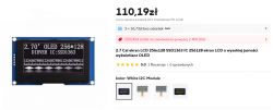
    And I already know I'll be making my v3 version based on a 256x128 OLED display, I've been looking for some larger size but there's not much to choose from. I got a bit caught up because I didn't notice and ordered a 4 PIN, so it will probably be via I2C. There will be an opportunity to tie mine and @robgold's screen inserts together more and expand the number of lines and useful info.


    2.7-inch OLED display 256x128 with price and description. .
  • #649 21443995
    hevet
    Level 16  
    Maybe you will do version 3 on a colour display?
  • #650 21444163
    robgold
    Level 20  
    @hevet

    In the variable declaration at the beginning, change:

    Code: C / C++
    Log in, to see the code
    .

    This way you won't lose the ability to change this from the remote control and just start with a dimmed display. The adjustment range of this variable 0-15. Theoretically you can still bump up the brightness with other registers but this is an OLED. Any such boosting will reduce its lifespan.

    @tytka
    Nowadays, manufacturers of IR receivers "go to great lengths" to ensure that there are adequate IR filters already in the casing plus good shielding. Until a few years ago, one encountered designs based on ordinary IR receiver diodes. These were mini Faraday cages with a window to allow the "light" of the remote control to enter. Therefore, if there are problems with reception (assuming the code in the uC is working correctly), the first attempt is to separate it from visible light for a while plus shielding such a receiver.

    @MAJSTER XXL
    Beautiful art :) Hm.... Station number to the very top, bank too, I'd get back 26 characters for the station name. Plus the watch at the top, audio info at the bottom. Eh...pity there isn't something like 512x64. I guess I grew up in the era of 'tower deck' audio equipment I like the unit to be low and wide. This new OLED is 50mm which means an enclosure of 60mm minimum. It will be a challenge to insert it nicely somehow. Do you have any enclosure in mind ?
    You can see that the u8g2 library only got support for this SSD 1363 driver a month ago: Link .
  • #651 21444191
    hevet
    Level 16  
    @robgold I have changed, but it still runs at maximum brightness.
  • #652 21444201
    robgold
    Level 20  
    @hevet

    You're right, the command won't send itself. Put in the void setup() section:
    Code: C / C++
    Log in, to see the code
    .

    The library always starts with the maximum brightness setting.
  • #653 21444237
    hevet
    Level 16  
    @robgold thanks it works.

    Changing to
    uint8_t displayBrightness = 0; // Display brightness;

    and u8g2.sendF("ca", 0xC7, displayBrightness);

    Preferably at the end of void setup(); as long as after initialising the display.
  • #654 21444251
    robgold
    Level 20  
    >>21444237 Preferably in the section before the "else" from no connection. Then if there is no WiFi the display will not dim.

    Code: C / C++
    Log in, to see the code
    .

    I have put this setting into the code. Subsequent updates will only allow manipulation of the variable.
  • #655 21445509
    DJCheester
    Level 26  
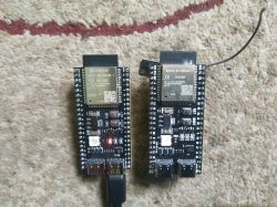
    Gentlemen I bought another ESP from Ali and I have to say that it is like the original, there is the espressif logo to the different shape of the ESP module this metal heatsink and antenna and the range is super without combining.

    I attach a photo of both for comparison.


    Two ESP32 modules on a carpet, one with Espressif logo. .

    So the bubble bought in Poland and the one with the logo from china super.

    Greetings ...
  • #656 21446427
    Szaryczlowiek83
    Level 7  
    Such a question for experts on the subject.
    What do you say about such a board for the radio? Link .
    Because if I understand correctly, such a board covers most of the
  • #657 21446433
    hevet
    Level 16  
    But what radio do you want to use it for?
  • #658 21446440
    DJCheester
    Level 26  
    The colleague is probably looking for a ready-to-use PCB assembled to just "inject" the soft and that's it.

    For our radio you would have to create a PCB from the modules used in the project.

    If you are interested in PCBs, I have already made files available, so that you could solder one yourself, on ready modules used in the project.

    The radio on my version of PCB is assembled and running so the circuits are correct and match the pin declarations in the softwares from this topic.

    Regards...
  • #659 21446481
    tytka
    Level 22  
    Szaryczlowiek83 wrote:
    Because, if I'm getting it right, that kind of tile covers most


    Not quite.
    For example, there is no DAC on it. In addition, this is not the ESP version of the S3, so the radio will not work on this.

    On the other hand, if you would like to buy a ready-made "all in one" board for building an internet radio, but a different one (not this one), then look around for something like this: Link .
    On such a board you can fire up YoRadio with support for reading files from a uSD card. I have done this without any problems.
  • #660 21447078
    robgold
    Level 20  
    Welcome,

    For those using the Evo version of the radio. Today there has been an update to ALL the banks on GitHub. I have removed the links with stations that don't work. Some banks have been arranged thematically, some have very few stations at the moment. This is due to the fact that almost half of the stations were either repeating themselves or no longer exist.

    Bank01 - a mix of different stations in my 'favourites' compilation.
    Bank02 - remained largely intact, a mix of different stations
    Bank03 - Polish regional stations, Radio Warsaw, Radio Katowice, Radio Gdańsk, Radio Opole, etc.
    Bank04 - a collection of American radio 181.FM rounded off at the end by "Life Radio" + Party Vibe
    Bank05 - all thematic RMF stations
    Bank06 - relaxation music, Smooth Jazz, Lounge, Chill, bank supplemented at the end by American 113.FM stations
    Bank07 - all Polish Radio streams complemented by Polish Radio.FM Chicago, Radio Pogoda, Radio RDC and about 20 stations with classical music
    Bank08 - mix of various stations
    Bank09 - mix of different stations
    Bank10 - mix of various stations
    Bank11 - mix of various stations with emphasis on Polish stations
    Bank12 - Rock, Hard Rock, heavy sounds
    Bank13 - Mix of various stations
    Bank14 - Mix of various stations
    Bank15 - Mix of various stations
    Bank16 - Mix of various stations

    If there are any errors with the station names, please let me know. Sometimes the "excel"-format with macros that I wrote for automatic file generation plays tricks.

Topic summary

The discussion revolves around building an internet radio and audio file player using the ESP32-S3 microcontroller. The project includes features such as an OLED display, Wi-Fi connectivity, and audio playback capabilities. Users share their experiences with hardware setup, including issues with pin configurations, library compatibility, and troubleshooting compilation errors in the Arduino IDE. Suggestions for libraries, such as ESP32-audioI2S and WiFiManager, are provided to enhance functionality. Participants also discuss the importance of proper wiring, capacitor usage for encoders, and the potential for adding features like DLNA support and a web management interface for radio station management. Several users report on their progress, share code snippets, and offer solutions to common problems encountered during development.
Summary generated by the language model.
ADVERTISEMENT