logo elektroda
logo elektroda
X
logo elektroda

Internet radio and audio file player on ESP32-S3

MAJSTER XXL 109593 1253
ADVERTISEMENT
Treść została przetłumaczona polish » english Zobacz oryginalną wersję tematu
  • #571 21436496
    Slawek K.
    Level 35  
    DJCheester wrote:
    .

    Have you thought about adding the option to listen to songs e.g. from your phone ?

    For example mode radio/sdmp3/bt

    Greetings...
    .
    ESP32-S3 does not support A2DP because BLE, so it is not possible to transmit audio this way.
  • ADVERTISEMENT
  • #572 21436502
    wirbud
    Level 13  
    >>21436480 I read somewhere that it is not possible to use the BT built into the ESP32 for our purposes. For this reason, I used the Bluetooth 4.1 module KCX_BT_EMITTER (as Wolle backs - schreibfaul1). I also have a test behind me with a couple of dongls - and I liked this one: https://allegro.pl/oferta/adapter-dzwieku-blu...iter-samochodowy-pc-audio-aux-usb-14469643465 And this one is even better - because it remembers the last headphones and connects to them without pairing. https://allegro.pl/oferta/odbiornik-dzwieku-adapter-bluetooth-usb-aux-11481452350
  • #573 21436550
    robgold
    Level 20  
    A colleague has already written back. Unfortunately, the ESP does not support A2DP because it only has BLE 5.0 and it has no profiles. And BLE itself (in this version) is not very suitable for continuous streaming. Unfortunately it is not LE Audio 5.2

    Regarding Volume saving, yes, I can implement such a thing in Evo 3.15. The question is when to save this level ? Always or only after ENT/OK confirmation ? The idea is to minimise the write operations on the card. Otherwise every change will generate a write.
  • ADVERTISEMENT
  • #574 21436559
    ArturAVS
    Moderator
    And can't you make it so that it saves the current settings when the power is switched off?
  • #575 21436566
    robgold
    Level 20  
    The power is physically cut off today, so there is no time for this saving. There would have to be "power management" implemented for the module to save and only cut off the power.
  • ADVERTISEMENT
  • #576 21436676
    khoam
    Level 42  
    robgold wrote:
    Always or only after ENT/OK approval ? It is about minimising write operations on the card.
    .
    And why should this information be stored on the card? Isn't it simpler and much faster in flash?
  • #577 21436759
    boloteam 2.0
    Level 10  
    To clarify the A2DP support issue - the ESP32 supports A2DP.
  • #578 21436765
    robgold
    Level 20  
    It seems to me that it is just as easy to write write functions here or here. Flash emulating eeprom or nvs also has a life span of 100k cycles as it is still the same memory. The master took the approach that we keep the settings on the card as separate txt files, which makes it easy to read everything on the computer. I wouldn't want to do a mix now, some settings here, some here.
  • #579 21436773
    DJCheester
    Level 26  
    Gentlemen, the recording can be made on the card every time (after all, you don't set it up all the time), say after a change, wait a few seconds so that you can set it up quietly and then record even a minute after setting it.

    If the radio is kept in the kitchen, the knob or remote control will be moved once or twice a day.

    As for the casing, I was thinking of dismantling such a Chinese to make a nice casing.

    https://allegro.pl/oferta/radio-kuchenne-retr...-przenosne-mini-jack-antena-solar-16101659743

    Greetings...
  • #580 21436786
    CodeBoy
    Level 33  
    robgold wrote:
    Welcome,


    Custom ADC: .
    I managed to obtain an old Sony ST-120 tuner as a "donor" for conversion. Consequently, the need arose to add keyboard support. As a test I built a matrix resistive keyboard based on reading from ADC and I can tell you that it works very stable. If there are problems, I will switch to PCF8575. On the schematic there is a place to connect the i2c keyboard. In the INO file the keyboard is disabled. You have to disable the comment in lines 3893-3897. The schematic of the keyboard and the resistor values can be seen in the pictures.

    The keyboard has a specific connection matrix resulting directly from the solution that is in this Sony. In general, old Sony tuners are very cool because they have a minimum of buttons and a large knob under which either Sony already mounted a knob/button +/- for tuning or an encoder. So the conversion is simple. If anyone wants I can provide ready-made files for conversion under the OLED 3.12 display and IR receiver. The prices of these tuners as I looked are in the range of 80-100PLN and we gain a housing and a ready-made power supply 12V, 24V. So a simple 3.3V inverter solves the problem.
    .

    Hi,
    I'm 99% going to be making one in such an enclosure too, I also have such an "enclosure", so as soon as I have time I'll get back to you :)
  • #581 21436803
    MAJSTER XXL
    Level 29  
    I used to think about storing the volume of each station from each bank as a separate setting. There could be two solutions, the first is in the station name just after the phrase e.g. ....... Bank 11 Station 66897e998888cd add a digit from 0-9 in a fixed position and this would be a user-writable volume parameter that would set the volumeSet function to a range from 11 to 20. This would be a solution where we upload this data to github and when the bank is pulled/updated it would be read by the ESP32 from that particular position in the array. This would require users to keep an eye on the entry at that fixed position in the array for the correct setting, and would require links from the bank's own repository on github. The other option is to keep these volume settings in separate files on the board - which is probably much simpler to implement for those who don't have their own profile on github and use the shared bank files.
    Alternatively, you could try running an AGC function - some kind of automatic volume control - but this would be a global operation, without individual settings for each station.
  • ADVERTISEMENT
  • #582 21436816
    DJCheester
    Level 26  
    The differences in the stations are considerable, i.e. in volume, but here it is mainly a matter of the radio playing more quietly at the beginning, then you can make it louder, from what I quickly looked at the script there is a declaration of the initial value and you can change it and that's it, but it would be better if the information about the volume status was stored locally, typically on the card. Often I find this would not be the case the card has a large number of read and write times and if anything happens to replace the card with another one it is not a fortune either.

    Regards...
  • #583 21436981
    robgold
    Level 20  
    @DJCheester

    I'll throw in a feature where it will be possible to confirm in the "Volume" menu with the ENT/OK button on the remote control to save the set value as the start value.
    Saving the last value non-stop seems to me not very safe/practical because someone listening loudly on a given day turns the radio off and turning it on the next day might freak out. At the most, we will later modify, rework if this does not work.
  • #584 21437003
    DJCheester
    Level 26  
    I think it will be ok 😀

    It's at the next update at ease.

    Thanks and best regards...
  • #585 21437187
    robgold
    Level 20  
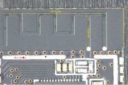
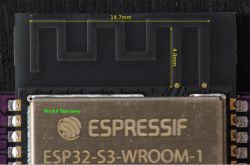
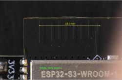
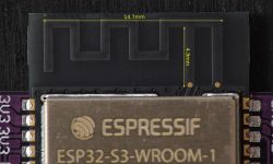
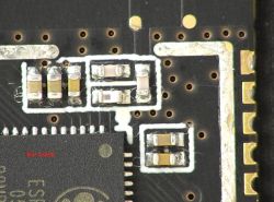
    Out of curiosity "nature", I threw three ESP modules on the digital microscope today.
    One with a black PCB - working, one with a purple PCB and a "poor 3V3 regulator" - working and the one with black PCB not working.
    This black working module has a completely different WiFi antenna. I'm tempted to hook up to this non-working module with a VNA analyser and see where it 'flies out' on the Smith chart. Unfortunately in the datasheet the manufacturer does not give any reference layout or component values to verify this. The web is full of tutorials and it seems as if it is all a copy of the same solution.

    In the last link "ESP32 S3 Hardware Design Guidelines" there is one layout shown and interestingly enough the module that works best (black PCB different atenna) has just such a layout. The rest is some kind of "Chinese creativity".

    Some links:
    Link 1 .
    Link 2 - TI guide
    Link 3 - ESP Hardware Design Guidelines

    In terms of the RGB diode, in the devKit ESP32 S3 it is zipped to GPIO48. We have an SD card on this port so it will not go off by itself even after a reset.
    You have to help it by cutting the jumper :) .


    Close-up of a PCB module with electronic components. .
    Close-up of a black PCB with markings Nie działa and dimensions 14.5 mm and 5 mm. .
    Close-up of ESP32-S3-WROOM-1 module with visible antenna. .
    Close-up of an ESP32-S3-WROOM-1 module with black PCB and antenna marking. .
    ESP32-S3-WROOM-1 module on purple PCB with visible antenna. .
  • #586 21437328
    simw
    Level 27  
    robgold wrote:
    From "nature" trivia, I put three ESP modules on a digital microscope today.
    .
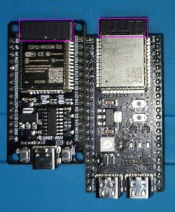
    I didn't have a microscope, but I have a similar case. 2 Wroom-32D modules not working properly, modules not responding, ripping streams etc. Checked on yoRadio.
    Plus 2 modules from ESP32S3 on which everything works as expected.
    Photo not of very good quality, but you can see that the antenna in the non-working one is completely different.


    Comparison of two electronic modules, ESP32-WROOM-32D and ESP32S3, on a blue background. .
  • #587 21437430
    CodeBoy
    Level 33  
    Yesterday I read on the Commodore group (they build there various wonders for Amiga etc) that there can also be "bugs" in the software and not everything works on everything, not even the antennas but also the processors can work "differently" So not only the antenna is a problem. I have now ordered 2 units from Ali and we will see what arrives. On the other hand, maybe it would be worth writing some proven source of this ESP at least for the time being, because apparently these are not expensive modules, but again, collecting 10 damaged - not fully operational - modules is a bit of a waste of space and $
  • #588 21437573
    khoam
    Level 42  
    simw wrote:
    I didn't have a microscope, but I have a similar case. 2 Wroom-32D modules not working properly, modules not responding, ripping streams etc.
    .
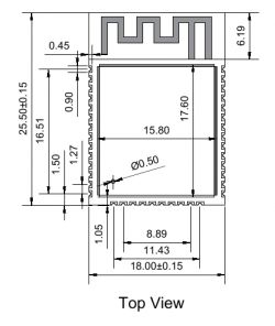
    From the picture posted, it appears that this is 99% fake (the one on the left). Anyway, Espressif has not been producing ESP32-WROOM-32D modules for some time and recommends ESP32-WROOM-32E instead. As for the pcb antenna on this module, it should be, as in the image below (from the manufacturer's documentation):

    Espressif ESP32-WROOM-32D module with visible model marking and PCB antenna elements.
    .
    Diagram of an ESP32-WROOM-32D module with dimensions. .


    I avoid using pcb antennas on ESP32 circuits and use an external antenna connected to the IPEX socket. In my experience, even a "piece of wire" as an external antenna is better than a pcb antenna. There are ESP32-S3-DevKitC modules equipped with ESP32-S3-WROOM-1U chips to work with an external antenna.
  • #589 21437591
    miroskop
    Level 23  
    It appears that the fakes do not have the 'Espressif' logo and lettering. All in all, this is logical (?)
  • #590 21437756
    khoam
    Level 42  
    miroskop wrote:
    It appears that the fakes do not have the "Espressif" logo and lettering.
    .
    Or the wrong FCC identifier. It should be: 2AC7Z .
    If it is different, you can try to find the "manufacturer" in the database https://www.fcc.gov/oet/ea/fccid
    For example, I have a couple of chips from FCC 2ATPO and their manufacturer is AI Thinker (supposedly a legitimate OEM) - they are "economical" ;)
  • #591 21438192
    robgold
    Level 20  
    @koham

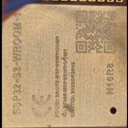
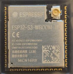
    And what would you say to the fact that I have a module from the FCC 2AC7Z but without the Espressif logo ? In addition, those modules that have the logo compared to a module from TME ( theoretically from legal distribution) have a much lower quality engraving. I think that they already counterfeit everything today and even have no qualms about sending fakes with the correct FCC and logo to the EU market.

    I agree that there is a better chance of an original with the logo and correct FCC. As well as the fact that modules with external antenna are more reliable because, as you can see from my microscope measurements, subsequent copies from film copies or scans cause the antennas to diverge and probably no longer have a perfect fit with the components that have been soldered into the filter. Therefore a piece of wire plugged into the antenna socket, even a moderately matched one, may work better than this simple antenna on a laminate, even though it is only 2.4GHz and nowadays you can do 76GHz without Roger-type materials.


    Close-up of FCC printing on module 2AC7Z without Espressif logo. .
    Close-up of an ESP32-WROOM module with engraved text and a QR code.


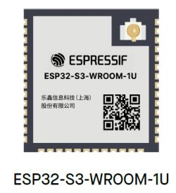
    I wouldn't suggest the renders in the Espressif instructions either. In the official instructions the antenna connector has the render turned 90st relative to the physical module (TME purchase)


    ESP32-S3-WROOM-1U module from Espressif with visible logo, model name, and QR code. .
    ESP32-S3-WROOM-1U module with Espressif logo and certification details on casing.
  • #592 21438311
    Lechuuu
    Level 13  
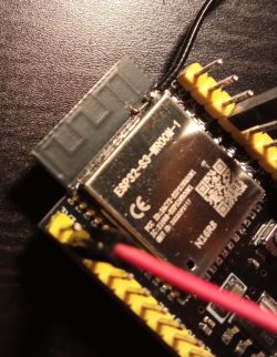
    I was also going through a coverage problem on the ESP32-S3 2 days ago.... It was ripping the stream and disconnecting the network every now and then.... I thought I had come across a faulty unit. I checked on x-ray that all the components were soldered and found nothing - everything OK. I decided to cut the path from the original antenna on the PCB and added an external one. Now the range is great, everything is working fine :) Something has screwed up with this antenna on the PCB - also cut and solder the external antenna.
    Close-up of ESP32-S3 board with an externally soldered antenna.
  • #593 21438341
    simw
    Level 27  
    For this, the ESP32-S3 Supermini module has no communication problems at all.
    Interestingly, the rssi 'sensitivity' value reported by yoRadio is -70dBm for this module, and therefore not working -59.

    ESP32-S3 Supermini module connected to a breadboard with an OLED display showing the text LATIN LOVER - CAS. .
  • #594 21438351
    khoam
    Level 42  
    >>21438341 .
    There is a ceramic antenna out there and they are slightly better than PCB antennas.
  • #595 21438362
    robgold
    Level 20  
    This super mini has a ready integrated antenna. A completely different story. A much more stable solution but expensive. The parameters of those on the PCB depend on everything from the thickness of the pre-preg used to manufacture the PCB to the thickness of the solder-mask paint, etc. This is suitable for development provided you have an Access Point under your nose.

    @Lechuuu I'm all for it. I think it's the easiest solution even if we don't perfectly shoot with the fit. It's not CB radio that the tip will get hot from reflections, the powers are small.
  • #596 21438469
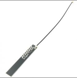
    DJCheester
    Level 26  
    Hello where to get such an antenna ?
  • #597 21438471
    miroskop
    Level 23  
    @Lechuuu I have a question: did you cut only this inner (left) path or both?
    Edit: however, through the magnifying glass I can see that this right path does not go under the screen. There was no question.
  • #598 21438508
    robgold
    Level 20  
    This right path is the ground. The left one is the fader for the antenna.

    Illustration of PCB trace layout with a green right-hand ground trace and left hand antenna feed trace. .
  • #599 21438563
    Lechuuu
    Level 13  
    @DJCheester I just happen to have one like the one in the picture from allegro (type in: wifi esp antenna)
    Black WiFi antenna for ESP with cable and connector.

    @microscope to cut only the left path, the right path is ground and is connected to the shield. It is important to solder the wire as in my picture, that is, the wire strand is to be to the left path.
  • #600 21438567
    MAJSTER XXL
    Level 29  
    I see that the antenna theme has developed, and in the meantime I'm throwing in an add-on that saves the volume settings of each station from each bank to an appropriate file where these saved settings are kept. The volume settings are saved to the file on an ongoing basis without change for other stations in the current bank.

    Here is the saving function:
    Code: C / C++
    Log in, to see the code
    .

    Here the read function, when there is no required read file then a corresponding file is created with default settings = 12 for each station index in this bank:
    Code: C / C++
    Log in, to see the code
    .


    I then call the save function here at the end:
    Code: C / C++
    Log in, to see the code
    .

    while the read function in this fragment of the changeStation function:
    Code: C / C++
    Log in, to see the code
    .

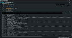
    You can check and test, in my case it seems to work fine. Operation from remote control and encoder works:

    Screenshot of Arduino IDE with code for ESP32. .

Topic summary

The discussion centers on the development of an internet radio and audio file player based on the ESP32-S3-WROOM-1 module, featuring a custom-designed prototype PCB with OLED display and user controls including rotary encoders and buttons. Key challenges addressed include pin spacing discrepancies in the ESP32-S3 module footprint, integration of Wi-Fi connectivity with dynamic station list updates, and handling of Polish character encoding on the OLED display. The project uses Arduino IDE (version 2.3.2) with ESP-IDF support and requires enabling PSRAM. Audio playback supports MP3, AAC, and FLAC streams, with the ESP32-audioI2S library recommended over the incompatible Audio library. Users reported issues with SPI MISO pin assignment causing bootloader conflicts, resolved by reassigning MISO to pin 35. The project incorporates WiFiManager for network configuration, EEPROM and SD card storage for saving last played station and settings, and includes plans for tone control via an external KA2107 equalizer and a CS8673 amplifier module. Problems with encoder input stability and memory limitations for Bluetooth A2DP on ESP32-S3 were noted. The community suggested alternatives like KaRadio and ESP32-MiniWebRadio projects. Debugging tips include serial terminal logs for HTTP errors and flash memory erasure to resolve boot loops. The project is open-source on GitHub, encouraging forks and modifications. Additional features under development include browser-based updates, directory navigation, and potential audio recording to SD card.
Summary generated by the language model.
ADVERTISEMENT