logo elektroda
logo elektroda
X
logo elektroda

Internet radio and audio file player on ESP32-S3

MAJSTER XXL 101376 1232
ADVERTISEMENT
Treść została przetłumaczona polish » english Zobacz oryginalną wersję tematu
  • #721 21455052
    hevet
    Level 16  
    >>21454979 Registering there is cool. I created an account there for yoradio. I also have the files but have not used them for yoradio as I have it built on VS1053b.
  • ADVERTISEMENT
  • #722 21455112
    CodeBoy
    Level 33  
    robgold wrote:
    I can see that as many people as many different needs and ideas. There is an option on the remote control to skip station by station. However, on the radio it is good how there is a list because in 99 stations moving with a step of +1 can be slightly tiring. We will probably leave it as it is. Only in my version for the housing of the finished tuner I will leave it in the option with priority "volume" because something feels that in a moment a small TPA from TI will fly there and make an amplifier and then the volume control is a priority ;)
    .

    I, as I will ultimately also be doing this in the wake of the Sony, am also keen to join :) to your version :) .
  • #724 21455132
    ArturAVS
    Moderator
    I have a question for the Author, what kind of strange encoders did you use? Normal ones have outputs A, B, and ground and possibly SW (button). The ones in the original schematic (from the title post) are quite different;


    Diagram of a rotary encoder with labels: CLK, DT, SW, VCC, GND.
    .
  • ADVERTISEMENT
  • #725 21455234
    Slawek K.
    Level 35  
    They are not strange just normal, commonly available and used.
    There are pull-up resistors added on the encoder board.

    Below is a diagram :


    Rotary encoder schematic with pull-up resistors. .

    Greetings
  • #726 21455237
    ArturAVS
    Moderator
    @Slawek K. I know how typical encoders work. Here is a confusing description of the connections.
  • ADVERTISEMENT
  • #728 21455256
    ArturAVS
    Moderator
    Clk, Dt, Sw and VCC and GND. This suggests that the encoder is fitted with some electronics, which is not the case. A typical encoder has markings;


    Encoder connection diagram with designations A, B, C, and buttons S1 and S2.
    .

    A, B, C, A and B channels and C common. S1 and S2 are the button.
  • #729 21455263
    miroskop
    Level 23  
    I used ordinary (bare) encoders due to the fact that the ones with the board don't have a screw fixing (at least I couldn't find one with a thread), making it difficult to mount on the faceplate. I put the 10k pull-up resistors on the PCB. An additional plus is that you don't need to pull VCC to the encoders, four wires are enough.
    PS. However, I have now found encoders with board and thread :( .
  • #730 21455271
    ArturAVS
    Moderator
    @miroscope You have dispelled my doubts.
  • #731 21455323
    robgold
    Level 20  
    @ArturAVS
    These are (unfortunately) the effects of the "Arduino generation". Someone didn't "grasp" that an encoder has outputs A,B and works in Gray code. So they contrived to call one output Data and the other Clock. This was followed by the creation of such blow-ups, ready-made libraries. The world of ready-made modules is full of such "flowers".

    @miroscope
    Be careful with these off-the-shelf PCBs. I have several such encoders and they are of such poor quality that they fall apart in my hands. And when you add a big knob they just mechanically have a lot of play. It's better to buy a good branded encoder from TME.

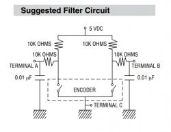
    Just as a curiosity, I will add the recommended filtration system by Bourns:
    Suggested filter circuit for a rotary encoder. .
  • #732 21455353
    ArturAVS
    Moderator
    @robgold Unfortunately, you may be right. However, at this point it's a bit disrespectful to the Author.... I asked because I already have all the components, and wanted to get myself up and running on a contactor for a trial run before I design a dedicated board (completely SMD).

    robgold wrote:
    I'd better buy a good branded encoder at TME.
    .
    It is from there that I have several in stock.
  • #733 21455402
    miroskop
    Level 23  
    I have already written about the use of these capacitors in the order of 10nF - 33nF several pages earlier. They have worked well for me.
  • #734 21455459
    robgold
    Level 20  
    Yes I remember, the capacitors seem obvious. I'm referring to that complete 10 Ohm, 10nF filter.
  • ADVERTISEMENT
  • #735 21455502
    miroskop
    Level 23  
    In the schematic it is 4x10kOhm. I didn't put these resistors in series, only the pull-up ones, but increased the capacitance to 33nF. You would have to check how the "full option" would work
  • #736 21455525
    Szaryczlowiek83
    Level 7  
    The missing components have just arrived and I'm getting on with the assembly this evening.
    Has anyone dealt with the JC2432s028N LCD display? It's a 2.8" display on a lil9341v library which has a miniSd card reader (I think because I can't find the specs for the devil) firstly I'm wondering if it will work, and secondly can anyone tell me how much the files on the card alone take up without the music.
    Electronic board with LCD display JC2432s028N and miniSD card slot.
    .
    LCD display JC2432s028N lying on a white background.
    .
    I'll post it if anyone is curious
  • #737 21455673
    robgold
    Level 20  
    >>21455502 Yes, k ate. I also have a 33nF because that's what I had on a quick version of the 0805 and it works. I think it's more about limiting contact current here. By doing a pull-up at the uP even 1k further the current will limit you by that 10k.
  • #738 21455781
    Slawek K.
    Level 35  
    robgold wrote:
    These are (unfortunately) the effects of the "Arduino generation". Someone didn't "grasp" that an encoder has outputs A,B and works in Gray code. So they contrived to call one output Data and the other Clock. This was followed by the creation of such blow-ups, ready-made libraries. The world of off-the-shelf modules is full of such "flowers".

    It begs the question, what does this change, it continues to be two encoder signals, no matter who calls them :) rather anyone who wants to build this radio must have some grasp of the basics of electronics, so they know how to connect such a simple component as an encoder.

    Greetings
  • #739 21455797
    ArturAVS
    Moderator
    @Slawek K. You know what, such a comment is an insult to my nearly 40 years of experience (I suspect not only mine). Elements and signals are described according to the datasheet, not according to your own personal opinion.
  • #740 21455817
    robgold
    Level 20  
    @Slawek K.
    I'll answer perversely...a couple of years ago there was a minister of education who wanted to change the MIL-STD description of digital gates into squares and rectangles in technical schools. Apparently you can...it's apparently the same thing but can you imagine analysing a circuit diagram in this way in a hurry ? However, description matters and here I agree with Arthur. Calling DT, CLK is simply misleading as if it were the output of a sliding register. This is not the fault of the author of the thread but simply the "Arduino" times we live in. On the one hand these modules simplified prototyping a lot and on the other hand they introduced a lot of bad things. We used to "piss" on Bascom and now we have Arduino. The language has changed, but the idea is the same.

    @ArturAVS
    You can say that Majster described correctly because you connect there ready-made modules with pulsers and pull-up resistors. And these modules have such designations. On the other hand, how the encoder itself was described by the author of the diagram of the Chinese module at his place, we will probably never know :) .

    The description of the modules themselves is faulty.

    @hevet
    ...and I downloaded these libraries ...and even uploaded....i.... how all these FLAC stations are suddenly working WITHOUT a FLAC...well that's a "mess" ;) because you will probably have to think about the SPDIF/Toslink output now ;) I knew that this configuration is a bottleneck because the author of the audio library writes about it but I didn't expect as much. It doesn't matter if the audio.loop dares us in a higher priority shuffle or in the main loop. It works in both cases. The limitation starts at stations transmitting 2500kbps

    By the way, I don't know why I can't fire up the config menu in my ESP-IDE. They throw me errors "-- Configuring incomplete, errors occurred!" Does anyone have experience on this what and how to do it in sequence ? I would like to have my compilation.
  • #741 21455863
    MAJSTER XXL
    Level 29  
    The encoders are printed on their small PCBs exactly as they appear in the wiring diagram, and why bother with combinations here. This is to give those interested in building a radio a simple and clear way to make connections between components.
    This is also how the ports are defined in the software.
  • #743 21455929
    Lechuuu
    Level 13  
    >>21454979 .
    @wirbud thanks for the information regarding the liblwip.a library swap - I had a problem with some stations e.g.
    Radio Spin (320kbps): https://s01.radiospin.pl/spin/

    because the buffer was empty almost all the time it liked to break from time to time.... now it buffers nicely and the port monitor does not scream that "##AUDIO.INFO#: slow stream, dropouts are possible". It worked with kernel 3.0.7.

    >>21455114 .
    @hevet thanks for the files - very useful. For now for YoRadio, but I'm already collecting the blocks and will be testing and forum radio at the weekend :) Hopefully by then I'll have the display covered - there are shortages on the market because you've bought them all out ;) .
  • #744 21455934
    hevet
    Level 16  
    I recompiled the radio with changed libraries, found a station in flac format which was interrupting, uploaded it and there is an improvement, the station plays without interruption.
  • #745 21456366
    wirbud
    Level 13  
    robgold wrote:
    @hevet
    ...and I downloaded these libraries ...and even uploaded....i.... how all these FLAC stations suddenly work WITHOUT any problems...well that's a "mess" because you will probably have to think about the SPDIF/Toslink output now I knew that this configuration is a bottleneck because the author of the audio library writes about it but I didn't expect as much. It doesn't matter if the audio.loop dares us in a higher priority shuffle or in the main loop. It works in both cases. The limitation starts at stations transmitting 2500kbps
    .

    But I'm glad I caused this problem with FLACs. It took 10 minutes to register with the russians ;-) Those handwritten bouquets - all the luck that you had to answer it with digits and not with cyrillic ;-) .

    Colleagues help - how to connect this yoradio with SSD1322 (ESP32S3 of course) On ESP32 and old libraries it goes. But with S3 it doesn't go - either a black screen or a mass of random dots. I kept the wiring diagram from the radio from this thread but the soft was supposed to be alternate - Yoradio - robgold....
    By the way - on Yoradio I extracted this MCLK for this cheaper Toslink/Spdiff board on WM8805. I think there are minor changes in 4 files.
  • #747 21456387
    robgold
    Level 20  
    @wirbud do you have parallel DAC and output to SPDIF or just SPDIF ?

    Very good of you to motivate us to act. I will play around and try to recompile it myself.

    In general, sometimes I have the impression that this radio is not about having a radio, but about having entertainment for winter days by writing software. Just having a radio is like a side effect ;) .
  • #748 21456390
    wirbud
    Level 13  
    >>21456381 I tried but this generator does not allow to select and define other SPI pins than the standard ones. And the whole plan goes to hell. I won't upload the version from the thread later. So now I'm thinking if maybe it's the clock frequency.... maybe I'll look here some more....

    Display of an electronic device with interference in the form of black and white stripes and pixels.
  • #749 21456395
    robgold
    Level 20  
    @wirbud

    Just as a quick note, see if it works SSD1322 to yoRadio in the myoptions.h file. I wrote this from "my finger" so no guarantees:

    Code: C / C++
    Log in, to see the code
    .

    Instead of #define TFT_SCK 45 it could be #define TFT_SCLK 45 but rather SCK.
    In the second attempt, still change HSPI to true.

    In this file at your place you have SPI definitions, swap to "our" leads and it should work.
    Link .
  • #750 21456403
    wirbud
    Level 13  
    >>21456395 I've done this before too.... just not sure - do you have to restart the Arduino after these changes and possibly wipe the ESP32S3? I haven't done that so maybe that's why there were no results?
    Thanks...

Topic summary

The discussion revolves around building an internet radio and audio file player using the ESP32-S3 microcontroller. The project includes features such as an OLED display, Wi-Fi connectivity, and audio playback capabilities. Users share their experiences with hardware setup, including issues with pin configurations, library compatibility, and troubleshooting compilation errors in the Arduino IDE. Suggestions for libraries, such as ESP32-audioI2S and WiFiManager, are provided to enhance functionality. Participants also discuss the importance of proper wiring, capacitor usage for encoders, and the potential for adding features like DLNA support and a web management interface for radio station management. Several users report on their progress, share code snippets, and offer solutions to common problems encountered during development.
Summary generated by the language model.
ADVERTISEMENT