logo elektroda
logo elektroda
X
logo elektroda

Internet radio and audio file player on ESP32-S3

MAJSTER XXL 126687 1329
ADVERTISEMENT
Treść została przetłumaczona polish » english Zobacz oryginalną wersję tematu
📢 Listen (AI):
  • #781 21458499
    DJCheester
    Level 26  
    Well that's what I thought just now and that's what I will do.

    And regarding the software without encoders, if you could say something about disabling them, what needs to be changed in the software or send me two files of the original robgold and yours with changes, I would compare.

    Thanks.
  • ADVERTISEMENT
  • #782 21458505
    hevet
    Level 16  
    A lot of things have to be changed, I even deleted too much, I found one bug related to the station list. I will redo the new version from robgold when I have time
  • #783 21458509
    DJCheester
    Level 26  
    Well I would appreciate such a final version as I am planning to make a PCB v2.0 with ir option and a slot for an encoder but the assumption is that it will not be mounted and an I2S lead for a converter for digital audio. But these are just plans for now I am enjoying and listening to PCB V1.0

    Greetings...
  • #784 21458513
    robgold
    Level 20  
    @hevet

    What is this error related to the station list you found ? Give it here, we will deal with it right away :) .
  • #785 21458518
    DJCheester
    Level 26  
    robgold wrote:
    By the way you can share the reworking of the Sony Tuner, front panel and printed adapters slowly nearing completion

    https://obrazki.elektroda.pl/8013687500_1740599849.png

    Just such an addition, I will upload the revised banks from tomorrow:
    Banks 15 - a lot of stations flew out (were dead) FLAC stations rewritten to Bank 16
    Bank 16 - it will be a high resolution bank, HQ or just with FLAC stations.


    Robgold I'm wondering if the metal casing on this Sonik will not screen the WiFi syghn for the ESP ?

    The block will be beautiful already 😀

    Greetings ...
  • ADVERTISEMENT
  • #786 21458560
    robgold
    Level 20  
    @DJCheester

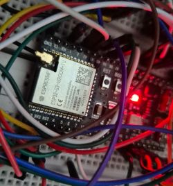
    The answer is simple. I swapped in one china PCB module for an ESP32 original with an antenna output and have a U.FL pass-through plugged into the SMA and there already an antenna from the old router.

    ESP32 module on a board with multiple colorful wires. .
  • #787 21458562
    DJCheester
    Level 26  
    Well, now you've reassured me 😀

    Added after 27 [minutes]:

    wirbud wrote:
    Not going - request with #define I2S_MCLK 16 declaration not transferred.
    It's 0 in the library - I'll solder it over and see if it plays.

    Robgold - how on one encoder do you change the bank? With two, the first one was pressed for 2 seconds and that was it. With one (2nd) it doesn't work.
    I don't have one in the remote either - maybe I programmed the buttons wrong.


    Hi did fellow wirbud manage to get the digital outputs working with this converter over I2S on this radio ?

    And if so, has your colleague connected both converters at the same time, i.e. our PCM and the one for digital audio, so as to have analogue and digital outputs ?

    If it would work I would design a PCB v.2.0 with a connector just for this module ?

    Greetings ...

    Greetings....
  • #788 21458674
    Szaryczlowiek83
    Level 7  
    Anyone had a problem switching the esp32-s3 Dec board to flasch? According to Ess. instructions. connect usb - press res - press boot - release res - after detection release boot. And nothing when I try to upload bin I get info that unrecognized chip and when I try IDE it hangs on compiling. No error, it just doesn't respond. On the other hand when trying to upload on esp32d0 or esp32s3 mini no problem. Any ideas?
  • #789 21458767
    hevet
    Level 16  
    robgold wrote:
    @hevet

    What is this error related to the station list you found ? Give it here, we'll deal with it right away :)


    Rest assured, in this truncated version of mine without encoders, I have removed too much :)
  • #790 21458815
    wirbud
    Level 13  
    DJCheester wrote:
    Hello, has my colleague wirbud managed to run digital outputs with this converter over I2S on this radio ?
    Also, has your colleague connected both converters at the same time, i.e. our PCM and the one for digital audio, so that you have analogue and digital outputs ?

    It runs just fine - after libraries with fixes, this FLAC plays without interruption (on most stations - because there are some that freeze the radio (robgold).
    MCLK can be in this radio on any leg - I've checked on 16 and 0. In yoradio for sure leg 0 is working. I think 16 didn't work for me - but I'll confirm, because I installed the newest MOD and there was something wrong with Polish language.
    It plays phenomenally - and I hooked up the WM8805 board together with the PCM5102A board and the TOSLINK was working and the headphone jack also played music. So there are 2 I2S receivers running in parallel.
  • #791 21458995
    robgold
    Level 20  
    You have to pay attention to what one colleague already mentioned when I was "struggling" with the player and FLAC files. The stations must be in 16bit, 44, 48kHz format. There are quite a few stations broadcasting FLAC 24bit and it will not work.

    @wirbud in theory the toslink i.e. optical SPDIF and PCM converter should go together because it only gets signals over i2s, it doesn't send anything. Thanks for confirming this with a "live" example.

    Added after 2 [hours] 24 [minutes]: .

    Quick update for Evo 3.15 Link

    - I made the mentioned screen dimming after 10 sec. Dimming does not work if you manually turn on the dimmer with the button on the remote control because then you have the lowest brightness level. What do we "turn" - >variable:

    Code: C / C++
    Log in, to see the code
    .

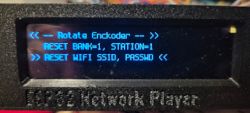
    - from now on there is a "RECOVERY" mode, what does this mean ? If, for some reason, the radio hits a station which resets it and you do not want to take out the card and manually edit the file with the station number and the bank number, hold down the encoder 2 during the restart. You enter the Recovery mode. In this mode you can:

    reset the settings to Bank=1, Station=1
    reset WiFi settings, the next time the radio will ask to connect to the wifi network "ESP Radio" and set a new SSID and Password to wifi.

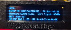
    In addition, under the rcCmdRed button you will also see the so-called BasicInfo about the radio. Providing basic parameters of the radio like serial number, firmware, network you are connected to, wifi signal strength, IP address, MAC number.

    ESP32 Network Player display with reset options. .
    Display of an ESP32 Network Player showing WiFi connection information. .
  • #792 21459240
    DJCheester
    Level 26  
    Well, the JST connector for the TOSLINK converter on PCB 2.0 is a must.

    wirbud can you upload a picture with the signal sequence on this module ?

    Buddy robgold, is it possible to add a declaration for this MCLK pin 16 and use the radio without a TOSLINK converter connected (for the time being), if so, this could be made permanent e.g. with the next update.

    Greetings ...
  • #794 21459249
    DJCheester
    Level 26  
    And the power supply of this 5V ? Pull up the 5V ?
  • ADVERTISEMENT
  • #795 21459255
    wirbud
    Level 13  
    >>21459249 5V needed. May not work on 3.3V
  • #796 21459256
    robgold
    Level 20  
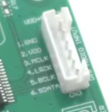
    Chinaman wrote:

    1 feet-----> GND
    2 feet----->VDD, for 5 V to 12 V DC power supply
    3-pin-----> MCLK master clock input
    4 feet----->LRCK clock input
    5-pin-----> Bit clock input BCLK
    6-foot-----> SDATA data input

    And yes by our way there is a 3.3V stabiliser on the PCB so 5V is required to make it work.
  • ADVERTISEMENT
  • #797 21459258
    DJCheester
    Level 26  
    Well 5v we have from USB so there is no problem, and on the module as there is a stabiliser it flies with 3.3v logic so everything can be directly connected.

    Greetings...
  • #798 21459289
    wirbud
    Level 13  
    By the way - WM8805 - if anyone would like to buy this from Ali - it's the transmitter version - the main difference is that it's not supposed to have a quartz generator on board - it's supposed to be blank there. With the quartz they make receivers.
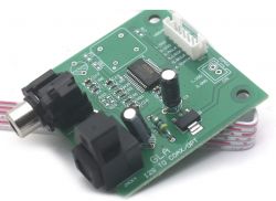
    GLA I2S to COAX/OPT circuit board with various electronic components and connectors. .

    Curiosity - in yoradio - SPDIF goes without a screen on legs 9,3,1,16 (Wolle set), but when I declare a screen in the code, I attach a screen - it goes screen and silence from digits....
    this is the code I have and I don't understand why something is jamming it....
    #define ARDUINO_ESP32S3_DEV

    #define L10N_LANGUAGE RU
    //=========================== TFT ================================================

    // without screen spdif works and with screen silence - probably conflict with SPI and 9th leg ....

    #define DSP_MODEL DSP_GC9A01A
    #define TFT_MOSI 11 //SDA or 35 (FSPI D )
    #//define TFT_SCLK 12 //SCL or 36 (FSPI CLK )
    #//define TFT_MISO 13 // or 37 (FSPI Q )
    #define BRIGHTNESS_PIN 255
    #define TFT_DC 40 // 9 // DC
    #define TFT_CS 42 // 10 // CS or 34 (FSPI CS0 )
    #define TFT_RST -1

    /================================== I2S DAC ===============================================
    #define I2S_DOUT 9 //16 // /* DOUT pin.
    #define I2S_BCLK 3 //17 /* BCLK bit clock */
    #define I2S_LRC 1 //18 /* WSEL Left Right Clock */
    #define I2S_MCLK 16
    #define VS1053_CS 255
  • #799 21459315
    efi222
    Level 20  
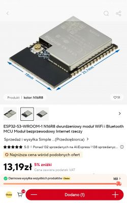
    As this radio develops I am gaining a desire to build it. Respect and thanks to its creators :) .
    So much so that I will rather opt for the "bare" modules. I even managed to find a module with PCB antenna and antenna socket.
    ESP32-S3-WROOM-1 N16R8 WiFi and Bluetooth module displayed with dimensions 25.7 mm by 18 mm. .
    I somehow have no confidence in goldpin connections in the long run.... And already with contact boards and ESP, it is some kind of misunderstanding.
  • #801 21460546
    wirbud
    Level 13  
    robgold wrote:
    You must pay attention to what one colleague already mentioned when I was "struggling" with the player and FLAC files. The stations must be in 16bit, 44, 48kHz format. There are quite a few stations broadcasting FLAC 24bit and it won't work.

    - and nato there's a solution in the library too - but I didn't explore because I haven't come across these stations. After all, the problem was simple FLAC from many stations.... You need to raise the sampling rate from 128 to 256 or even 512 .... if I'm not mistaken. This sits in Audio.cpp.

    ROBGOLD - where to find these stations with 24 bits. I would listen on the comp or is it worth the struggle? Thanks though for one or two.
  • #803 21460604
    wirbud
    Level 13  
    >>21460582 thanks - but great! I'm listening to the japanese right now ... there are two of us listening in the world.... about 3 ...someone joined ;-)
  • #804 21461423
    robgold
    Level 20  
    FLAC stations from https://www.hiresaudio.online that played correctly from today are in Bank 16 on GitHub. Get yourself a "Network Update". Enjoy listening.

    Build: .
    I fell into the hands of a very interesting enclosure of native manufacture "Maszczyk" KM-106 Link It even seems made for an application such as our radio. Wide, low, initial measurements seem to confirm that the 3.12 OLED display will go in without a problem plus you can give one or two encoders. Priced very reasonably too. As I have access to a physical panel I will probably design something under 3D printing for it.
  • #805 21461562
    CodeBoy
    Level 33  
    Nice case, as if you were doing the Front Panel I would smile at you (I don't have a 3D printer), of course we would settle :)
  • #806 21461637
    robgold
    Level 20  
    Welcome,

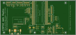
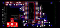
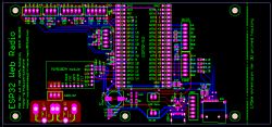
    On GitHub I uploaded preliminary gerbers for the basic PCB version of this radio -> HERE Link .
    The board is made as a kind of "breakout board" so that the radio can be put together using ready-made modules. I distributed the power supply, there is an option for 2x encoder, IR receiver, ADC or i2c keyboard, joystick, which is in the Majster version. I've also thrown in an SD card slot (here I still need to check the connections are correct). There is also a USB-C connector configured with CC pins to give 5V, plus ESD protection on it.

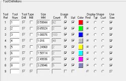
    I've had a preliminary look at the CAMs and ViewMate, everything seems OK, but you know I might have missed something, and since boards in China are cheap but not free, please take a look if there are any obvious errors before I send it to production. I know that the tools (drills) are not yet sorted out in these Gerbers but I will put this together before sending it off to production. Excellon in 1:4 format

    Gerbers can be viewed with many different programs like GerberLogix, ViewMate, CAM350 on the PCBWay website Link there is also a free viewer.


    PCB design for ESP32 Internet Radio .
    PCB schematic for ESP32 radio with marked modules and connectors. .
    PCB design for ESP32 radio .
    Tool definition table with various sizes and colors. .
  • #807 21461654
    DJCheester
    Level 26  
    Hi if I may interject and what I am missing in my previously etched PCB could a solder jumper be made preferably for the Vcc of the SD card to pull up 3.3V and 5V for the use of these largerSD card modules with a stabiliser on board.
    The card voltage selection would be done like the jumpers on the PCM module by soldering the pads side by side with a drop of tin.

    Other than that spicy mate robgold 😀.

    Greetings...
  • #808 21461660
    hevet
    Level 16  
    I am also in favour of this, I have card readers on 5V.
  • #809 21461678
    CodeBoy
    Level 33  
    @robgold but chad if you get a quote let me know, I would love to buy 2 pieces :) or at least 1 :)
  • #810 21461691
    Slawek K.
    Level 35  
    To make it a cheaper PCB in Chinese, you need to close below 100mm, there is so much free space here that you could easily fit this on the aforementioned format :) .

    Greetings
📢 Listen (AI):

Topic summary

The discussion centers on the development of an internet radio and audio file player based on the ESP32-S3-WROOM-1 module, featuring a custom-designed prototype PCB with OLED display and user controls including rotary encoders and buttons. Key challenges addressed include pin spacing discrepancies in the ESP32-S3 module footprint, integration of Wi-Fi connectivity with dynamic station list updates, and handling of Polish character encoding on the OLED display. The project uses Arduino IDE (version 2.3.2) with ESP-IDF support and requires enabling PSRAM. Audio playback supports MP3, AAC, and FLAC streams, with the ESP32-audioI2S library recommended over the incompatible Audio library. Users reported issues with SPI MISO pin assignment causing bootloader conflicts, resolved by reassigning MISO to pin 35. The project incorporates WiFiManager for network configuration, EEPROM and SD card storage for saving last played station and settings, and includes plans for tone control via an external KA2107 equalizer and a CS8673 amplifier module. Problems with encoder input stability and memory limitations for Bluetooth A2DP on ESP32-S3 were noted. The community suggested alternatives like KaRadio and ESP32-MiniWebRadio projects. Debugging tips include serial terminal logs for HTTP errors and flash memory erasure to resolve boot loops. The project is open-source on GitHub, encouraging forks and modifications. Additional features under development include browser-based updates, directory navigation, and potential audio recording to SD card.
Summary generated by the language model.
ADVERTISEMENT