logo elektroda
logo elektroda
X
logo elektroda

LCR-T4 electronics components tester ATMega328 - Test and Review

TechEkspert 228543 650
ADVERTISEMENT
Treść została przetłumaczona polish » english Zobacz oryginalną wersję tematu
Listen:
  • #451 16897189
    brofran
    Level 41  
    Posts: 6653
    Help: 650
    Rate: 1408
    pawelr98 wrote:
    I was preparing the second power amplifier on KD502.
    Someone mentioned earlier that this tester is not intended for high power transistors, that's why this type of elements should not be measured.
  • ADVERTISEMENT
  • #452 16897336
    pawelr98
    Level 39  
    Posts: 6464
    Help: 413
    Rate: 1155
    I wonder, however, why another copy of the same transistor was detected correctly. I still have several copies of KD502, I will see how the tester will detect them. With high power transistors I have 2N3055 / KD3055, TIP2955, BD911, BD912, KD502.
  • #453 16904442
    miszczo997
    Level 28  
    Posts: 1052
    Help: 134
    Rate: 159
    Where can I find the instructions for assembling the old tester enclosure, because I see now redirects to the post of the last year's gulson post regarding the new version?
  • ADVERTISEMENT
  • #455 16904711
    CMS
    VIP Meritorious for electroda.pl
    Posts: 8468
    Help: 258
    Rate: 2601
    miszczo997 wrote:
    Where can I find the instructions for assembling the old tester enclosure, because I see now redirects to the post of the last year's gulson post regarding the new version?
    People, what is with you? You really need instructions to assemble a cube from cut-to-size elements :shocked!:
  • #456 16904774
    sylweksylwina
    Moderator of Computers service
    Posts: 13217
    Help: 1882
    Rate: 2355
    Exactly, you can submit yourself without instructions.
  • #457 16904813
    miszczo997
    Level 28  
    Posts: 1052
    Help: 134
    Rate: 159
    That's exactly what the housing does not fit, because I probably have a new version of the tester, and the old housing and something did not suit me :P Well, you'll need to drill through additional holes. Edit: However, it has exceeded me and everything is ok :D It just looks like the hole spacing in the new version is about 3mm wider in the vertical and by applying the plate to the casing looked like the holes did not overlap.
  • ADVERTISEMENT
  • #458 16947579
    brofran
    Level 41  
    Posts: 6653
    Help: 650
    Rate: 1408
    I recently got a tester, so I will share my observations. 1- measurement of layered silicon diodes - OK, while old blade type eg DOG 58 signals as a capacitor, or unrecognized 2-transistors with a metal housing should be measured without touching them during measurement, because the results then different 3- top housing plate is matte and therefore the LCD is dimmed. Maybe someone will come up with a way to polish it "to shine". :D 4- the bottom of the housing is good to stick with 4 pieces of soft plastic, because the fixing screws can scratch the delicate table tops. Well, I gave "bodies", I did not read about the film. :D :D
  • #459 16947738
    Ricoh_220

    Level 38  
    Posts: 3714
    Help: 464
    Rate: 754
    And you peeled off the foil? That's not why it's dull. https://www.elektroda.pl/rtvforum/topic3354445-420.html#16887286
    Attachments:
    • LCR-T4 electronics components tester ATMega328 - Test and Review 20180109_141308[1].jpg (942.88 KB) You must be logged in to download this attachment.
    Company Account:
    Zakład techniki biurowej"Kserograf" .Serwis kserokopiarek i urzdzeń marki ricoh
    Bronowicka 73, Kraków, 30-091 | Tel.: 603XXXXXX (Show) | Company Website: https://kserograf.e.pl
  • #460 16947747
    Jawi_P
    Level 36  
    Posts: 3259
    Help: 260
    Rate: 715
    CMS wrote:
    People, what is with you? You really need instructions to assemble a cube from cut-to-size elements
    The claims to Minister Giertych have cut stereotypes in schools ;) I also do not understand the need for instructions, all in all it is necessary to appreciate the fun-puzzle and saving forests :)
  • #461 16947889
    gumisie
    Level 43  
    Posts: 17940
    Help: 1667
    Rate: 2486
    brofran wrote:
    3- the top housing plate is matte and therefore the LCD is dimmed. Maybe someone will come up with a way to polish it "to shine". :D
    Maybe it's enough to do what:
    Ricoh_220 wrote:
    And you peeled off the foil?
    brofran wrote:
    4- the bottom of the housing is good to stick with 4 pieces of soft plastic, because the fixing screws can scratch the delicate table tops.
    It can be solved in any way, it has already been described in this topic. greetings
  • #463 16948226
    nanab
    Level 27  
    Posts: 1092
    Help: 90
    Rate: 239
    Did someone power the tester at 1x18650? You can see that the housing and plate are designed dimensionally just under 1865, it comes in perfectly, but what changes in the system must be made to make it move? I put the + 5v link on the stabilizer, before I gave 5V + change in the divider (lower 10k resistor instead of 3.3k) so that it does not cry that the battery is discharged. Now he turns on, tries to test but he can not - what I would not put on it always shows me the 8mV link. On the power supply from the 9V power supply before the alterations I checked and recognized the resistors.
  • #464 16948430
    kkknc
    Level 43  
    Posts: 23771
    Help: 1916
    Rate: 6712
    The cheapest Ni-MH battery less than PLN 15 two for PLN 20 lithium from PLN 20, so is there any sense of fun?
  • #465 16948549
    nanab
    Level 27  
    Posts: 1092
    Help: 90
    Rate: 239
    The sense is that 18650 cost about PLN 0, because almost everyone has some of the waste. In the worst case, together with the inverter and housing, it's about 7 zlotys instead of 20. And also 4x more.
  • #466 16948566
    kkknc
    Level 43  
    Posts: 23771
    Help: 1916
    Rate: 6712
    You know, from waste, I would not count on having nominal capacity. And soldering, the use of cables, or even time would have to be counted.
  • #467 16948668
    miszczo997
    Level 28  
    Posts: 1052
    Help: 134
    Rate: 159
    I quickly gave the step up converter with MT3608, which I bought for about 2 zlotys. For this liion battery from some Nokia 1600, and for charging and protection against discharging the battery module on tp4056.
  • #468 16948693
    nanab
    Level 27  
    Posts: 1092
    Help: 90
    Rate: 239
    Even if they have less, it is still much more than a 9 volt battery. The cable is in the price of the tester, and soldering it maybe 1/100 hours times the 20 PLN / h is somehow 20 groszy work comes out. Besides, I would have to buy a 9 V battery (more time and money for fuel), and 18650 and converter I have at home.
    miszczo997 wrote:
    I quickly gave the step up inverter from MT3608, which I bought for about PLN 2. For this liion battery from some nok 1600, and for charging and protection against discharging the battery module on tp4056.
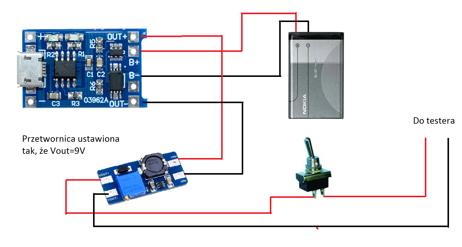
    Where did you connect, what kind of tension?
  • #469 16948742
    rafcio_21
    Level 29  
    Posts: 1110
    Help: 137
    Rate: 299
    You set the inverters to which 7-8V and plug in where the 9V battery was connected.
  • #470 16948747
    miszczo997
    Level 28  
    Posts: 1052
    Help: 134
    Rate: 159
    Tp4056 to the cell, the switch was just behind, because as I gave between the cell and the charging module, at the load with the converter itself, the protection did not give the output voltage. The total cost of items on aliexpress is about 3.5 PLN, in Poland probably 2x, but that's not much. LCR-T4 electronics components tester ATMega328 - Test and Review
  • ADVERTISEMENT
  • #471 16948749
    E8600
    Level 41  
    Posts: 8990
    Help: 529
    Rate: 2521
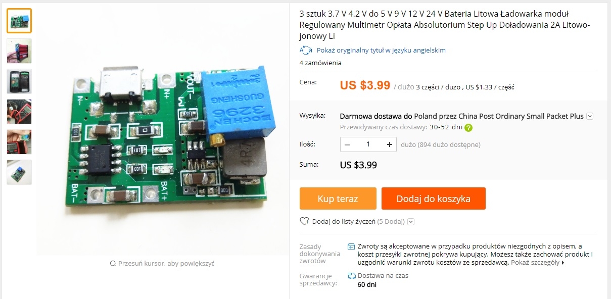
    For this application the best will be 2 in 1 or step-up adjustable inverter and charger in one (with protection against excessive Li-ion discharge). LCR-T4 electronics components tester ATMega328 - Test and Review
  • #472 16948869
    nanab
    Level 27  
    Posts: 1092
    Help: 90
    Rate: 239
    Is this 9V necessary to work? If it's not a bit of a sense to do around 9V first just to make them 5V. I already have small converters from power banks, but they are 5V rigid.
  • #473 16948922
    rafcio_21
    Level 29  
    Posts: 1110
    Help: 137
    Rate: 299
    Theoretically, you need 5V, but read about the modernization of this tester, I did not delve deeply, but it's about controlling the transistor that encloses the tester and there is some problem I preferred to give the 8 V for peace and calm rather than improve.
  • #474 16948940
    Jawi_P
    Level 36  
    Posts: 3259
    Help: 260
    Rate: 715
    E8600 wrote:
    For this application the best will be 2 in 1 or step-up adjustable inverter and charger in one (with protection against excessive Li-ion discharge).
    I admire you for the Internet :) A real man of the information society.
  • #475 16949112
    pawelr98
    Level 39  
    Posts: 6464
    Help: 413
    Rate: 1155
    kkknc wrote:
    You know, from waste, I would not count on having nominal capacity. And soldering, the use of cables, or even time would have to be counted.
    That's what they need to endure. The worst link I found was ~ 750mAh, best ~ 1350mAh at 1A discharge current. With smaller currents more will come. 14 cells from old laptops. I use these cells as an alternative to disposable links in portable devices (such as radio). I would just give 2x18650. As the voltage will stick, it will trigger a warning. The most economical option. At nominal 3.6V it will be 7.2V and for a full 4.2V it will be 8.4V. It fits nicely in the 9V battery voltage risk. And the capacity around 1000mAh should be enough.
  • #476 16949255
    Aress124
    Level 28  
    Posts: 1002
    Help: 152
    Rate: 214
    Can these testers measure resistances in two decimal places? How do you look on the Internet, in one picture they measure one decimal place and two places on which it depends? Measurement of such a low resistance with this tester is fairly reliable?
  • #477 16949288
    rafcio_21
    Level 29  
    Posts: 1110
    Help: 137
    Rate: 299
    Measurements depending on the downloaded software and the calibration performed are very similar to those of the multimeter and the measurement after the decimal point is more accurate at smaller resistances.
  • #478 16950352
    nanab
    Level 27  
    Posts: 1092
    Help: 90
    Rate: 239
    The 9V battery is about 150-200mAh, 18650 which I have about 1.5Ah recovered, and the new power bank bought for PLN 7.00 have 2Ah, so even the battery from the garbage or from the market for 5 PLN has 5x more capacity.
    pawelr98 wrote:
    I would just give 2x18650.
    Only the housing is designed for 1x18650, the two will not enter.
  • #479 16950575
    Jawi_P
    Level 36  
    Posts: 3259
    Help: 260
    Rate: 715
    It seems to me that the 6F22 battery is the optimal compromise. What do you replace such a battery with? I'm asking out of curiosity. Because I'm the Sunday "electronics" so I'm not a reference point. I would rather buy batteries for a dozen or so PLN than to combine with inverters.
  • #480 16950618
    rafcio_21
    Level 29  
    Posts: 1110
    Help: 137
    Rate: 299
    Jawi_P wrote:
    It seems to me that the 6F22 battery is the optimal compromise. What do you replace such a battery with? I'm asking out of curiosity. Because I'm the Sunday "electronics" so I'm not a reference point. I would rather buy batteries for a dozen or so PLN than to combine with inverters.
    It depends on how often you will use the tester, or maybe something like that will interest you.
    Attachments:
    • UNITEK-USB-6F22-9-V-akumulator-1200-mAh-litowo-jonowy-li-jonowy-kom-rek-na-mikrofon.jpg_50x50.jpg (1.78 KB) You must be logged in to download this attachment.
Listen:

Topic summary

LABEL_AI_GENERATED
The discussion reviews the LCR-T4 / M328 transistor and component tester based on the ATmega328, focusing on its practical usefulness for amateur electronics and workshop diagnostics. Users report that the tester automatically identifies discrete components and pinout, measures resistance, capacitance, inductance, diode forward voltage, transistor type and hFE, and can also test some thyristors and MOSFETs, though not always perfectly. The device is considered sufficiently accurate for hobby use, but several limitations are noted: poor inductance resolution, no reliable measurement below about 20 pF, sensitivity to battery voltage, occasional misidentification of semiconductors, and lack of protection against charged capacitors. Calibration by shorting all three test leads is emphasized, and some users install alternative firmware with more extensive calibration options. Mechanical issues dominate the review: the ZIF socket is fragile, the display ribbon and LCD can be damaged or pop out during shipping, and many recommend adding a protective enclosure or reinforcing the display. The thread also compares variants such as T4, T7, TC1, and color-display versions, and discusses availability, pricing, and sourcing from Elektroda shop, Allegro, eBay, AliExpress, and Banggood.
AI summary based on the discussion. May contain errors.

FAQ LABEL_AI_GENERATED

TL;DR: LCR-T4 auto-tests 14 part types, draws only 12-15 mA per measurement, and “will be useful in every workshop” [Elektroda, TechEkspert, post #16556695] Accuracy stays within ±2 % for most resistors. Firmware flashing adds live-scan mode and Zener tests. Why it matters: you get multimeter-level insight from a €10 gadget.

Quick Facts

• Supply: 9 V battery; 12-15 mA active, 20 nA sleep [Elektroda, 16556695] • R range: 0.1 Ω – 50 MΩ, C range: 25 pF – 100 000 µF, L range: 0.01 mH – 20 H [Elektroda, 16556695] • Typical accuracy: ±1 % R, ±3 % C, ±5 % L (user tests) [Elektroda, 16556695] • ESR read-out for electrolytics ≥1 µF [Elektroda, post #16556695] • Open-source firmware: AVR-based, 40 V boost for Zener mode [Elektroda, 16666684]
1. Which components does the LCR-T4 recognise?

It auto-detects resistors, capacitors, inductors, diodes (single & dual), LEDs, Zener diodes (≤30 V with updated firmware), BJTs, MOSFETs, JFETs, IGBTs (basic), thyristors, triacs, and voltage regulators [Elektroda, #16556695; #16666684].

2. How accurate are its measurements versus a quality multimeter?

User comparison showed 9.97 kΩ read as 10.18 kΩ (2 % high) and 100 µF read as 99.6 µF (0.4 % low) [Elektroda, 16556695] Inductance errors rise above 5 % near the 0.01 mH limit.

3. How do I calibrate the tester?

  1. Short pins 1-2-3 with low-resistance wire.
  2. Hold the single button until “Self-Test” appears.
  3. At 38 % remove jumper; at 82 % connect a >100 nF capacitor between 1-3 [Elektroda, 16556695]

4. What battery life can I expect?

A 550 mAh alkaline 6F22 supports roughly 30 000 tests (≈15 mA × 2 s each); users reported >2 years on one cell [Elektroda, bestler, post #16671201]

5. Why does my inductor show "resistor"?

The MCU flags coils below 0.01 mH or above 20 H as resistive. Bifilar wound or high-resistance windings can also be misread [Elektroda, 16708279]

6. Triac appears as NPN—faulty?

Not necessarily. High-gate-current triacs (e.g., KT207) may be detected as NPN when pin order flips. Confirm by testing both 180° rotations [Elektroda, 16585086]

7. What gains do I get from flashing new firmware?

Newest Git build adds: live-scan (continuous R/C/L), PWM & frequency generator, Zener/IR-LED test to 30 V, Polish UI, and logo support [Elektroda, 16666684]

8. How do I flash the AVR safely?

Use an ISP programmer, set fuses: LOW 0xE2, HIGH 0xD9, EXT 0xFC. Backup the factory hex first; then write the compiled .hex, verify, and power-cycle. Full guide in forum post #16666684.

9. Can I measure ESR in-circuit?

Yes for electrolytics ≥1 µF. Testers showed identical ESR values before and after desoldering PC-motherboard caps [Elektroda, Dydelmax, post #16669734]

10. What’s an edge-case the tester fails?

Charged capacitors can kill the input; one user cracked the LCD after a 50 V part was connected [Elektroda, 16579821] Always short large caps first.

11. How do I protect the ribbon display?

Stick 1 mm foam tape under the LCD and avoid flexing the gold ribbon. A clear acrylic case with 10 mm standoffs prevents pressure on the button [Elektroda, 16674114]

12. How do I assemble the acrylic enclosure?

Follow this 3-step: 1. Sandwich PCB between 10 mm spacers; 2. Insert LCD through front panel, secure with nuts; 3. Add rear plate and eight M3 screws [Elektroda, 16658664]

13. Why does the tester mis-show varicaps?

It measures junction capacitance at one bias only, so it logs them as ordinary diodes. A manual curve-tracer is needed for full C-V plots [Elektroda, 16689532]

14. Where can I buy or what’s the typical cost?

Ready-made LCR-T4 kits ship from AliExpress or eBay for €8–12; Polish stock adds ~40 % markup [Elektroda, 16567602] Shipping weight fits <2 cm letter rate.
AI summary based on the discussion. May contain errors.
ADVERTISEMENT