logo elektroda
logo elektroda
X
logo elektroda

[BK7231N ] Teardown and flashing of Tomzn TOMPD-63 WIFI (not to be confounded with TOMPD-63LW)

morgan_flint 16878 152
ADVERTISEMENT
  • #121 21363680
    mr_crabs
    Level 2  
    Hello folks! First of all thanks for the great piece of work you did!

    Inspired by your upgrade of this relay, I've started my teardown. First of all, I faced quite a different PCB with the Tuya CBU module instead of the one mentioned in this topic. The next thing that prevented me from proceeding was being unable to flash it in place, which seemed to happen because TuyaMCU interfered with UART. The "easiest" way was to desolder the wifi module and flash it. Thanks God and that LCD is made of "crystals" so my overheated areas perfectly cured themselves slowly 😅 

    Spoiler:
    Here is the PCB itself. Even the pinout for GND and 3.3V were shifted compared to one from the topic.
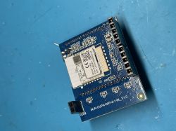
    Electronic module with a circuit board and Tuya CBU component. 


    The most recent problem was that I've been struggling to make things work properly with the latest autoexec.bat posted by AngelOfDeath which also is included in the OpenBeken repository. If I use this one, the main relay toggle goes off constantly. Just in a second after switching it on it goes off on the WebUI and also the same behavior with the physical button. Only the "original" autoexec.bat was working and some of the next revisions. Nothing interesting was mentioned in the logs so I had to perform manual debugging by commenting out the most needed features line by line.

    And as for now my learning is that placing "combined energy dpid" to the channel before the main relay one fixes the issue. What I mean by that is that combination DpID 16 -> channel 1, DpID 6 -> channel 2,3,4 wont work, while DpID 6 -> channel 1,2,3 DpID 16 -> channel 5 works fine.

    Here is the code that works fine on my device:

    
    clearIO
    SetFlag 46 1
    
    // start TuyaMCU driver
    startDriver TuyaMCU
    tuyaMcu_setBaudRate 9600
    
    waitFor MQTTState 1
    // tuyaMcu_defWiFiState 4
    
    // Breaker Id - Dpid 19 "breaker_id" -> channel 0
    linkTuyaMCUOutputToChannel 19 str 0
    setChannelType 0 ReadOnly
    setChannelLabel 0 "Breaker ID"
    
    // Measurements - Dpid 6 "phase_a" - channel RAW_TAC2121C_VCP -> channel(s) 1,2,3
    // TAC2121C VoltageCurrentPower Packet
    // This will automatically set voltage, power and current
    linkTuyaMCUOutputToChannel 6 RAW_TAC2121C_VCP
    setChannelType 1 Voltage_div10
    setChannelLabel 1 "Voltage"
    setChannelType 2 Power
    setChannelLabel 2 "Power"
    setChannelType 3 Current_div1000
    setChannelLabel 3 "Current"
    
    // Main Relay - Dpid 16 "switch" -> сhannel 4
    linkTuyaMCUOutputToChannel 16 bool 4
    setChannelType 4 toggle
    setChannelLabel 4 "Relay"
    
    // Prepayment on-off - Dpid 11 "switch_prepayment" -> channel 5
    linkTuyaMCUOutputToChannel 11 bool 5
    setChannelType 5 toggle
    setChannelLabel 5 "Prepayment"
    
    // Clear Energy Counters - Dpid 12 "clear_energy" -> channel 6
    linkTuyaMCUOutputToChannel 12 bool 6
    setChannelType 6 toggle
    setChannelLabel 6 "Clear Energy Counters"
    
    // Total energy - Dpid 1 "total_forward_energy" -> channel 7
    linkTuyaMCUOutputToChannel 1 val 7
    setChannelType 7 EnergyTotal_kWh_div100
    setChannelLabel 7 "Total Energy"
    
    // Leakage current - Dpid 15 "leakage_current" -> channel 8
    linkTuyaMCUOutputToChannel 15 val 8
    setChannelType 8 Current_div1000
    setChannelLabel 8 "Leakage Current"
    
    // Fault - Dpid 9 "fault" -> channel 9
    linkTuyaMCUOutputToChannel 9 raw 9
    setChannelType 9 ReadOnly
    setChannelLabel 9 "Fault"
    
    // Settings 2 - Dpid 18 "alarm_set_2" -> channel 10
    linkTuyaMCUOutputToChannel 18 raw 10
    setChannelType 10 ReadOnly
    setChannelLabel 10 "UV, OV, Max. Current Protections Settings"
    
    // Prepaid energy - Dpid 13 "balance_energy" -> channel 11
    linkTuyaMCUOutputToChannel 13 val 11
    setChannelType 11 EnergyTotal_kWh_div100
    setChannelLabel 11 "Total Prepaid Energy"
    
    // The above are read only channels. Except Settings 2 (mapped on channel 10), but since we cannot set it due to wrong parse of TuyaMCU driver - for now read only
    
    // Charge Prepayment - Dpid 14 "charge_energy" - channel 12
    linkTuyaMCUOutputToChannel 14 val 12
    setChannelType 12 TextField
    setChannelLabel 12 "Purchased Energy [kWh*100], i.e. 1kWh = 100"
    
    // Settings 1 - Dpid 17 "alarm_set_1" - channel 13
    linkTuyaMCUOutputToChannel 17 val 13
    setChannelType 13 TextField
    setChannelLabel 13 "Leakage Current Protection Settings"
    
    // Protection Reaction Time - Dpid 104 "over_vol_protect_time" (applied for all protections, regardless the name of DpID) -> channel 14
    linkTuyaMCUOutputToChannel 104 val 14
    setChannelType 14 TextField
    setChannelLabel 14 "Protection Reaction Time [s]"
    
    // Protection Recovery Time - Dpid 105 "over_vol_recovery_time" (applied for all protections, regardless the name of DpID) -> channel 15
    linkTuyaMCUOutputToChannel 105 val 15
    setChannelType 15 TextField
    setChannelLabel 15 "Protection Recovery Time [s]"
    
    tuyaMcu_sendQueryState


    Can anyone explain to me what's going on with that channels case?

    P.S. Right now, when I somehow have operational autoexec, I tried to upload alternative web UI but failed 🥲 I guess that the alternative web page is too big to be uploaded (POST request just fails) So I plan to rewrite the web page from scratch with some frontend best practices but keeping it close to the original. Will share with you if come up with anything good.
  • ADVERTISEMENT
  • #122 21363688
    p.kaczmarek2
    Moderator Smart Home
    RAW_TAC2121C_VCP has been recently updated and maybe I need to improve backwards compatibility, but the suggested usage is as in self test:
    Code: C / C++
    Log in, to see the code

    I will fix the default behaviour now, but the preferred usage is to specify the Voltage channel index and it will then assume that after voltage comes current and then power.
    Helpful post? Buy me a coffee.
  • ADVERTISEMENT
  • #123 21363758
    mr_crabs
    Level 2  
    >>21363688 Thank you for your fast response! It worked like a charm.
    I've created Pull Request with these modifications just in case, so feel free to close it if it isn't needed.
  • ADVERTISEMENT
  • #124 21363782
    p.kaczmarek2
    Moderator Smart Home
    Yesterday I fixed (tried to fix?) the old behaviour of VCP, which was not working before because I forget that channel was unsigned integer. Here is my fix:
    https://github.com/openshwprojects/OpenBK7231...mmit/f229e2c2047134b59e1e80c5e5ef3a05a214b62f
    Can you check whether the old VCP approach (without channel index in command) works now?
    Helpful post? Buy me a coffee.
  • #125 21367632
    morgan_flint
    Level 14  
    >>21363758 There's an error in your PR; because of the fixes made to RAW_TAC2121C_VCP, if you add the first channel number at the end of "linkTuyaMCUOutputToChannel 6 RAW_TAC2121C_VCP X", then you have to respect the order Voltage, Current, and Power (VCP) in the following channel type definitions:
    Comparison of two code versions with highlighted changes in parameter order.

    If you don't specify the first channel number after RAW_TAC2121C_VCP, then you can change (at least) the order of C and P, as in the original autoexec, and still get good results, so we have good backward compatibility. The first channel number is necessary for multi-phase meters but can be skipped in single-phase devices.

    More detailed info here and also in the previous posts
  • #126 21369339
    mr_crabs
    Level 2  
    >>21363782 Hi thank you! Updated firmware recently and checked - autoexec.bat without channel for VCP works as expected 👍

    PS. I'm still struggling with file uploads. Seems that device reboots when it receives a payload larger than 20000 or something. But will get back to it after I finish with mime types things. They seem not to be working as well 🥲
  • #127 21407056
    quantum8
    Level 2  
    After successfully flashing one of these devices, I ordered a second one but it appears they've changed the PCB layout again.

    This version has the wifi module mounted on the main board via a soldered in riser.

    I haven't attempted flashing it yet but will report back afterwards.
  • #128 21407060
    p.kaczmarek2
    Moderator Smart Home
    Make sure to take 2MB flash backup, it can help us with futher configuration.
    Helpful post? Buy me a coffee.
  • #129 21412055
    koshov
    Level 1  
    Hi everyone, I'm currently using 3 of these devices on each phase of my 3Ph+N grid supply as a means of protecting against abnormal voltage. I haven't yet torn down and re-flashed them, however I recently added them to Home Assistant using the Tuya Local integration and noticed that the power meter on the device reports much lower values than other metered relays.
    I have several DIN rail "Tongou" Tuya smart relays connected to single large loads that report values in line with what I'd expect for e.g. a heat pump, however the power usage on the 3 main phases reported by these Tomzn devices never exceeds ~100W and subsequently the metered values are a fraction of what I know is used "downstream" of them.
    It's worth mentioning that all loads on the 3 phases are connected to a common Earth/Neutral rail, thus I had to disable the leakage protection of the Tomzn - could that be the source of the issue?
    I wanted to check if folks here have similar experience and these devices just aren't suitable for metering before I go down the teardown and flashing rabbit hole. Cheers!
  • #130 21413748
    morgan_flint
    Level 14  
    koshov wrote:
    the power usage on the 3 main phases reported by these Tomzn devices never exceeds ~100W

    I've tested mine with ~2 kW and it reports power well
    koshov wrote:
    It's worth mentioning that all loads on the 3 phases are connected to a common Earth/Neutral rail, thus I had to disable the leakage protection of the Tomzn - could that be the source of the issue?

    Could you post the schematics for this, including how you connected the Tomzns?

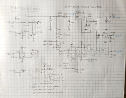
    EDIT: I've added this schematic to the first post:
    Circuit diagram of TOMPD-63 WiFi device

    As you can see, the current measurement shunt is inserted in the neutral, so how it's connected downstream of the device may affect the measurements. In my case, neutral is isolated from earth (at home, not at the utility's transformer), and each circuit downstream of the switchboard has independent phase and neutral wires so that I wouldn't have that problem
  • #131 21435942
    pexicele
    Level 2  
    Hi morgan_flint , acording to your schematic it seems that Tomzn can measure DC also, correct ? did you try it ? thank you.
  • #132 21436515
    morgan_flint
    Level 14  
    >>21435942
    I didn't try, but I don't think so, as the BL0942 is, in principle, an AC-only metering chip... It could be funny to see how it treats DC, but if, for example, it employs AC voltage zero crossing for something inside, it would have problems with DC.

    Apart from this, the DC/DC converter (PN8035Q) could work well from a certain DC voltage, if the positive is connected to the phase because of D2.

    Of course, leakage current wouldn't work, as it depends on a current transformer.
  • #134 21453780
    quantum8
    Level 2  
    A quick update on the board I have as I finally had a little time this evening;
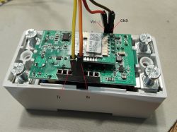
    It appears you don't need to solder anything to flash this device as all the pins are accessible via the headers now.

    Electronic board with cables connected to headers for Vcc, GND, Tx, and Rx.
  • #135 21487634
    leśny_ziutek
    Level 12  
    As the VoltageSet, CurrentSet, PowerSet commands doesn't work with this device (see >>21487463) is there any way to calibrate it? May ones require voltage calibration (3-4 V error).
  • #136 21487791
    morgan_flint
    Level 14  
    >>21487634
    Unfortunately, I don't think there's a simple way to calibrate it. As @p.kaczmarek2 says in the post you linked, in this case, the communication between the measuring IC (BL0942) is handled by the
    TuyaMCU, which serves the elaborated measurements info to the WiFi module, so any calibration should be done in the Tuya MCU's firmware, not accessible for us.

    In other similar TuyaMCU devices, I've seen calibration parameters in the settings menu and/or in the DPIds that could adjust for errors directly in the Tuya MCU but, apparently, that's not the case in this one, at least in the version installed in my device.

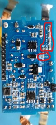
    If the error only affects voltage measurements, you could try a hardware approach by adjusting one of the resistors (R14-18 or R19) in the voltage divider connected to pin 4 of the BL0942, (see schematic at this post).

    Blue printed circuit board with various electronic components, including resistors marked in red.
  • ADVERTISEMENT
  • #137 21487906
    p.kaczmarek2
    Moderator Smart Home
    @leśny_ziutek maybe add here argument - delta?
    Screenshot of documentation related to TuyaMCU, showing a table with links and parameters.
    Helpful post? Buy me a coffee.
  • #138 21488607
    leśny_ziutek
    Level 12  
    @p.kaczmarek2 I didn't found anything about "delta" param. Is it an offset or a scale?

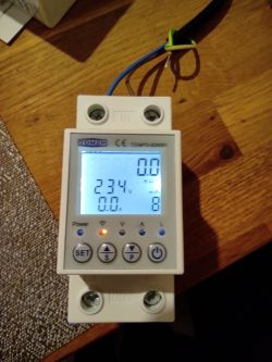
    @morgan_flint Mayby I'll try such hardware mod if anything on the software side doesn't help. So far I've managed to repair the filled down backlight connections on one of my units:

    TOMZN electronic energy meter on a wooden table.
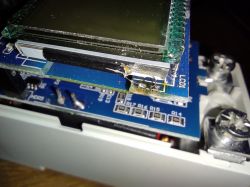
    Close-up of a printed circuit board with an attached LCD display.
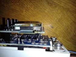
    Stack of circuit boards mounted against a wooden background.
  • #139 21488862
    p.kaczmarek2
    Moderator Smart Home
    leśny_ziutek wrote:
    @p.kaczmarek2 I didn't found anything about "delta" param. Is it an offset or a scale?

    It was an idea. A suggestion. I said that I can add something like that if you think that it would be useful.
    Helpful post? Buy me a coffee.
  • #140 21489087
    morgan_flint
    Level 14  
    Could something like a general "channel scale" or "channel math" function be useful for this and/or other applications? Starting with an offset + linear scale, for example...
  • #141 21491237
    p.kaczmarek2
    Moderator Smart Home
    @leśny_ziutek I added delta now.
    https://github.com/openshwprojects/OpenBK7231...mmit/b80fff5d409947ae9120712865df6af3fc469f28

    @morgan_flint there is already scale...
    
    linkTuyaMCUOutputToChannel [dpId] [varType] [channelID] [bDPCache] [mult] [inv] [delta]
    

    This is per dpID. Not for VCP yet.


    For VCP, we might use our WIP berry integration... but it depends on what do you need.

    Futhermore... well, @leśny_ziutek , we can only calibrate data sent to HA and shownin OBK. We can't calibrate data on screen, because it's sent directly from MCU to screen. OBK can't access that
    Helpful post? Buy me a coffee.
  • #142 21493013
    leśny_ziutek
    Level 12  
    p.kaczmarek2 wrote:
    We can't calibrate data on screen, because it's sent directly from MCU to screen. OBK can't access that

    Yes, I understand this. As a "software way" I was thinking about some way to send calibration data to the TuyaMCU (if it's possible at all and a way to do it will be discovered in the future). Apart from that a general linear scaler (multiplier and offset) can be useful on its own.
  • #143 21504906
    pexicele
    Level 2  
    Hi, I have Tompd 63 SW - wifi (color display) - flashed (OpenBK7231N_1.18.72) - i need an working autoexec.bat, I had tried many versions - none of them works ok, I even flashed my device with old firmware versions - no succes. I'm not able to update .html files - (it shows size 0 after upload.) There is something else updated since 1-2 years ago ? (i see posts with perfectly working devices..)
    Thanks for your help.

    LE : this seems to works ok :
    linkTuyaMCUOutputToChannel 6 RAW_TAC2121C_VCP
    setChannelType 5 Voltage_div10
    setChannelLabel 5 "Voltage"
    setChannelType 7 Current_div1000
    setChannelLabel 7 "Current"
    setChannelType 6 Power
    setChannelLabel 6 "Power"

    this not (return wrong value for current) :
    linkTuyaMCUOutputToChannel 6 RAW_TAC2121C_VCP
    setChannelType 5 Voltage_div10
    setChannelLabel 5 "Voltage"
    setChannelType 6 Power
    setChannelLabel 6 "Power"
    setChannelType 7 Current_div1000
    setChannelLabel 7 "Current"

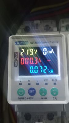
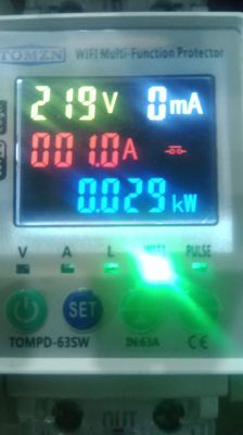
    and another thing: the device that "seems to work" has a non linear error for currrent (smaller current = bigger error) , I've attached pictures for a not-flashed and flashed devices.


    Display of TOMZN TOMP 63SW device with voltage, current, and power meters.
    Color display of the TOMPD 63SW device showing electrical measurements.

    Ok, sorry for spam, it seems that now there is not enough memory for autoexec + html file, don't know the reason. I was forced to slim down the autoexec file and remove comments and also the "Prepaid" part since I have no interest in this. Now is working.
  • #144 21507679
    rufus4
    Level 10  
    Would be nice if somebody could give me some information about the functionality/behavior of this product.

    Where I live the low voltage grid is all distributed in the air with power cables on posts. So we have a lot of interrupts and failures coming from the grid.
    Sometimes it happens that the power goes and comes on several times in a very short period. This creates dangerous voltage peaks killing electrical devices.
    (I'm connected with one phase only to the grid.)

    To prevent damages I installed a relay and a delay timer to wait 1-2 min. before connecting to the grid again after a failure. There is as well a voltage controler for over- and undervoltage.

    My question now is, does this power meter have a possibility to do the same delay after a power cut, or does it switch the relay straight away after power comes back on?
    And my second question, is the relay silent? I mean really silent and not noticeable if you stay in front of the power box where it's built in.

    thanks in advance!
  • #145 21508925
    morgan_flint
    Level 14  
    rufus4 wrote:
    My question now is, does this power meter have a possibility to do the same delay after a power cut, or does it switch the relay straight away after power comes back on?

    After a power cut, it remembers the previous state and, if it was "on", then it waits the time programmed in "restart time setting" (see pictures in the first post of this thread) before reconnecting. This time can be set from 1 to 500 seconds and is the same time it waits before reconnecting in case of actuation of any of the protections (over-under voltage, overcurrent, or leakage current)

    rufus4 wrote:
    And my second question, is the relay silent? I mean really silent and not noticeable if you stay in front of the power box where it's built in.

    No, it's not silent; there's an audible "click" when it changes state.

    You can see how it waits for the restart time and hear the sound in the attached video (the first "click" is from another device; the one from this device sounds when the countdown reaches 0):


  • #146 21509049
    rufus4
    Level 10  
    >>21508925 Thanks a lot for your helpful informations, thats very kind.

    About silent, I was thinking that maybe the relay makes noises when its armed like a electric contactor. Actually this is the biggest negative point of this product. It cuts L only and it uses a relay instead of a contactor.

    Anyway, all in all it still can be useful and it is very cheap.

    Maybe I could use it in combination with a quality contactor. Then it should be save.
  • #147 21510427
    morgan_flint
    Level 14  
    rufus4 wrote:
    ctually this is the biggest negative point of this product. It cuts L only and it uses a relay instead of a contactor.

    If you're concerned about this, there's a similar device which cuts both:
    https://www.elektroda.com/rtvforum/topic3995777.html
    You can see the two relays in the photos here and here
    By the way, these relays are bistable, so the coil is not fed continuously to keep them connected.
    I don't think a contactor would be less noisy than them.
  • #148 21510587
    rufus4
    Level 10  
    morgan_flint wrote:
    By the way, these relays are bistable, so the coil is not fed continuously to keep them connected.

    Okay, good to know. This is the answer about noise, there is none. Thanks again!

    About the contactor, usually you use these for bigger and possibly high inductive loads. I do not have so much confidence in this chinese branded relay. I'm afraid it will overheat because of worn-out contacts one day.

    Probably I do have to get one of these relays and take it appart into peaces for a visual check. And a "powerful sparky" short with 400V will show if the contacts are good. As an example: cheap quality circuit breakers (even european brands) can't stand this and contacts burn off, good ones do survive this torture sovereign.

    Added after 12 [minutes]:

    Oh, an other quiet important thing I realised now. If these relays are bestable. How can it happen that the relay is off after a power cut? Because then in practise it would be needed to first switch off after power returns.
    Is it guaranteed bestable?
  • #149 21510731
    morgan_flint
    Level 14  
    rufus4 wrote:
    I do have to get one of these relays and take it appart into peaces for a visual check

    I've already done that some time ago 😉

    As the relay I took apart was from another device (but similar to this one's), I've just posted the photos on that device's thread.

    Also, in the first post of that thread, you can find the Chinese datasheet of the relay driver IC. I didn't draw the schematic for that device, but the relay driver part must be very similar to this device's. You can see the schematic of this one here


    rufus4 wrote:
    Oh, an other quiet important thing I realised now. If these relays are bestable. How can it happen that the relay is off after a power cut?

    Good question!
    I don't know how it really does it (could be the Tuya MCU's firmware or a feature of the driver IC...) but, after disconnecting it from AC input, during the brief moment the display is still on (due to the internal power supply's electrolytic capacitor) you can hear the "click" of the relay switching off.

    EDIT: Maybe "latching relay" or "magnetic latching relay" is the correct name for this type... Here's a YouTube video showing one that looks much like the one on these devices (except for the 3-terminal coil; in our case, the driver IC inverts the polarity)

    Also, adding video where you can hear it disconnecting at the beginning. Also, I can check with a lamp connected to the output that it doesn't turn on after reconnecting the input to the device:


  • #150 21510782
    rufus4
    Level 10  
    morgan_flint wrote:
    Good question!
    I don't know how it really does it (could be the Tuya MCU's firmware or a feature of the driver IC...) but, after disconnecting it from AC input, during the brief moment the display is still on (due to the internal power supply's electrolytic capacitor) you can hear the "click" of the relay switching off

    Okay, so it must be done by a solution that when "power-off" a condensator is discharging through the coil of the relay and triggers it (or similar?!).

    morgan_flint wrote:
    As the relay I took apart was from another device (but similar to this one's), I've just posted the photos on that device's thread.

    nice... <thumbs-up>
    More and more I do realise that this is a energymeter-wifi-switch-toy and nothing else. It has absolutely nothing to do with safety. And it definitely pretends this with the leakage-ammometer, overvoltage and under/overcurrent functions. I don't think this is certified to be used in any legal electrical installation.

    Actually I would be aware of this product being used seriously. (On your picture of the relay, the shunt-resistant is positioned directly on the case of the relay, and so on....)
    At least my consent is to leave the fingers from that toy. Life is too valuable.

    Thanks again for all these helpful informations!

Topic summary

The discussion revolves around the teardown and flashing of the Tomzn TOMPD-63 WIFI device, focusing on its differences from similar models like TOMPD-63LW. Users share insights on the device's DpIDs, firmware issues, and the functionality of various settings, including alarm configurations and leakage current monitoring. The conversation highlights the challenges faced with TuyaMCU communication, particularly in parsing raw data and setting parameters through the OpenBeken firmware. Participants also discuss the implementation of a custom web interface for device control, troubleshooting methods, and the integration of the device with home automation systems. The need for improved documentation and user manuals is emphasized, along with suggestions for enhancing the device's features and usability.
Summary generated by the language model.
ADVERTISEMENT