logo elektroda
logo elektroda
X
logo elektroda

Internet radio and audio file player on ESP32-S3

MAJSTER XXL 114222 1263
ADVERTISEMENT
Treść została przetłumaczona polish » english Zobacz oryginalną wersję tematu
📢 Listen (AI):
  • #901 21474376
    MAJSTER XXL
    Level 29  
    With this time shifted forward by an hour, it was also like this last year as I remember correctly. It seems that the server has already set itself to daylight saving time and now you have to wait until the actual change or change the offset by hand.
    According to the query:
    Code: C / C++
    Log in, to see the code
    .

    a one is returned, i.e. that CEST daylight saving time is in effect.

    Code: C / C++
    Log in, to see the code
    .

    But this is kind of silly. The JSON data for my city from the weatherman also shows an hour ahead:
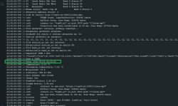
    Screenshot showing JSON results with date and time. .
  • ADVERTISEMENT
  • #902 21474580
    robgold
    Level 20  
    It appears as if the DST flag is set according to the US system. To be precise, from 10.03.2025, DST time applies in the US. The NTP server itself should keep UTC time.

    No surprise there. We do not set the timezone anywhere. A shift of 1h with respect to US time will produce exactly the error we have. You need to add a time zone and set it. I'll check, add and upload the fix to GitHub.

    Replacing the configTime line with the following solves the issue.

    Code: C / C++
    Log in, to see the code
    .

    Daylight saving time starts:
    M3 - third month of the year - March
    5 - last ...
    0 - Sunday of the month
    /2 at 2 a.m.

    Daylight saving time ends:
    M10 - in October
    5 - last ...
    0 - Sunday of the month
    /3 at 3 a.m.
  • #904 21475465
    DJCheester
    Level 26  
    rysin wrote:
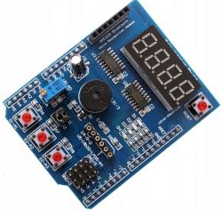
    @DJCheester Here you have the display for it. You don't need to combine anything.

    Multifunctional board with display for Arduino with buttons and module. .
    https://allegrolokalnie.pl/oferta/wielofunkcy...ietlaczem-arduino-uno-mega-byr?rep=1081205284


    But what does that get me, I am all about designing a PCB with the components of our ESP32 radio I showed earlier and on the overlay there will be a pcm sd amp Chinch and a socket for an OLED such would be an experimental radio.

    The PCB would then be made to coincide with the esp32 and using goldpins connect to the ESP uno board.

    Regards...
  • #905 21475559
    MAJSTER XXL
    Level 29  
    And I already thought I'd find a ready-made Sonatino dev board to buy somewhere, even @gulson made a mention here:
    https://www.elektroda.pl/rtvforum/topic4063796.html

    has everything you need on board:
    https://sonatino.com/

    just need to add the peripherals, and maybe @DJCheester can you advise opening the project?
    https://github.com/luminationlabs/Sonatino
  • #906 21475806
    DJCheester
    Level 26  
    I need to familiarise myself with what's on this github, but SMD soldering is not my fable, not these years and eyesight, as something to gerber do as there are files and to chine but I won't solder it myself anyway.

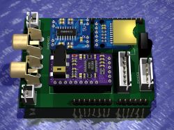
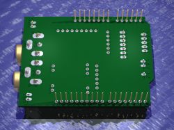
    I was thinking more of an overlay for this ESP32-Uno something like this

    Electronic module with various components, including audio connectors and encoders. .
    View of a printed circuit board with various connectors and pins designed as a shield for ESP32-Uno. .

    Audio speaker out, encoder and oled connectors
    audio chinch out sockets

    All applied to ESP32-Uno pins

    Greetings ...
  • ADVERTISEMENT
  • #907 21476073
    robgold
    Level 20  
    @MAJSTER XXL I also came across this Sonatino project. Quite tightly packed with everything. The project opens normally in KiCad. I'm not proficient in that environment because I've never drawn anything there but program like program. There's a lot of unnecessary stuff in Sonatino itself for a radio. There's a microphone preamp, a headphone amp. There is also another DAC (WM8524).
    PCB only to be manufactured in China because it is a 4-layer. Price unrealistic in PL.

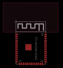
    If someone wants, I have created a library for ESP32-WROOM-1(U) for Eagle. Bede will draw his version of the module. Most likely in format as a "sandwich" under the OLED of this 3.12 inch.

    A snapshot from KiCad for the Sonatino:
    View of the Sonatino PCB design in KiCad software. .

    ESP32 component for Eagel:
    ESP32-WROOM-1(U) component in Eagle software with highlighted pins.
  • #908 21476633
    aangelo0971
    Level 1  
    Ciao a tutti, quale OLED display 2.42" 128x64px mi potreste dare link amazon ho aliexpress. c'e ne sono tanti. quale usi tu? Grazie mille
  • #909 21476792
    rysin
    Level 12  
    @DJCheester The Chinese will solder you if you send them a boom file.

    Added after 27 [minutes]:

    I have an ESP32 on a UNO-like board and it works well, but I don't see the point with an ESP32S3. Unless you make all the interfaces for the internet radio on it and output the UNO connectors standard like on this board what you showed. Like if you made the output under LAN then I might be tempted to get a ready-made one.

    Added after 13 [minutes]: .

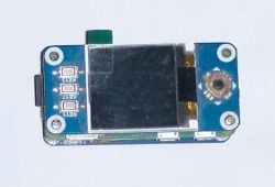
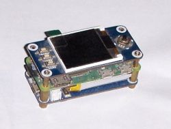
    As if anyone would like to make this SONATINO their own way, make it to the RPI zero standard. There are ready-made modules for this with displays including keypads and buttons as well as UPS batteries.


    Electronic module with display and buttons. .


    Small electronic module consisting of a display and PCB, assembled in layers. .
  • #910 21477053
    slaslo
    Level 17  
    @robgold tell me which version of your code supports mp3 playback from a memory card.
    Thank you.
  • #911 21477489
    robgold
    Level 20  
    @slaslo theoretically any because I didn't remove the player code, practically its code hasn't been updated for many revisions, it doesn't have many features that Majster added later. There is no alphabetical sorting for example. Generally doing the evolutions of "evo" I focused on the radio. I will most likely remove the mp3 player code altogether.
  • #912 21477694
    slaslo
    Level 17  
    @robgold thank you for the information. I have version 3.15 installed, the circuit built with two encoders and control from the remote control, the radio works perfectly (control, switching between banks etc). From the remote control I cannot switch to the player
    (#define rcCmdSrc 0x040B // Switching source radio, player) in my case it switches the view to a large clock with calendar.
    When switching to MUSIC PLAYER from the encoder it starts to play a file from the /music folder, but the remote unfortunately stops working, and the encoders can't be used to switch between songs / folders. Sometimes it hangs or restarts.

    Any suggestions in determining the cause of the problem welcome, thank you.
  • ADVERTISEMENT
  • #913 21477751
    robgold
    Level 20  
    The remote control does not support the player in evo at all. It will not work completely. The Source button is fastened just for switching on the clock ;) .
  • #914 21477798
    gabar5
    Level 12  
    Great job, I struggled a bit with uploading the software (I work on macOS), the system blocks communication with Chinese esp32 boards, it treats them as fakes. You need to install the virtual port drivers
    https://www.wch.cn/downloads/CH34XSER_MAC_ZIP.html
    and then click according to the instructions:
    https://community.platformio.org/t/fails-to-upload-to-esp32s3-wroom-1/38152/29

    If I only want to use the radio, I understand that I can skip the second encoder?
  • #915 21477822
    robgold
    Level 20  
    Yes, but it would be a good idea to block it or preferably remove it altogether because ESP will throw a declaration error for GPIO 255 in debug. This happens when you assign a value-1 to a port.
  • #916 21477841
    gabar5
    Level 12  
    It will be sufficient if I comment out commands containing
    CLK_PIN1
    DT_PIN1
    SW_PIN1
    ?
  • #917 21477865
    DJCheester
    Level 26  
    Welcome

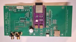
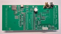
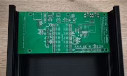
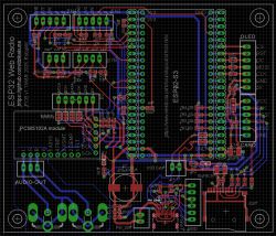
    Below I am attaching a new version of my first PCB - eagle file.

    The old version is available here

    https://www.elektroda.pl/rtvforum/topic4041603-540.html#21434558


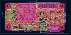
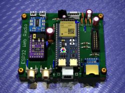
    Single-sided ESP32 Web Radio PCB with PAM8403 amplifier and electronic components. .
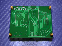
    Single-sided PCB with green laminate and yellow mounts. .
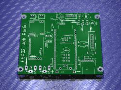
    Green PCB for ESP32 Web Radio project with labeled solder points and components. .
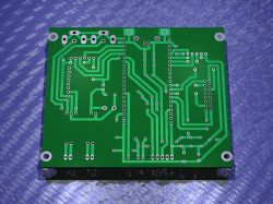
    Single-sided PCB with visible traces and mounting holes. .

    This is a "slimmed down" version - under Robgold's colleague's soft, single-sided easy to make using the home method - thermo-transfer.

    I resigned in it from a socket for colleague Major's joystick and connector for the first encoder (used for MP3 player in colleague Major's software).

    The board is less than 10x10cm in size - it contains a PAM8403 power amplifier. The jumper is used to power the amplifier.

    As for the software declaration I use without encoders - the radio works stably on such a declaration

    Code: Arduino
    Log in, to see the code
    .

    Switch is only assigned to the pin and the other two signals are declared to -1

    You can of course add 4.7-10k pull-up resistors under the CLK, DT, SW pins to 3.3V and this should also take care of the matter.

    Both the first and the second version of my PCB do not contain such resistors.

    Regards ...
  • #918 21478074
    DJCheester
    Level 26  
    rysin wrote:
    I have an ESP32 on a UNO-like board and it works well, but I don't see the point with an ESP32S3. Unless you make all the interfaces for the internet radio on it and output the UNO connectors standard like on this board what you showed. Like if you made an output under LAN then I might be tempted to get a ready-made one.


    I will order this version of the ESP32-S3-Uno as soon as I physically have it in my paws, then I will add the missing pins (sockets) and dimension it.

    Then I'll add what I need, because the render I gave regarding the overlay is just for now.

    Regards...
  • #919 21478445
    robgold
    Level 20  
    While we are on the subject of PCBs.... they have arrived !!! :) Exactly a week ago they left the factory. Now a bit of spare time and it will have to be assembled. The most important thing is that all key components like usb-c, card reader and RCA connectors fit perfectly. PCB adapted, of course, to the printed case as well as the Hamond.

    The factory also handled the slotted pads without a problem. This is not obvious, because Eagle in older versions did not have support for pads of this type natively. You have to draw the missing holes on the milling layer accordingly.

    PCB is supposedly a prototype but something feels that if everything works it will stay for longer ;) .

    PCB with ESP32 module and USB-C connectors along with a card reader.
    Green PCB with electronic components, including USB-C port, card reader, and RCA connectors. .
    Green PCB with visible traces and component slots, placed on a wooden surface. .

    PS If someone would like I have redesigned based on the same PCB schematic as a 100x85mm module with the Joystick connector omitted. This makes it possible to have 5pcs PCBs within 50PLN. (Up to the dimension of 100x100 PCBs in China are quite cheap, then unfortunately the price starts to increase)

    PCB design with components and traces. .
  • #920 21478453
    rysin
    Level 12  
    @DJCheester I was thinking of doing it together on the same board as the ESP32S3. Design the board for the chips and the Chinese will solder.
  • #921 21478488
    DJCheester
    Level 26  
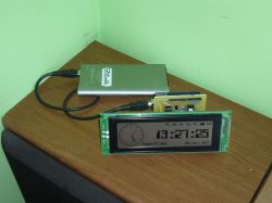
    Well I misunderstood a bit, I do this kind of overlays on the Arduino for specific projects and the idea that the "removable" Arduino is very practical. I want to do the same with this ESP32S3 Uno.

    Here an example of a clock on a graphic display and PCB as an overlay on an Arduino Uno

    LCD display with a clock connected to a powerbank on a table. .

    Now something similar I want to make a compilation like this only incorporating a radio and 7-pin lead and to this a large 5 inch OLED.

    Here in the picture is a 5 inch LCD just for comparison.

    Fellow Robgold dutifully please send the lbr for these Chinch sockets since the holes fit because in my case they are too small.
    You can also send the brd from this small version of your board then I will make a render tomorrow 😀 .
    It will be better to see.

    Greetings....
  • #922 21478624
    Slawek K.
    Level 35  
    Just remember that this version a'la Uno has fewer gpio pins than the regular one - so you don't miss ;) .

    Greetings
  • #923 21478652
    DJCheester
    Level 26  
    There should be enough pins

    https://pl.aliexpress.com/item/1005008143867026.html

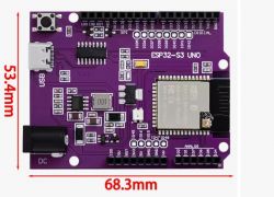
    The ones that aren't led out are on the pads I will make goldpin sockets and pins in my board so that they are all led out on my PCB.

    Purple ESP32-S3 UNO board with dimensions 53.4 mm by 68.3 mm .

    Unless some from the ESP module are not connected at all ?

    Greetings ...
  • ADVERTISEMENT
  • #924 21478730
    rysin
    Level 12  
    @DJCheester The board with the display and other panel elements as much as possible on the overlay, but the rest could be together. What are you going to power it with? If from 5 V then the whole power supply part is redundant, an LDO stabilizer such as LDL1117 with low voltage drop is enough. In that case you are left with only the ESP32S3 module on the board, which costs less than £20, not over £50 for the whole UNO.

    Added after 1 [hour] 28 [minutes]: .

    TechEkspert wrote:
    Maybe it would be possible to do a version of the project with ethernet connectivity?
    .

    If he thought well you could derive a USB generative instead of this for programming via UART. If he programmed it well, a network card could be connected to this USB and transmission would go over the cable, and there would be silence in the ether. It can be programmed with an external programmer or even via WIFI.
  • #925 21478891
    DJCheester
    Level 26  
    The power supply will be provided by the ESP32-Uno, there is a 5V inverter and a 3.3V stabiliser, nothing from the power supply will be on the frontend.
    On the frontend there will be only the modules I showed on the render, there will be discrete elements, resistors, capacitors, the encoder and the OLED display will be connected to the JST connectors.
    The whole ESPuno costs just over 20zl on Ali, so the costs are small. Besides, SMD soldering is not my cup of tea, so I will focus on ready-made modules plugged into the board, as I did in the two already available versions of the PCB with the ESP32-S3 44pin module.

    This is an idea for now, so we will see how it goes with time and ultimately during the creation of the next PCB when the ESPuno arrives

    Greetings ...
  • #927 21479084
    gabar5
    Level 12  
    Hi,
    I got stuck after connecting the PCM5102. It went off - silence
    Module connected correctly to ESP
    #define I2S_DOUT 13 // Connection to DIN pin on DAC
    #define I2S_BCLK 12 // Connection to BCK pin on DAC
    #define I2S_LRC 14 // Connection to LCK pin on DAC
    5V power supply, I tried with SCK to GND, connected jumpers H1L-H2L-H3L-H4L in different configurations, but no effect.

    I've also noticed that those bars under the radio subtitles don't appear
    Screen displaying information about a playing song and missing visualizer bars. .
  • #928 21479094
    ArturAVS
    Moderator
    gabar5 wrote:
    I've also noticed that those bars under the radio subtitles don't appear
    .
    These are 'drive out' indicators, if nothing is being played then what are they supposed to show?
  • #929 21479099
    gabar5
    Level 12  
    The serial port monitor shows
    i2s_common: i2s_channel_write(1211): The channel is not enabled

    any clues?
  • #930 21479209
    hevet
    Level 16  
    Check the correctness of the connections. Is there an LED on the PCM5102 module?
📢 Listen (AI):

Topic summary

The discussion centers on the development of an internet radio and audio file player based on the ESP32-S3-WROOM-1 module, featuring a custom-designed prototype PCB with OLED display and user controls including rotary encoders and buttons. Key challenges addressed include pin spacing discrepancies in the ESP32-S3 module footprint, integration of Wi-Fi connectivity with dynamic station list updates, and handling of Polish character encoding on the OLED display. The project uses Arduino IDE (version 2.3.2) with ESP-IDF support and requires enabling PSRAM. Audio playback supports MP3, AAC, and FLAC streams, with the ESP32-audioI2S library recommended over the incompatible Audio library. Users reported issues with SPI MISO pin assignment causing bootloader conflicts, resolved by reassigning MISO to pin 35. The project incorporates WiFiManager for network configuration, EEPROM and SD card storage for saving last played station and settings, and includes plans for tone control via an external KA2107 equalizer and a CS8673 amplifier module. Problems with encoder input stability and memory limitations for Bluetooth A2DP on ESP32-S3 were noted. The community suggested alternatives like KaRadio and ESP32-MiniWebRadio projects. Debugging tips include serial terminal logs for HTTP errors and flash memory erasure to resolve boot loops. The project is open-source on GitHub, encouraging forks and modifications. Additional features under development include browser-based updates, directory navigation, and potential audio recording to SD card.
Summary generated by the language model.
ADVERTISEMENT