logo elektroda
logo elektroda
X
logo elektroda

Internet radio and audio file player on ESP32-S3

MAJSTER XXL 101520 1232
ADVERTISEMENT
Treść została przetłumaczona polish » english Zobacz oryginalną wersję tematu
  • #931 21479226
    gabar5
    Level 12  
    Yes the diode lights up red, I checked the connections
    13pin esp - DIN
    12pin esp - BCK
    14pin esp - LCK
  • ADVERTISEMENT
  • #932 21479230
    hevet
    Level 16  
    And are the connecting cables Chinese or did you make them yourself? If you have the possibility, check with a meter if the connections are correct. Take a picture of how your jumpers are soldered.
  • #933 21479240
    gabar5
    Level 12  
    I made the cables myself, permanently soldered in the PCM and ESP
    I had the jumpers soldered like this
    Image of a PCB fragment with soldered components and a connection diagram. .
    I connected the SCK jumper, disconnected it, gave SCK to GND, tried it, but no effect.
  • #934 21479252
    hevet
    Level 16  
    I have the jumpers the same way. what version of Esp32 core are you using?
  • ADVERTISEMENT
  • #936 21479277
    hevet
    Level 16  
    I don't mean the board version but the esp32 boards version

    Screenshot of the board manager showing esp32 version 3.0.5 installed. .
  • #937 21479291
    gabar5
    Level 12  
    I'll check as at the computer, but I uploaded the latest version 4 days ago.
  • #938 21479297
    Slawek K.
    Level 35  
    The SCK from the PCM5102 doesn't matter if it is connected to GND or not, it has to work.
  • #939 21479302
    hevet
    Level 16  
    gabar5 wrote:
    I'll check as with the computer, but I uploaded the latest version 4 days ago.
    .
    Upload 3.0.7.
  • #940 21479303
    DJCheester
    Level 26  
    Maybe you have a trafficked PCM module, faulty modules happen, it would be good to connect another PCM module.

    As for the software I uploaded 3.1.1 (without changing the files from FLAC) and the audio was there.

    Now I have 3.0.5 +files and everything works too.

    Greetings...
  • #941 21479306
    gabar5
    Level 12  
    hevet OK, I'll check and let you know. Thanks
    DJCheester I've ordered another module, I'll substrate it as it's possible it's died
  • #942 21479902
    robgold
    Level 20  
    @gabar5 what version of core ESP do you have installed in Arduino ? Not the latest one by any chance ? In 3.1.2 there is a problem with i2s and it manifests itself exactly as you described.
  • ADVERTISEMENT
  • #943 21480065
    gabar5
    Level 12  
    I had 3.1.2
    deleted, I am trying to upload an older version but something is refusing to work on my internet.
    In my spare time I am transferring the components to the Sony tuner. the display fits after printing a small cap, next to the display I gave the IR. I used the power supply, the switch original, the encoder also almost fits. Overall a pleasant job.
  • #944 21480120
    robgold
    Level 20  
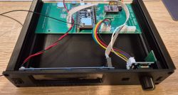
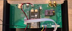
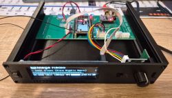
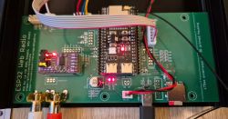
    I put the PCB together today. For a prototype, I'm pleasantly surprised. Everything I designed worked. USB works, SD card works. It "stood up" from the first switch on :) The whole thing fits elegantly into the printed case. I am therefore pleased to announce that the Eagle files as well as the Gerbery are tested and if anyone wants to, they can use and order "blind".

    View of the interior of a prototype device with a mounted PCB and wiring inside a case. .
    PCB with ESP32 and audio components for internet radio. .
    Prototype electronic device with an open case displaying mounted PCB, display, and connectors. .
    Close-up of an ESP32 Web Radio PCB with connected wires and components. .


    @gabar5 I see you are going for a similar solution with the Sony tuner I have prepared. Which tuner are you converting ?
  • #946 21480176
    robgold
    Level 20  
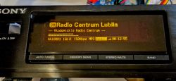
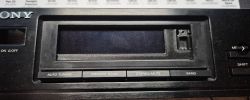
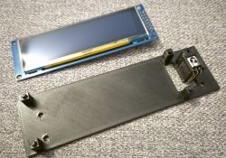
    @gabar5 take a peek at me on GitHub. Link Here you have the finished files of the frame for the display (mounting in place of the original) plus the front cap. The front cover/frame is designed in such a way that it "slips" into the housing, covering up the superfluous part of the OLED. Virtually anything can be used there - power supply, keyboard. A very nice conversion tuner.

    In TME there is an encoder with a long axle Link , which fits this tuner perfectly instead of the original switch/buttons from changing stations to this big knob. The board I've shown has leads for the keypad. In my case, I am just operating the keyboard in the ST-S120 conversion.

    Sony radio panel with OLED display showing Radio Centrum Lublin station. .
    Front panel of a Sony radio tuner with a screen cover. .
    OLED display and plastic frame .
  • #947 21480192
    gabar5
    Level 12  
    The culprit turned out to be, as you wrote, the ESP32 version, after uploading 3.0.5 the sound was found.
    @robgold thanks for the link, I managed to print the frame myself beforehand, not so professional but does the job. I left the encoder short, but made up a distance so that. the knob does not go too far and rub. I abandoned the idea behind the original power supply, brought out a 5.5x2.1 connector and a USB socket for power. I connected the RCAs to the PCM. I didn't move the buttons, as I'll mainly be controlling with the remote, if I'll be changing anything at all apart from switching on :) .
    I will still add a relay from the ESP8266 to connect to the Home Assistant, but only responsible for switching on, and the main switch will be as a switch detected by alternate state change.
    thank you very much for your help.

    PS. My wife asked if I will also make her such a radio for work :) .
  • #948 21480342
    DJCheester
    Level 26  
    Radio cool ;) I confirm this is why I also want to do an update of the analogue radio in my audio set.

    I am thinking intensively about this idea ;) .

    Question for you I need to change the pins so that the PCB I am designing based on the ESP32-S3 UNO

    https://www.elektroda.pl/rtvforum/topic4041603-900.html#21475806

    We have such declarations

    Code: Arduino
    Log in, to see the code
    .

    Which pins can be used as desired.

    As far as I know, the encoder can be connected to any GPIO and IR receiver.

    With regard to OLED, PCM and SD, is it possible to change anything in the connections?

    Of course, when you change the pins, you have to make a different declaration, but the idea is to make it work with new, different connections.

    Regards ...
  • #950 21480747
    robgold
    Level 20  
    Welcome,

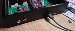
    I have finished the rear part of the case in the printed variant. I eliminated all screws, made the studs to match the holes in the PCB. This eliminates the need for threaded knurled bushings which cuts costs. The built-in micro-SD card slot on the PCB also seems to be a better solution as it is cheaper and in the case of the radio, it is reached in emergency situations. The whole thing looks like this:

    Back of radio casing with ports and PCB with connected cables. .
    Close-up of a PCB with electronic components and wires. .
    Rear panel of a black, printed case with antenna sockets and USB ports. .

    A set of files to print your own radio case can be found on GitHub -> Link .
    And if anyone would like to modify something, I have also uploaded the SKP (Sketch Up) files
  • #951 21481544
    gabar5
    Level 12  
    @robgold I'm guessing this is a draft version and you didn't care about the quality. If you wanted a nicer effect, I would recommend reducing the line width and printing the part rotated 180 degrees in the X or Y axis, adding supports of course. Leaving the current orientation, you can also use a different plate, such as carbon PET, so you can get an interesting texture (beware of the model peeling off, as the table needs to be at a lower temperature).
  • #952 21481905
    robgold
    Level 20  
    @gabar5 What do you mean "rotated 180 st" and why ? You may not be able to see it in the photo because the light came in that way, but I need to print with the flat part on the table because I have a textured board and I care about it. I know that this way the PCB mounts are printed in the least durable way but they don't carry loads you don't know what.

    This is what it looks like ultimately:
    Black plastic cover with holes, lying on a sheet with a printed schematic. .
  • ADVERTISEMENT
  • #953 21481971
    DJCheester
    Level 26  
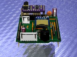
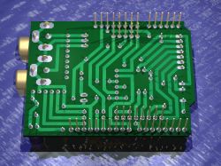
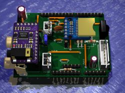
    Hello I have managed to design, in part, an overlay for the ESP32-S3-Uno which I bought and is on its way.

    Additional pads added - it remains a matter of accurate sizing as I sized these accurately based on the photo.

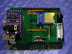
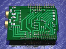
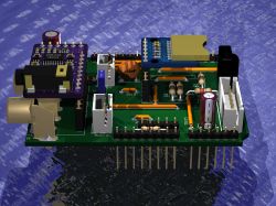
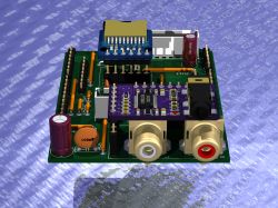
    Render of a PCB with various components, including an ESP32-S3-Uno module. .
    Visualization of a green printed circuit board with visible traces and gold pins.

    No encoder slot for the time being, I rather not envisage an encoder with me in this version, I don't have one fastened in the current version either, everything operates beautifully from the remote control.

    Also the PAM8403 power amplifier is missing there will only be a 3-pin(JST) and 2-pin(JST) audio lead for the PAM8403 module power supply - the module will be plugged in separately.

    As for the pins for OLED, SD and PCM, the ones declared in the software have been retained.

    This is the third version of the radio PCB ;) .

    When I refine it I will of course post it.

    Regards ...
  • #954 21481987
    gabar5
    Level 12  
    @robgold if that was the effect you wanted then that's cool, I personally prefer the finish on the top layer but sometimes the pei tile texture also gives an interesting effect
  • #955 21482020
    robgold
    Level 20  
    @gabar5 I don't know how good a printer you have and how it finishes your top layer for me it is nice but not amazing so to speak (I print on a Prusa MK4S), at work I have access to a Bamboo and it also finishes the top layer similarly. Can you imagine the amount of support under this whole panel as I would turn it ? :) It would probably make more sense to glue these mounts onto the PCB and put it together separately so as not to waste so much material.

    @DJCheester Did you deliberately block the slot with the IR receiver ? The card certainly won't fall out, but you can't pull it out easily either.
  • #956 21482034
    gabar5
    Level 12  
    All in all, for strength and aesthetics, you could print 'vertically' with a longer distance on the board and give adjacent supports under the protruding elements. An interesting procedure is to print the top layer of the support with petg at the pla model. It is easier to peel off the support. I print on A1 AMS and A1 mini.
  • #957 21482060
    robgold
    Level 20  
    @gabar5 Such I will agree that vertical printing has more strength however the consequence is less "round" holes as you need to calibrate the printer for the material in question so that those holes printed vertically are fixed circles rather than ovals. In this case, I'd rather have a round hole for the RCA sockets than mega-strength. Nobody is going to tear this PCB in the middle. Unless the display rebels :D .

    I like the textured structure. PLA unfortunately has a tendency to not hold dimension and shrink. You have to set up the printer specifically. I got the housing profile from PLA because I had some old black PLA and wanted to use it for something. If you have AMS it's easier for you to do material mixes. With me, unfortunately, it's a manual swap.
  • #958 21482404
    DJCheester
    Level 26  
    robgold wrote:
    @DJCheester You have deliberately blocked the slot with an IR receiver ? The card certainly won't fall out but you won't pull it out easily either.

    The module will be on longer goldpins the card will be above the sensor, this PCB is an experimental version for practicing on the ESP32 rather than building a finished radio, for this I have two previous PCBs.

    I am planning similarly to my colleague Robgold to mount another radio in retro hardware. However, for this I will need to learn a bit about the software. I'm hoping mate Robgold can help and get the hang of it.

    Here's how it will look...

    Experimental PCB with ESP32 module and audio components. .
    Experimental PCB with components for ESP32.
    Experimental PCB with electronic components, including RCA jacks and capacitors. .
    Image of an ESP32 module on an experimental PCB. .
    Green PCB with visible traces and electronic components, such as goldpins. .

    Greetings...
  • #959 21484900
    Sharki38
    Level 9  
    Good morning... I came across this radio project the other day and I have to say that I found it very interesting. Huge congratulations to the author and the people who are building their builds of this project. I would like to make my radio, but as I am a beginner, I would like to ask where to start. It is known that from buying parts, no less the heart of the circuit is the ESP32-S3.... but I'm looking for a version with an external antenna so that there is better WiFi coverage and, as you know, the N16R8 and here the essential part of my question. Which module to choose and where to look for original modules and do you have any good source for ESP32 on Aliexpress? Or are there any proven, let's say, ESP32 "fakes".... That go with this project. I am more concerned with the whole development board including the UART converter. Will such a module be okey:

    https://a.aliexpress.com/_EQNfzDi

    This module does not have the Espressif logo, but maybe someone is using it and is able to suggest that this module would be okey for this project. I apologise in advance for the perhaps mundane question, but I am new and the project is so interesting that I would like to make my own, and you have to start somewhere ;) .
  • #960 21485020
    gabar5
    Level 12  
    I picked up some from the drawer, probably the cheapest Chinese one without a logo and it works too :) .
    I've seen that the antenna can be soldered to the path, but without that I have coverage through 3 walls in a tin radio housing, where the phone already switches to 5G at that point.

Topic summary

The discussion revolves around building an internet radio and audio file player using the ESP32-S3 microcontroller. The project includes features such as an OLED display, Wi-Fi connectivity, and audio playback capabilities. Users share their experiences with hardware setup, including issues with pin configurations, library compatibility, and troubleshooting compilation errors in the Arduino IDE. Suggestions for libraries, such as ESP32-audioI2S and WiFiManager, are provided to enhance functionality. Participants also discuss the importance of proper wiring, capacitor usage for encoders, and the potential for adding features like DLNA support and a web management interface for radio station management. Several users report on their progress, share code snippets, and offer solutions to common problems encountered during development.
Summary generated by the language model.
ADVERTISEMENT