logo elektroda
logo elektroda
X
logo elektroda

LCR-T4 electronics components tester ATMega328 - Test and Review

TechEkspert 204720 647
ADVERTISEMENT
Treść została przetłumaczona polish » english Zobacz oryginalną wersję tematu
  • #151 16600223
    Anonymous
    Level 1  
  • ADVERTISEMENT
  • #152 16600713
    CMS
    Administrator of HydePark
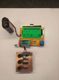
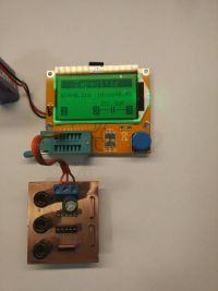
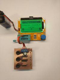
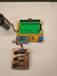
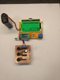
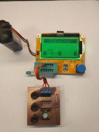
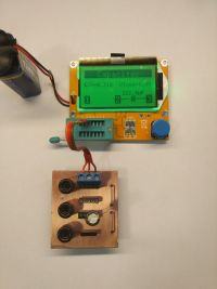
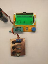
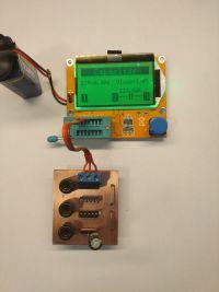
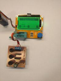
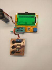
    I made a small extension to the tester and now I have quite a puzzle to solve. Look yourself. Pins 1 and 2 are connected and "doing" as pad 1 test, pin 3 is pad 2 test, pins 4 and 5 are connected and "do" for pad 3 test. And in all joints, except ARK and bananas, because these they are triple. These wires on the right side are copper wire coated with a 10? 3W resistor soldered on them to unload the capacitors before the measurement. And now the time for pictures, pay attention to which outputs the capacitor is connected to, where the measurement result is incorrect. LCR-T4 electronics components tester ATMega328 - Test and Review LCR-T4 electronics components tester ATMega328 - Test and Review LCR-T4 electronics components tester ATMega328 - Test and Review LCR-T4 electronics components tester ATMega328 - Test and Review LCR-T4 electronics components tester ATMega328 - Test and Review LCR-T4 electronics components tester ATMega328 - Test and Review LCR-T4 electronics components tester ATMega328 - Test and Review LCR-T4 electronics components tester ATMega328 - Test and Review LCR-T4 electronics components tester ATMega328 - Test and Review LCR-T4 electronics components tester ATMega328 - Test and Review LCR-T4 electronics components tester ATMega328 - Test and Review Normally, I would think that I have a faulty stand, but two different damaged ones are no longer an exaggeration. Please note that in the last two photos the capacitor is connected to other pins than the tester detects. a 220uF capacitor on pins 1-3, and the tester sees 25pF at 1-2. Who will be so clever and say what this beast is about? Maybe it measures the capacity of paths. But if so, why it does not go out equally, after all, all connectors are connected in parallel and the paths have the same length for each slot. Apart from the bananas, because each one has a different length, but I did not check on these joints.
  • #153 16600770
    vodiczka
    Level 43  
    Novile wrote:
    Because where do you write that an element does not enter the handles ?? Forgive but sorry, this is your defense line.
    Are you making a fool of yourself or are you trying to make me? Since, as you rightly wrote, I did not indicate that the element does not fit into the handles on what basis europtis he wrote:
    eurotips wrote:
    As the item does not enter the stand on pcb it is not connected to the feet by connecting cables
    instead of asking me how this capacitor connected :) . Did he see from a distance of over 300km as I was making a measurement or "in the dark" suggested that "I kept the cable in the paws" :?: Where does the infantile naming "cable" instead of "cord" come from? You emotionally defend your friend instead of reading comprehensively from posts 175 to 177.
  • #154 16600923
    Anonymous
    Level 1  
  • #155 16601707
    vodiczka
    Level 43  
    eurotips wrote:
    Most of the "strange" indications are the issue of the pins contact of the tested element. When testing an unknown element, it is worth inserting it into the stand twice, turning it 180 degrees second time.
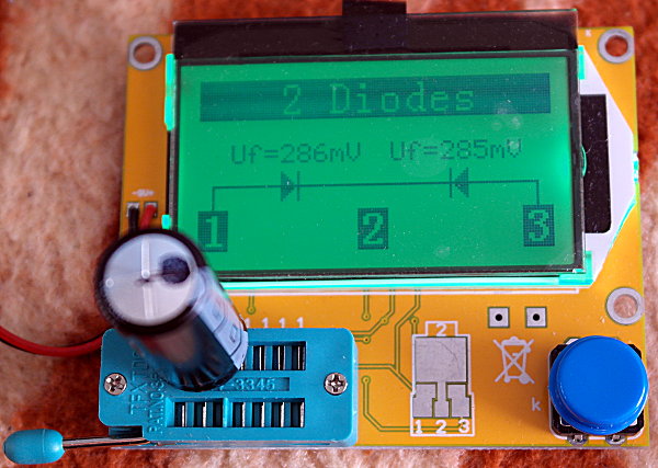
    If it's a matter of contacts, just insert it twice or three times in the same position. If the reversal by 180 degrees significantly changes the test result, for example from the transistor, the thyristor is made, and really it is a triac, the error lies in the way of testing. Returning to the German capacitor, which "appeared" at the first measurement as a duodode. Earlier (just after receiving the tester) I measured a dozen capacitors with a capacity of 10 nF to 4700 F, there were no surprises, then (repeated measurement of German and several others, not previously measured). That is why I consider the contact error unlikely.
  • #156 16644970
    vodiczka
    Level 43  
    vodiczka wrote:
    A curiosity about what a tester can do. At the first measurement of the old GDR capacitor from 1987. o. nom. 2200uF / 63V detected a double diode. The next capacitor with capacitance is correctly 2120uF. Is it possible that a long unused capacitor "pretends" two diodes connected in series cathode to the cathode?
    I probably discovered the reason for this strange behavior of the tester. Yesterday I measured the capacitor again and again pretended to be a double diode, also after the pins reversed. I looked carefully at the capacitor and noticed something that had previously escaped my attention. The capacitor has only been output + and - it is on an aluminum housing. The minus outlet is soldered to a brass washer pressed with an aluminum nut. Probably due to the influence of these metals (micro-cell), the result is false. When I moved this washer, the tester correctly identified the capacitor and measured its capacitance. Added after 6 [minutes]: Still a request. Maybe one of my colleagues would like to test the linear potentiometer. The tester visualizes its image as two resistors connected in series with the tap at the connection point. The visualization changes (guess how?) When the potentiometer is turned to the maximum left or right. At the end of the test results of the Mf-102 phono cartridge. As far as I remember correctly, the nominal resistance of the coils of one channel is 660? and the inductance is 550mH. I measured: L - 668? and 541mH; R- 638? and 595mH
  • ADVERTISEMENT
  • #157 16645515
    kkknc
    Level 43  
    Sometimes the capacitor identifies me as a resistor.
  • #158 16645607
    MiernikZKauflanda
    Level 20  
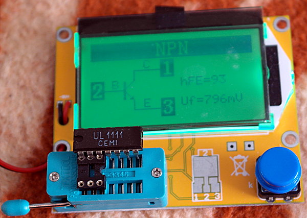
    And what interests me the most is what this tester showed on one of the "components" of UL1111 integrated transistors ... I just do not have to check because I do not have the meter: /
  • #159 16645626
    Rezystor240
    Level 42  
    MiernikZKauflanda wrote:
    And I am most interested in what this tester would show for one of the "components" of the UL1111 integrated transistors ...
    It's better to see if the logic gate will show.
  • ADVERTISEMENT
  • #160 16645658
    Adamcyn
    Level 38  
    MiernikZKauflanda wrote:
    And what interests me the most is what this tester showed on one of the "components" of the UL1111 integrated transistors
    Why do you ask? There are quite normal bipolar transistors.
    robiit1 wrote:
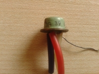
    .. Workshop "WN-T 1987r. gives the transistor data from this system: Uce = 15V, Ucb = 20V, Ueb = 5V, Icmax50mA, Ptot = 300mW, f = 500MHz.
  • ADVERTISEMENT
  • #161 16645866
    WojtasJD
    Level 43  
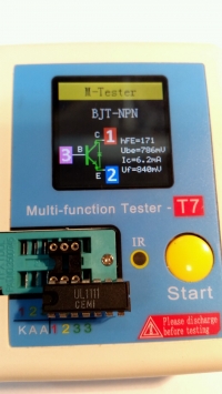
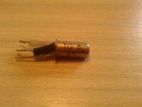
    Potentiometer like two resistors - in the extreme one of the resistors 0 ? 4700uF / 10V - left on the voltage of approx. 9 V pulls about 0.1 A and heats up. On the capacitance meter about 2.6 mF With new or "normally" used, not corpses, I like measuring C and ESR, and that's the most useful for me now. :D LCR-T4 electronics components tester ATMega328 - Test and Review UL1111 - measurement of one of the differential pair LCR-T4 electronics components tester ATMega328 - Test and Review and gates, as I understand from the series, e.g., 7400, require power so this meter will not work.
  • #162 16646640
    vodiczka
    Level 43  
    WojtasJD wrote:
    Potentiometer like two resistors - in the extreme one of the resistors 0 ?
    Theoretically you are right, but did you do the measurement as I asked? I will suggest - in my case the visualization is changing, not just the measurement result, which is not 0?. In one extreme position about 4? and in the other about 7?. 50k? potentiometer.
  • #163 16648312
    Stanley_P
    Level 28  
    Adamcyn wrote:
    MiernikZKauflanda wrote:
    And what interests me the most is what this tester showed on one of the "components" of the UL1111 integrated transistors
    Why do you ask? There are quite normal bipolar transistors.
    robiit1 wrote:
    .. Workshop "WN-T 1987r. gives the transistor data from this system: Uce = 15V, Ucb = 20V, Ueb = 5V, Icmax50mA, Ptot = 300mW, f = 500MHz.
    UL1111 - tester T7 yes, it is presumably detected as normal bipolar transistors. But t5 on terminals 12 (B), 13 (E), 14 (C) has a diode between E and C. And she is there, which can be checked with a diode tester in an ordinary multimeter :) It seems that by combining 13 (E) with the ground, so you can judge from the application note, LCR-T4 electronics components tester ATMega328 - Test and Review
    Quote:
    and gates, as I understand from the series, e.g., 7400, require power so this meter will not work.
    This type of testers are intended only for measurements of discrete elements, it was probably in this thread. It can not sensibly detect / measure even TL431 type circuits. Similarly in terms of operational amplifiers.
  • #164 16656242
    vodiczka
    Level 43  
    Two more points of interest of the tester, I suggest you check yourself. In both cases, three measuring points, as in the measurement of the voltage divider. 1. We measure two LEDs (not necessarily the same color) connected in series with a cathode-cathode (or anode-anode) and then a cathode-anode. 2. A rectifier diode connected in series with a 20? resistor
  • #165 16656429
    brofran
    Level 41  
    vodiczka wrote:
    Two more points of the tester's curiosities
    Stanley_P wrote:
    This type of testers are intended only for measurements of discrete elements
    Therefore, combinations of diode + diode, diode + resistor, ..... etc. will not give correct results.
  • #166 16656499
    E8600
    Level 41  
    So, without the elementary knowledge of electronics, the tester is of little use. I wonder how he would deal with germanium diodes or other elements rarely used today.
  • #167 16656531
    Rezystor240
    Level 42  
    E8600 wrote:
    I wonder how he would deal with germanium diodes or other elements rarely used today.
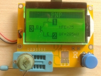
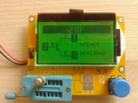
    I found a germanium transistor in my museum. Photos what the tester showed: LCR-T4 electronics components tester ATMega328 - Test and Review LCR-T4 electronics components tester ATMega328 - Test and Review The transistor is working :) Added after 12 [minutes]: Another transistor: LCR-T4 electronics components tester ATMega328 - Test and Review LCR-T4 electronics components tester ATMega328 - Test and Review Also working.
  • #168 16656717
    398216 Usunięty
    Level 43  
    E8600 wrote:
    So, without the elementary knowledge of electronics, the tester is of little use.
    And it's very good that it is. At least some residual logical thinking abilities will be useful. And the worst thing is that someone thinks that everything can be explained in one sentence and even a total layman can handle it ...
  • #169 16657025
    vodiczka
    Level 43  
    brofran wrote:
    Therefore, diode + diode combinations, ....
    And here my friend is wrong. When connecting the cathode to the cathode or anode to the anode, the result and its visualization are correct - the tester will show the duodiod, will correctly measure the Uf of each diode, which is easy to check by measuring them one by one. Once again, I recommend playing with various elements. Not only the result but also the visualization of the elements connected in series, can surprise you :)
    E8600 wrote:
    So, without the elementary knowledge of electronics, the tester is of little use.
    Like a multimeter. :) I read, for example, an electrode trying to measure transformer's "efficiency" by connecting a multimeter (in the current range) to the secondary winding.
  • #170 16657051
    CMS
    Administrator of HydePark
    vodiczka wrote:
    When the cathode is connected to the cathode or anode to the anode, the result and its visualization are correct - the tester will show the duodiod.
    Why would he show it differently. This is just a semiconductor connector, and the fact that it generates light in the way does not bother you. See what happens when you connect the diodes in parallel, but not K to K and A to A, but to the cross, A to K and K to A. I bet that he will show a transil, if one supports. I do not have a tester on hand, but I will say that I am interested in such a combination.
  • #171 16657324
    vodiczka
    Level 43  
    CMS wrote:
    Why would he show it differently.
    Ask a brofran :)
    brofran wrote:
    Therefore, combinations of diode + diode, diode + resistor, ..... etc. will not give correct results.
    CMS wrote:
    See what happens when you connect the diodes in parallel, but not K to K and A to A, but to the cross, A to K and K to A. I bet that he will show a transil, if one supports.
    I checked, box :) It shows what it should show, that is it identifies 2 diodes connected in parallel to cross, both Uf = 1.90V. Plus for the tester. With an AA and KK connection it shows one diode with Uf = 1.85V. With two different diodes (red and green), it also identifies correctly. Uf 1.57 and 1.90V respectively. In the serial connection, the AK does not identify the element (or identifies as a damaged duodiod) - the message "No, unknown or damaged part" while the serial connection BYP680 and the resistor 20? (with the tap at the connection point pinned in the pin) 2) also identifies as 2 diodes. The first one (actually a diode) connected to pins 1 and 2 Uf = 593mV. The second (virtual and actually a diode + resistor) inserted in pins 1 and 3, Uf = 741mv.
  • #172 16658466
    Stanley_P
    Level 28  
    Stanley_P wrote:
    This type of testers are intended only for measurements of discrete elements
    brofran wrote:
    Therefore, combinations of diode + diode, diode + resistor, ..... etc. will not give correct results.
    I meant that they are not suitable for diagnosing elements containing integrated structures - someone previously asked for logic gates (and I saw the testing of, for example, operational amplifiers through the eyes of the imagination, I do not know, maybe some processors? ;) ). In general, I have the impression that some of my colleagues have too high requirements for this type of device. I think everyone knows that there are no good universal adhesives ;) I believe - as I said in one of the first posts - that testers can really do a lot anyway, and if I had such a miracle 30 years ago, when I was actively involved in electronics (in the sense of designing something myself), I would probably be happy ceiling. But the times were different then, electronics too, not to mention the availability of parts. Does anyone, for example, remember to buy probably in the Scout Storage, sets of transistors, eg a'la BC107 / 177, without markings, so-called defective, probably discards from production? A few or a dozen in a one-two bag were usually completely damaged, the rest was suitable for amateur constructions. The tester would be ideal for "sifting" such elements, or numerous "from the demobil" at that time. Because now my practical contact with electronics mainly consists of repairs of certain equipment, replacement of elements only for new ones, after a few weeks of having the tester, I found the usefulness in two, maybe three cases: 1. checking new element (eg transistor, capacitor) in front of its installation. Rarely because rarely, but it happened that the "thread tentacle" straight from the factory packaging was damaged, which, that I write so, introduced additional confusion and extended the repair process. 2. ESR measurement in electrolytes, although usually if the capacitor is already considered "suspect" and dismounted, it is replaced with a new one (i.e. p.1) 3. still sometimes a bit of fun, which is nice, showing friends familiar to the topic ;) But less and less. Greetings. PS Regarding germanium elements - it was already in earlier posts. Measures, It just measures.
  • #173 16658592
    Dydelmax
    Level 39  
    Out of curiosity, I connected the tester to the KORAD KD3005D laboratory power supply to check the impact of tester power supply on the results it generates. As the measuring element, an electrolytic capacitor was used Nippon Chemi-Con SXE 1000?F 25V . After connecting to the power supply, the tester was calibrated at 9V supply voltage - I did this calibration after each power loss (when the battery is changed, calibration is also performed). The results below:
    Power supply voltage Vbat (V) Capacity (?F) ESR (? ;) Vloss (%)
    9.0 V 8.92 volts 996.9 0.08 1.20
    8.8 V 8.73 V 999.8 0.08 1.20
    8.6 V 8.53 V 999.8 0.08 0.90
    8.4 V 8.32 V 999.8 0.08 0.90
    8.2 V 8.12 V 999.8 0.08 0.90
    8.0 V 7.93 V 999.8 0.08 0.90
    7.5 V 7.44 V 999.8 0.08 0.90
    7.0 V 6.93 V 996.9 0.08 1.20
    6.50 V 6.52 V 1015 0.07 0.09
    6.04 V 6.68 V 1015 0.07 0.09
    5.8 V 6.75 V 1018 0.03 0.90
    5.6 V 6.83 V 1024 0.03 0.90
    5.4 V 6.91 V 1027 0.08 0.90
    5.2 V 6.97 V 1030 0.08 0.90
    5.0 V 7.07 V 1033 0.09 0.90
    4.8 V 7.19 V 1040 0.01 0.90
    4.6 V 7.32 V 1044 0.01 1.20
    4.4 V 7.48 V 1051 0.00 1.20
    4.33 V 7.55 V 1055 0.00 0.90
    Below 6.5 V, the message "Peplace the battery!" Appears (original spelling). Theoretically, you can not measure, but ... after the voltage is reduced to 6.04 V, measurements are possible. Below 4.33 V, the tester shuts down during the measurement, while below 4.15 V the tester goes out even when displaying the result. Generally, at a voltage lower than 5 V, the display becomes unreadable.
  • #174 16658603
    Jawi_P
    Level 36  
    Dydelmax wrote:
    (calibration is also done when the batteries are changed)
    It is interesting. Why the creator anticipates calibration after replacing the battery, if it is still stabilizer. In total, it should not be needed. But the "experiment" is interesting.
  • #175 16658615
    HD-VIDEO
    Level 43  
    And what does this power measurement do. At 7V the stabilizer stops working properly, in addition the meter uses 5V supply voltage as a reference
  • #176 16658664
    gulson
    System Administrator
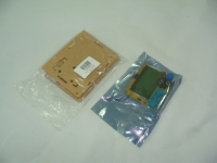
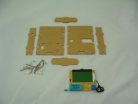
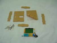
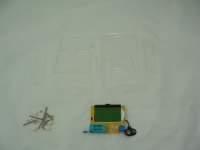
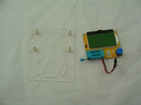
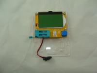
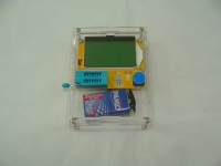
    Folding the tester housing: LCR-T4 electronics components tester ATMega328 - Test and Review LCR-T4 electronics components tester ATMega328 - Test and Review LCR-T4 electronics components tester ATMega328 - Test and Review LCR-T4 electronics components tester ATMega328 - Test and Review LCR-T4 electronics components tester ATMega328 - Test and Review LCR-T4 electronics components tester ATMega328 - Test and Review LCR-T4 electronics components tester ATMega328 - Test and Review
  • #177 16658711
    398216 Usunięty
    Level 43  
    The housing prevents using the tester to check SMD components.
  • #178 16658740
    krzysztofh
    Level 29  
    gulson wrote:
    Folding the tester housing: LCR-T4 electronics components tester ATMega328 - Test and Review LCR-T4 electronics components tester ATMega328 - Test and Review LCR-T4 electronics components tester ATMega328 - Test and Review LCR-T4 electronics components tester ATMega328 - Test and Review LCR-T4 electronics components tester ATMega328 - Test and Review LCR-T4 electronics components tester ATMega328 - Test and Review LCR-T4 electronics components tester ATMega328 - Test and Review
    I bought such a housing and, unfortunately, the attached white sleeves are probably 11.5mm long and are too long and the attempt to twist the enclosure ends with the permanent depression of the tester button. It needs to be replaced with 10mm bushings.
  • #179 16658746
    gulson
    System Administrator
    The person who played with this did not report anything like that. The sleeve in the test copy was 10mm. I do not know how in others.
  • #180 16661477
    gumisie
    Level 43  
    Hello. I ordered, the points went, I am waiting for delivery. Dear Gentlemen, after all this is not a device that may be used to smoke for us. Reading the following statements:
    E8600 wrote:
    So, without the elementary knowledge of electronics, the tester is of little use.
    And for china, a folk hairdresser would need a tiller.
    krzysztofh wrote:
    I bought such a housing and, unfortunately, the attached white sleeves are probably 11.5mm long and are too long and the attempt to twist the enclosure ends with the permanent depression of the tester button. It needs to be replaced with 10mm bushings.
    Replace?. We created hammers for the first six months at school (Kasprzak) with a file from a piece, a roller with a diameter of 5cm. With full respect for precision mechanics, but a real electronics enthusiast for this hobbyist with this 1.5mm would not write something like that. After all, this is a gadget that has the right to be useful at the bivouac with grandchildren. Greetings.

Topic summary

The LCR-T4 electronics components tester based on the ATMega328 microcontroller is a versatile, low-power device powered by a 9V battery, drawing 12-15mA during measurement and 20nA in sleep mode. It automatically detects component types and lead configurations, measuring parameters such as resistance, capacitance (up to 47,000µF), inductance, diode voltage drop, transistor type and pinout, and ESR. Calibration involves shorting the test leads and using a known capacitor above 100nF. The tester supports testing of discrete components including resistors, capacitors, diodes, bipolar and field-effect transistors, and thyristors, though it struggles with integrated LM series voltage regulators due to their complex internal structures. Accuracy is generally sufficient for amateur and workshop use, with some noted measurement deviations, especially in low resistance and inductance readings. The device features a white LCD display, with some users comparing it to yellow LCD variants and color display models with built-in batteries. The ZIF socket is a known weak point, prone to contact issues and limited to thin leads; users recommend alternative housings and socket modifications for durability. The ribbon cable connecting the display is fragile and non-replaceable separately, requiring careful handling. The tester is available as a DIY kit with open-source firmware and as ready-made units, purchasable from Chinese suppliers and local Polish sellers, with prices around $30 or 25-40 PLN depending on housing and shipping. Shipping damage to displays has been reported due to insufficient packaging, prompting suggestions for improved protection. Firmware variations exist, affecting features like contrast adjustment and component recognition. The device is highly regarded for its ease of use, broad functionality, and value for money, making it a popular gadget among electronics hobbyists. Community discussions include suggestions for further development, housing designs, and integration of the elektroda.pl logo for uniqueness.
Summary generated by the language model.
ADVERTISEMENT