Hello for the versatility of PCBs but this is just a figment of my imagination.
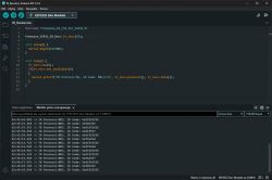
I started comparing materials - on the author's PCB the OLED is connected to different ESP32 pins than on yours ?
Did you change this during the modification and the current softy supports these changes ?
On the author's there were pins 3,46, 8,9 and on yours it is from 38 to 42 ??
As for the connectors for the OLED for the time being I put this 2x8 pin under the 3 inch screen
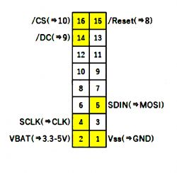
.
Greetings ...
Added after 1 [hours] 11 [minutes]: Hello, for now a sketch of a single sided PCB without polygons - for now there are connections and this to check I will sit down when there will be a moment again - through-hole components, I have added a PAM8403 2x3W amplifier module with speaker outputs so that the radio can be used on its own 5V amplifier power supply next to it I will add some more filter capacitors. the main filtration is designed for ESP as well as a 4-pin small PCB with a USB power socket
I made the PCB for now, first version, it is possible that there are some mistakes, I will just check it.
On the PCB
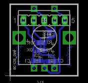
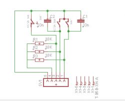
2x5pin connectors from two encoders
1x5pin connector from directional buttons
IDC16pin - for the OLED display (I have given up on one connector for now)
6-pin - memory card module
4-pin - under ESP power socket module
2x chinch - audio output
2x2pin - added 2x3W amplifier and speaker output
That's it
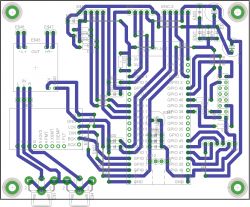
.
Greetings ..,
Added after 1 [hour] 56 [minutes]: Board more roughly embraced from colleague's schematic, added 2x3W PAM8403 amplifier in Chinese version and two capacitors at the amplifier.
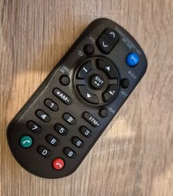
As for the software is there the possibility of programo vol+/- ? because this would take care of the radio as a standalone device, for example after adding the speakers it would function as a kitchen radio.
The board after my inspection - I will still check the connections tomorrow at ease (with a fresh mind) and when the modules arrive I will check the pin spacing so that everything fits.
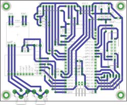
.
I'll do the board, we'll see maybe there won't be too much interference (I'm not an audiophile and for me it will be important how it already plays and receives)
The board virtually looks like this
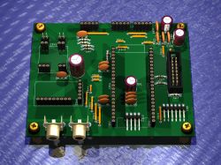
Where the horizontal gold pins are, there will be a USB socket (4-pin) and a memory card socket (6-pin)
For my purposes I will make a single sided PCB looking like this
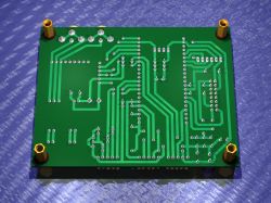
.
Alternatively, you will be able to order for yourself in China with polygon
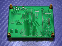
That's the end of the work for today, I'm waiting for the modules I will verify the pin spacing before etching and the correctness of the paths tomorrow.
Greetings ...


