logo elektroda
logo elektroda
X
logo elektroda

Internet radio and audio file player on ESP32-S3

MAJSTER XXL 100734 1227
ADVERTISEMENT
Treść została przetłumaczona polish » english Zobacz oryginalną wersję tematu
  • #541 21433491
    DJCheester
    Level 26  
    Hello, mobile data is on, so the net should be there, so I understand that I have to put these three files on the main directory of the card?

    Tell me because on arduino 1.8.19 I have serial monitor from this board and here on 64bit on 2.1.1 IDE I have this

    Screenshot of Arduino IDE software with program code for ESP32 module. .

    I am now uploading the 3.15 version.

    After uploading via arduino soft, do I have to assign the access point again from the beginning or not ?

    Greetings ...
  • ADVERTISEMENT
  • #542 21433609
    robgold
    Level 20  
    The Arduino sometimes has its "freaks" when it comes to the serial monitor. You have to shut it down completely and fire it up again. Unfortunately. Such is the "super" environment.
    When it comes to WiFi settings and programming, it all depends if you have the option set: "Erase all Flash....."
    If Enable then unfortunately yes. Disable this option then all WiFi settings will remain.


    Screenshot of Arduino settings with Erase All Flash Before Sketch Upload set to Disabled. .
  • #543 21433694
    DJCheester
    Level 26  
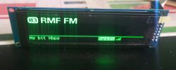
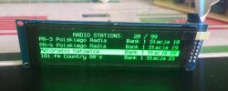
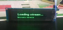
    I have uploaded V3.15

    LCD display showing RMF FM on channel 03 .
    LCD screen displaying a list of radio stations. .
    LCD display showing Loading stream... Meloradio Katowice. .

    Banks reads from sd connects but seems to not download data.

    This is strange because the hotspot connected to the computer normally shares the net.

    I'll try clearing and uploading again later with the access point setting.

    For now, thanks and best regards....
  • #544 21433699
    MAJSTER XXL
    Level 29  
    @robgold I have the handling of a fresh card done, if there are no station_nr and bank_nr files needed they are created, then only the last bank and station number data are read from them.
  • #545 21433720
    robgold
    Level 20  
    @MAJSTER XXL

    I have checked, it actually works correctly. Question did you notice that ESP gets "hiccups" when it can't retrieve the time ?
    The function reading from the NTP server "chokes" the void loop. You probably need to add a delay there so that this UDP connection is able to retrieve the time.

    @DJCheester
    Post what you get on the terminal. There's a ton of "debug" information there that will help determine the problem.


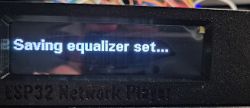
    As part of today's "fun moment", I added a function that saves the Equalizer settings to an "equalizer.txt" file.
    The file is read at startup. If it is not on the SD card then the filter values will be set to 0.
    Updated v3.15 file on GitHub.

    To save the filter settings, while in the Equalizer menu after setting the filters, confirm them with the OK/ENT button on the remote control. We will then get a message on the display. Otherwise, we will change the settings, but after restarting the radio we will read the previously saved ones or, in the absence of a file, the values 0,0,0.


    Screen displaying Saving equalizer set... message on an ESP32 Network Player device. .
  • ADVERTISEMENT
  • #546 21433771
    DJCheester
    Level 26  
    Hello from the series I only have this

    Code: Text
    Log in, to see the code


    I will now upload with the option to delete the access point and configure again.

    I don't know what's going on but when it writes now that it runs the server to configure the one with the IP in the serial monitor it doesn't find my phone or computer ESP32 Radio ???

    Maybe something is wrong with my ESP ??
    Or something is compiling wrong.

    Or maybe it's not what I installed from this site ??
    https://dl.espressif.com/dl/esp-idf/
    What is it actually for - isn't it the same as what arduino downloads when adding ESP32 boards?

    And when the ESP32 server appears, it literally disappears after a while ??
    I do not know what could be the reason ??

    Greetings ....

    Greetings ...
  • #547 21433804
    robgold
    Level 20  
    If it tells you ESP is starting a portal on the terminal then touch the ESP antenna with your finger and see if it finds you ESP32 Radio on the phone.
    I have one module like this that has just such coverage problems.
  • #548 21433838
    DJCheester
    Level 26  
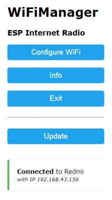
    Well that's the problem, after touching the antenna it shows up on the phone and on the computer, I did that from the phone I permanently let the hotspot go and on the computer I connected to the ESP and set up the access point (holding the antenna of course) and immediately it showed up.

    WiFiManager interface for ESP Internet Radio with buttons Configure WiFi, Info, Exit, Update and information about connection to Redmi. .

    Radio mastered game thank you all project great - now I have to put the toy away for a week or so (but good thing it's up and running).

    I'll fix the PCB in eagle and make it available in the days for use - someone asked about the PAM8403 plays nicely for this little thing.

    Thanks guys, I'm off to play with my new toy - it's just this finger that's bugging me - just a pensioner who doesn't know ESP must have got a faulty one ech....

    Regards ...
  • #549 21433850
    robgold
    Level 20  
    I will tell you that if you take it out of the PCB and plug in ONLY USB it will find it. I suspect stresses (microcracks?) on the PCB or a faulty component in the antenna matching circuit. I'll have a moment to desolder this circuit and check it with an RLC meter, I've already removed the metal "cap" from mine but I didn't see anything worrying under the microscope.
  • #550 21433866
    DJCheester
    Level 26  
    Well I'll tell you I don't want to find it either because when I tried to set it up that's exactly how I did it with no PCB just ESP hooked up to the USBC.

    Nothing will have to buy another one - the important thing is that the trails are blazed.

    By the way, I've noticed that the ESP32, when I supply power to my PCB from the USBC connector, no voltage goes out to my PCB and on the ESP32 module it also says 5V in, which is why the display didn't work when I was programming it - because I have it supplied with 5V from the USB on my PCB. It is possible to use 3.3V then it would work, but is the stabiliser on the ESP not too "sweaty".

    Greetings....

    Added after 10 [minutes]:

    Thanks Robgold 😀
    Beautiful case.

    As I have you on the links I will ask about the remote.

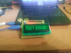
    I once made myself such a remote control tester on an Arduino UNO

    It displays the code like this

    Display showing remote code 0xFD52AD against a laptop background. .

    On the serial monitor I have some more info see in a moment I will add
    Code: Text
    Log in, to see the code


    How does this relate to your codes written in the script ?

    Code: Arduino
    Log in, to see the code


    Greetings ...
  • #551 21433904
    robgold
    Level 20  
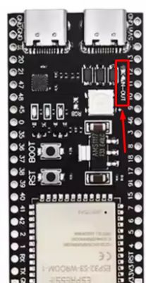
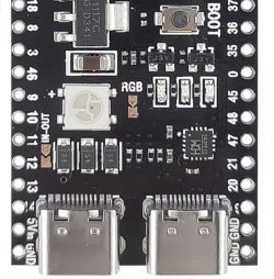
    At the top of the module near USB-OTG you have a jumper unsoldered. This is why 5V does not come out of the module with a pin.

    Electronic module with an unconnected USB-OTG jumper highlighted. .

    Code 0xFD52AD is a code let's call it in "RAW" format. You see the reading in LSB-MSB form along with bytes in negation for packet control.
    At the terminal the Radio sends all the information. Here an example: 9D6228D7 is what you see in your tester. Then you have the inverted bytes to MSB-LSB and the address and command cut out.

    NEC code OK:9D6228D7 MSB-LSB: EB1446B9 ADR:B9 CMD:14
    debug-- pulse 9ms:8986 4.5ms:4575 1690us:1691 690us:598
  • #552 21433917
    DJCheester
    Level 26  
    Well, I didn't know that (anyway, as I wrote, I've seen ESP32 for the first time).
    And tell me if it is possible to read my codes from the remote control so that they match the radio (rewrite them or write them differently)
    And that big RGB diode or RGB jumper, if I unsolder it on the module, it will not burn my eyes ;)

    Thank you ;)
  • #553 21433926
    robgold
    Level 20  
    Clicking with the remote control, the radio will not respond but codes will appear on the terminal, such as here:

    NEC code OK:FF629D MSB-LSB: B946FF00 ADR:0 CMD:46
    debug-- pulse 9ms:9052 4.5ms:4597 1690us:1719 690us:628

    You press a button and write down on a piece of paper (or immediately in the sketch) what ADR and CMD the button has.
    Then, in place of the given command you substitute 0xADRCMD, for example 0x0046
  • #554 21433950
    DJCheester
    Level 26  
    O ingenious 😀

    It's on to the next sitting, the important thing is that there is progress, and lots of it.

    It's still as if you could tell if the jumper on the ESP named RGB is from the diode the big one ?

    And the rst button is known reset and what does boot do ?

    Sorry for the layman questions 😀

    No more tests for today because my finger is already stiff - I'm ordering a second ESP

    Regards...
  • ADVERTISEMENT
  • #555 21433967
    MAJSTER XXL
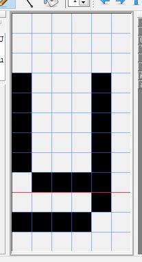
    Level 29  
    @robgold could you correct the lowercase "y" so that its bottom is raised by one row of pixels, i.e. so that it fits like the lowercase "g" ?
  • #556 21434061
    robgold
    Level 20  
    Do you have similar observations to mine ? Apparently as many as 256x64 pixels and in reality every line is worth its weight in gold :)

    Code: C / C++
    Log in, to see the code


    Example of font at 256x64 pixel resolution .
  • #557 21434067
    wirbud
    Level 13  
    DJCheester wrote:
    Well, that big RGB diode or RGB jumper if I unsolder it on the module it won't burn my eyes
    .
    next to the diode is where the 2 pads are (RGB) but this time there is a thread of print between them. To turn the diode off just cut this thread. You can always put a blob of tin and the dida can burn your eyes out again! (I tried in yoRadio to put it out, four GPIO ardes I used and it still lit up after a few seconds. )
    Circuit board with electronic components, including an RGB LED and two USB-C ports. .
  • #558 21434072
    robgold
    Level 20  
    The situation with the diode is interesting. It seemed to me that in ESP32 S3 devkit1 this diode is a digital diode that requires whole commands to be sent to it to make it light up (at least that's how it is with me). It should go off after the flash is wiped. And here it comes out as if it were a regular RGB zipped to the GPIO.
  • ADVERTISEMENT
  • #560 21434102
    simw
    Level 27  
    robgold wrote:
    it looks like it would be a regular RGB zipped to GPIO.
    .
    Unplug the power supply, it has to go off because these are WS2812Bs.
    If you don't unplug then the diode is simply "latched".
  • #561 21434115
    robgold
    Level 20  
    @CodeBoy

    If you have the soldering equipment (HotAir) and a bit of skill, it's cheaper to buy the "Chinese" from Ali and the original Espressif module at TME. You will be able to close in 40-50zł. There is a chance that you will find a good piece, then 20-25zł, if not then in TME the 16R8 module costs 28zł gross. You must also remember that with 2MB of PSRAM, according to ESP documentation, you have QSPI memory, not OPI. Although in this application it does not matter, but the configuration of the sketch is different.

    Link .
    Link .
  • #562 21434120
    MAJSTER XXL
    Level 29  
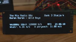
    @robgold beautifully, the question is whether any of the characters still stand up or down too much and ooze onto the adjacent lines? I think it was just the little 'y' that was too lowered.


    LCD display showing information about a radio station and wind conditions. .
  • #563 21434129
    robgold
    Level 20  
    @MAJSTER XXL, I've looked at the whole font. I think it's just the letters q,p - vertical dashes.

    And back to the subject of ESP quality. I bought a "bag" of IR receivers (VS1838B) on Allegro, at 1.25zl for 2pcs, and I also found one that "worked" but did not keep the output times completely correctly. I bet that nothing is wasted in China. They pack as they go, even the production waste.
  • #564 21434283
    TechEkspert
    Editor
    Perhaps it would be possible to do a version of the project with ethernet connectivity?
  • #565 21434558
    DJCheester
    Level 26  
    Welcome ;) .

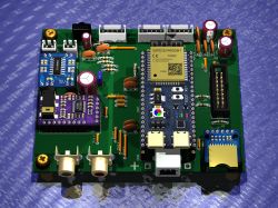
    As promised I am making my PCB design files available

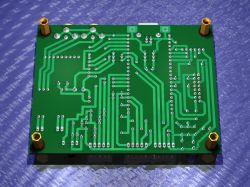
    PCB design with ESP32-S3-WROOM-1 module and JST connectors.
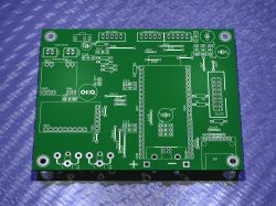
    Visualization of a single-sided PCB with green laminate and copper traces. .
    PCB design with various connectors and components .
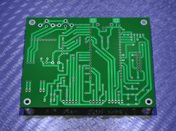
    Printed circuit board design with green laminate and white tracks. .

    The board for software by friend robgold v3.14 (v3.15 will also work, but there is no keypad connector as of v3.15). The board should also work with author's software MAJSTER XXL (I have not tested it) has JST slots for second encoder and keypad used in this software.

    A jumper on the PCB powers the PAM8403 amplifier.

    Robgold soft running with the help of a colleague (thank you for your support)
    On PCB corrected connections (as declared in the software)
    Radio plays and starts after correct ESP programming and configuration.

    NOTE: Not tested remote control for now - lack of time probably will run this further on Saturday.

    If someone would like to order a ready-to-use board from a company, the pads in RCA connectors should be corrected (I will do it as soon as I find a moment after the radio is fully operational) There are round pads and there should be oblong ones (I had such a library)

    In the case of thermo-transfer and making the board by yourself (one-sided), the type of pads does not affect the assembly, because you can re-drill the holes to longitudinal ones (in the case of ready-made boards from China with metallized holes, it would be useful to do it the way you need)

    A pdf file ready for thermal transfer is also included in the package.

    Best regards....
  • #566 21435162
    wirbud
    Level 13  
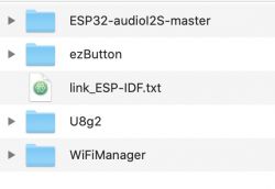
    To colleagues with compilation problems..... Yesterday I made the enty attempt to compile. As described by robgold - (ver 3.15) - I placed the libraries from the directory in the Libraries directory in Arduino (not Arduino15). As usual, there was a rash of errors. I came up with the idea that since it was bothered by duplicate libraries I removed from the sketches directory all those that had their versions installed by Espressif 2.0.17 (in the Arduino15 directory). Shot in 10. Compilation without error !
    So much should be left in /Arduino/Libraries
    List of directories in the Libraries folder for Arduino. .
  • #567 21435285
    DJCheester
    Level 26  
    The question I have is if I want to go crazy and buy such a larger OLED for this radio

    https://pl.aliexpress.com/item/1005006861743547.html

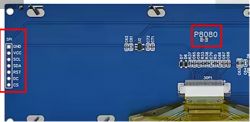
    Here on the back there are no jumpers on how to set the data bus in 3.12 you soldered a resistor on 4SPI

    https://ae01.alicdn.com/kf/Sad9d8069f69e47cd81331791955ccb9c3.jpg_960x960.jpg

    And how to do it here ?

    Do you have any information because it is a shame to risk 200PLN if it turns out that it will not work ?

    Greetings ...
  • #568 21435328
    robgold
    Level 20  
    On the back as far as I can see you have a jumper called 8080, the SPI connector on the left. Presumably when you unsolder this jumper it goes into SPI mode.
    The driver is the same, it should work without any software changes. Someone here already asked about this display and was about to order it. Look for it in this thread.


    Close-up of the back side of a display circuit board with highlighted SPI connector and P8080 jumper. .
  • #569 21435335
    DJCheester
    Level 26  
    That was me, I asked 😀

    Only at the time I didn't yet know about the configuration on display....

    I preferred to ask.

    Thanks and best regards...
  • #570 21436480
    DJCheester
    Level 26  
    One question

    Is there an option to have the volume (level) saved like an equalizer to a txt file on the card ?

    The idea is to make the radio remember the last volume level settings.

    And second question, the ESP module has bluetooth, at least that is what it says here

    https://sklep.msalamon.pl/produkt/plytka-esp3...MIvYDywKy-iwMVY6iDBx3P0hqrEAQYBiABEgJk2fD_BwE

    Have you considered adding the option to listen to songs e.g. from your phone ?

    For example mode radio/sdmp3/bt

    Greetings ...

Topic summary

The discussion revolves around building an internet radio and audio file player using the ESP32-S3 microcontroller. The project includes features such as an OLED display, Wi-Fi connectivity, and audio playback capabilities. Users share their experiences with hardware setup, including issues with pin configurations, library compatibility, and troubleshooting compilation errors in the Arduino IDE. Suggestions for libraries, such as ESP32-audioI2S and WiFiManager, are provided to enhance functionality. Participants also discuss the importance of proper wiring, capacitor usage for encoders, and the potential for adding features like DLNA support and a web management interface for radio station management. Several users report on their progress, share code snippets, and offer solutions to common problems encountered during development.
Summary generated by the language model.
ADVERTISEMENT