logo elektroda
logo elektroda
X
logo elektroda

Internet radio and audio file player on ESP32-S3

MAJSTER XXL 106242 1246
ADVERTISEMENT
Treść została przetłumaczona polish » english Zobacz oryginalną wersję tematu
  • ADVERTISEMENT
  • #812 21462044
    robgold
    Level 20  
    @Slawek K.
    I agree, but that excess PCB is due to the slot in the printed (175mm) or aluminium case (160mm). It's not my extravagance, but a deliberate procedure. Otherwise you will save on PCBs, but you will have to foresee a bonded mount with a snap pin, like in the old PC for motherboards.

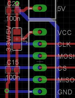
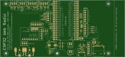
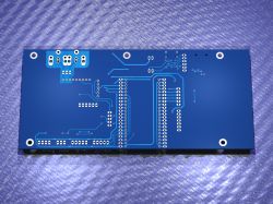
    The voltage selection jumper for the cards has flown in, but I'm not completely convinced. Those off-the-shelf SD modules are moderately suitable for ESP. They have pull-up resistors on almost every line, on top of that converting the signal to 5 V to then go back to a 3.3 V interface. As for the converter, I don't really see where to plug in that MCLK pin. It would have to be instead of the JOY, but this @wirbud would have to confirm that using GPIO16, 17 or 18 is possible.


    Fragment of a printed circuit board design with visible traces and pin labels. .
  • #813 21462069
    wirbud
    Level 13  
    It is possible to contribute to some sort of group order - or does it not make sense as the pcb with shipping from China will cost the same per head anyway?
    I ask because I have never ordered a pcb.... back in the days of communist Poland... ;-) Chlorine and micro drill....
  • #814 21462126
    ArturAVS
    Moderator
    If an order exceeds 5 pieces, it is already a commercial order and VAT will be added.
  • #815 21462209
    DJCheester
    Level 26  
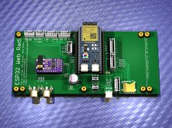
    Hi robgold if you want send the brd file I will make a render so you can see what's what on the PCB ;)

    Added after 3 [hours] 26 [minutes]:

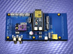
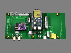
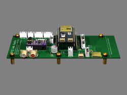
    PCB board ;) by colleague robgold ;) .

    Render of an ESP32 Web Radio PCB with various components and connectors. .

    Render quickly - sockets you can see a colleague used different than I have 3D models but the general view is ;)

    Regards ...
  • #816 21462508
    efi222
    Level 19  
    DJCheester wrote:
    Render on quick - sockets you can see a colleague used other than I have 3D models but the general idea is
    .
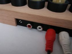
    The RCA sockets should be as close to the edge of the board as possible. I mounted them in another project. The rear wall of the case at this point should be as thin as possible. With a tin case there is no problem, but with plastic cases or 3D prints it is worth paying attention to this. I gave 1mm and it is ok.
    Below is an example of the undo on a veneered 3D print with a 4mm wall
    Close-up of RCA jacks mounted on a wooden enclosure with connected cables.
  • ADVERTISEMENT
  • #817 21462880
    robgold
    Level 20  
    @DJCheester , I've uploaded the PCB and schematic files to GitHub, cos on this visualisation the USBC slot has gone awry and the SD card slot is 180st reversed. Also correct that big electrolyte, on the visualisation it has reverse polarity. If you can, make a visualisation of the new board.

    @efi222 in case of RCA sockets it is enough to make a bigger hole in the case and the socket itself can even be flush with the case surface. That's how they did it in older equipment. Especially with sockets like the one in the project mounted directly to the PCB it is not possible otherwise. They are very short.

    Remember that this is actually a simple breakout/test board and not a target PCB. I'm just fed up with the contactor board starting to have a life of its own.


    ESP32 Web Radio PCB design with highlighted components. .
  • #818 21462916
    DJCheester
    Level 26  
    Yes I know I saw the imperfections, just used different libraries than me will improve tomorrow as for the uSD slot do you have that close to the leg on it physically have that slot ?
    I was sent to work today and there was no time to get these details right.

    Also check the footprints from Chinch because they must have elongated pads and mine fit perfectly on the connectors and the ones on the schematic are probably too long, you would have to make a printout and check.

    Regards...
  • #819 21462963
    Szaryczlowiek83
    Level 7  
    Hello.
    I have a sound problem and have no idea what is wrong. Have I messed something up or do I have a banged up pcm board.
    This is the simplest radio I have found. If anyone has the time and inclination could post a sketch on the board and write back if it plays. Pinology as in the design so nothing needs to be rewired.
    In place of '***' you need to enter the network name and password, and install "WiFiManager_Generic_Lite".

    Ps. Which project works without the card and encoder?


    PPs. never mind I got the pins wrong
  • #820 21463264
    robgold
    Level 20  
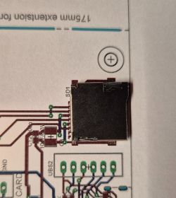
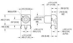
    @DJCheester Yes, I have such SD card sockets even a whole packet for £3 from Ali :) This is a standard microSD socket with spring latch. The chinch sockets are tested. The diameter of the hole is important and the PAD itself is how you like it. It is easier on production to make round holes than to mill for a tin. Here is a PDF for these sockets Link I have still fine-tuned them a bit. I generally try to use my libraries and draw myself the components because then there are surprises when the PCB arrives.


    MicroSD slot mounted on a printed circuit board layout. .
  • #821 21463277
    DJCheester
    Level 26  
    Ok this will be an opportunity to refresh your povray macros and add more 😀

    For the purposes of this project, I was making an ESP and USB-C module

    See before you send this socket to china

    https://allegro.pl/oferta/gniazdo-rca-cinch-do-druku-katowe-zolte-10605418327

    Because there you have to have longitudinal pads and this your library under Chinch will probably not fit because I made my PCB from mine and when I inserted it on your PCB the pads did not match. Unless you use other Chinch e.g. the ones with plastic ?

    If something happens, I will improve mine tomorrow and I can send it to you.

    Regards...
  • ADVERTISEMENT
  • #822 21463292
    robgold
    Level 20  
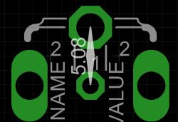
    The pads for these plates can also be round, the important thing is that the diameter matches. I have corrected some distances in the library.

    Electronic circuit layout with hexagonal and oval pads, with a 5.08 measurement between them. .
    Technical drawing with dimensions of an electronic component, indicating length, width, and diameter. .
  • #823 21463377
    wirbud
    Level 13  
    Great request - robgold - would you make your myoptions.h available for yoradio - with you the display was running normally - it's not possible for my SSD1322 to be so "politically" correct ;-) .
    (did you compile on 1.8.19 (2.0.17) or already in 2.3.4 (3.0.7.... 3.1.1) ?) Thanks a lot.
  • #824 21463395
    DJCheester
    Level 26  
    Side pad is 2.54 better to give oblong holes

    Technical drawing of a detail with dimensions. .

    Greetings...
  • ADVERTISEMENT
  • #825 21463453
    robgold
    Level 20  
    @wirbud I have already uploaded the myoption.h file for yoRadio here. Below you have the configurations. I compiled on an old Arduino 1.8.19

    Code: C / C++
    Log in, to see the code
    .
  • #826 21463879
    DJCheester
    Level 26  
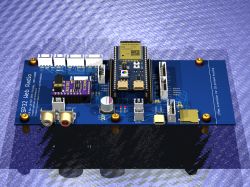
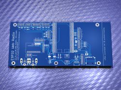
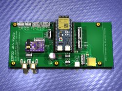
    Here is the render ;)

    Render of a board with an ESP32 module, chinch sockets, and various electronic components. .
    Render of ESP32 Web Radio board with added chinch sockets and shifted pads.
    Rendered PCB of ESP32 Web Radio with adjusted chinch socket pads. .
    PCB render with traces and holes for chinch sockets. .

    I applied my chinch sockets to this board you can see how the pads from the sockets are offset. I have corrected the rest.

    Greetings ...
  • #827 21465100
    robgold
    Level 20  
    This came out fantastic :) If you don't mind I will upload to myself on GitHub as a visualisation. Also on GitHub is the latest version there are corrected those cinch sockets.
  • #828 21465145
    DJCheester
    Level 26  
    Ok then today I will make a render with the revised - final version.
    I don't see a problem with you posting renders on Github.
    After all, I also use the project and the radio works fine with me.

    Any additional requests e.g. resolution, camera angle and PCB angle, PCB colour?

    Greetings....
  • #829 21465270
    robgold
    Level 20  
    If you can get some grey solid background and green laminate because that's the pcb I ordered.
  • #830 21465288
    DJCheester
    Level 26  
    It will be as you write 😀
    Greetings...
  • #831 21465298
    ArturAVS
    Moderator
    Finally all the goodies have arrived for me, two displays (3.12 inch 256x64 SSD1322, and 128x64 SSD1309), a transmitter board, and a couple of different modules from ESP32-S3 (I'll upload pictures later). Once I get the whole thing up and running on the contactor, I'll get on with the board.
  • #832 21465539
    efi222
    Level 19  
    @ArturAVS
    "Thick" investment... I'm curious about the compact version. Good luck :) .
  • #833 21465776
    DJCheester
    Level 26  
    Robgold I don't see an update - last modified 2 days ago

    Screenshot of a GitHub repository with the ESP32 Web Radio Evo3 project. .

    Greetings ...
  • #834 21465817
    marek003
    Level 40  
    I found the project very interesting.
    Praise to the authors of the code :) .
    Great work.
    I'm going to play/understand/combine with this a bit :) .

    However, I have long since "switched" to VS Code and the platform IDE so ... therefore a request (for the future and in my spare time) to the code authors @robgold and @MAJSTER XXL: - I know Arduino doesn't require it but even for the sheer art of writing code - declare a procedure/function/variable in the code beforehand before you use it because not all languages allow such nonchalance :) .
    It took me about half an hour to move procedures and functions around in my colleague @robgold's code (so far without trying to understand the code) - well, but the important thing is that the project compiled. :) .

    Unfortunately I can't check if it works yet because I'm waiting for the board in this version. I have a pair of ESP32-S2's but according to the information to the ESP32-audioI2S library (Audio.h) it is designed for dual-core microcontrollers e.g. "S3" so I'm not going crazy :( .

    For those who want to run the project "under platformio", information that you just need to add 3 libraries to the project in the patformio.ini file (available under platformio)
    lib_deps =
    olikraus/U8g2
    tzapu/WiFiManager
    arduinogetstarted/ezButton

    The ESP32-audioI2S library, on the other hand, should be added yourself (preferably to the "lib" directory because in the platformio "environment" the 2022 version is available, probably 2.0.7, and the authors of this thread use functions that are in version 3.0.12h.

    And here is also an interesting fact because in the project of colleague @robgold there is just version 3.0.12h, and on the official website of the author of the library there is version 3.0.12 with the letter "e", and the next (current) version is already 3.1.0.
    At the same time, I guess it is now in the process of being made/improved by the library author because after downloading it, errors still pop up in the library itself.
    By the way, it is also possible to connect via platformio "directly" to the data on the GitHub pages, but as I mentioned, the latest library version 3.1.0 is then downloaded (and gives errors in itself), and I (at least for now) cannot enter a reference in the platformio.ini file to a library with a specific lower version that is posted on GitHub.

    Finally, many thanks again to the code authors for sharing their knowledge.

    Ps. If anyone would like to run/compile the project in platformio, attached is the version of my colleague @robgold (I hope he won't be offended) with the routines and functions moved around so it can compile without errors. Of course you still need to add the libraries as I wrote earlier and everything should compile.
  • #835 21465823
    DJCheester
    Level 26  
    New (old) renders

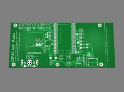
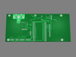
    Render of an ESP32 Web Radio board with various modules and components on a green background. .
    Render of a green printed circuit board (PCB) on a gray background. .
    Render of a PCB with various components on a gray background. .
    Rendered ESP32 Web Radio PCB on a gray background. .
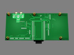
    Green printed circuit board with connections on a gray background. .

    PCB colour and background (grey), in Hi-Res resolution

    Regards ...
  • #836 21465898
    robgold
    Level 20  
    @marek003
    I freely admit that I often write myself "something off the top of my head" in notepad++ and then just paste it in, and don't always pay attention to whether it landed before the potential callout. Thanks for the conversions to Platformio. To me personally, this environment does not appeal. It is just as "underdeveloped" as Arduino. I'm trying to approach it for the umpteenth time now and can't seem to get to like it. As far as the library is concerned, I have manually pasted 3.1.0d from the author's test repository. If I remember correctly, there was a patch for FLAC files. There is a previous version left on github. Keep an eye out for newer versions of core ESP32. There is a lot of description on the audio library page regarding DMA and i2s problems.
    And why did you call the dimmer functions dimmer xxx ? :) .

    @DJCheester
    The board and schematic and gerber files can be found here: Link .
    On GitHub, will package this into a single ZIP in a moment. The board has been produced. I'm waiting for the package to arrive.

    @ArturAVS
    What are you planning to design the PCB in ? I'm waiting with patience, maybe you'll get ahead of me because somehow I don't have the verve for this PCB-SMD version with just the ESP module.
  • #837 21466009
    ArturAVS
    Moderator
    @robgold KiCad. I need to think carefully so that I can prototype at home. Only when I get it up and running will I order the boards.
  • #838 21466012
    DJCheester
    Level 26  
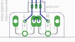
    Hi - robgold you provided a link and I am using it but there files are from two days ago and when I open the BRD there are old versions of the chinch sockets.

    PCB schematic with audio-out connection and chinch sockets. .

    If this is what you ordered then these metal chinch sockets will not fit

    Regards ...

    Added after 36 [minutes]:

    Hello for those who will be assembling tiles for themselves according to the Robgold version.

    Greetings ....
  • #839 21466083
    DJCheester
    Level 26  
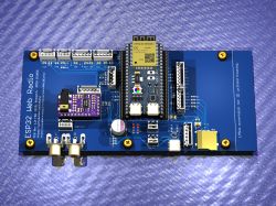
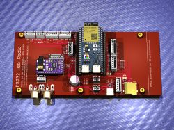
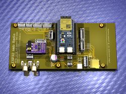
    Examples of PCB colours


    Green PCB with components for ESP32 Web Radio. .
    ESP32 Web Radio PCB with electronic components on a blue background. .
    PCB with an ESP32 module on a metallic surface. .
    Close-up of an ESP32 Web Radio PCB with various components and connectors. .

    Greetings ...
  • #840 21466118
    MAJSTER XXL
    Level 29  
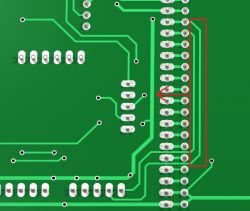
    @robgold I wouldn't push with those paths between the pads from the ESP32, you can safely switch outside the module and it will be more aesthetically pleasing and safe, you can even do without crossing those paths.

    Close-up of a green PCB with marked traces and solder points. .

    In general I have a request to anyone who can help with figuring out the proper init and control of my new OLED display with the SSD1363 driver via the I2C bus, nice 256x128pix screen, but it looks like there are some babes in the library from this SSD1363.
    I have exactly the same problem as in this link, identical static noise on the screen:
    https://github.com/olikraus/u8g2/issues/2298

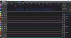
    My analyser shows communication, but in my opinion something is misaligned here:

    Logic analyzer application window showing I2C signals for OLED operation. .

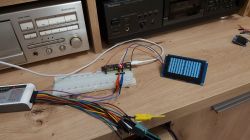
    because I have a screen like this all the time:


    Electronic setup with an OLED display showing interference. .

    I have connected the reset pin as a test and it executes it before init - it does nothing,
    request to have a look at the file in the library:
    https://github.com/olikraus/u8g2/blob/master/csrc/u8x8_d_ssd1363.c

    below link to the driver manual:
    https://admin.osptek.com/uploads/SSD_1363_0_10_to_Ri_Tdisplay_withcommandtable_aa469a71c2.pdf

    currently my test sketch uses this builder, but I checked on all of them - no change:

    Code: C / C++
    Log in, to see the code
    .

    still below a breakdown of what the analyser spits out with comments from AI, but you can see that something doesn't match here with the manual, in general I don't see a command to turn on the display after init, before init there is 0xAE, while 0xAF- never even appeared to me such a byte in the logs in over 17000 lines, it is strange:

    Code: C / C++
    Log in, to see the code
    .

    even when I added offhand an additional command to turn on this display and got the correct ACK nothing happens.

Topic summary

The discussion centers on the development of an internet radio and audio file player based on the ESP32-S3-WROOM-1 module, featuring a custom-designed prototype PCB with OLED display and user controls including rotary encoders and buttons. Key challenges addressed include pin spacing discrepancies in the ESP32-S3 module footprint, integration of Wi-Fi connectivity with dynamic station list updates, and handling of Polish character encoding on the OLED display. The project uses Arduino IDE (version 2.3.2) with ESP-IDF support and requires enabling PSRAM. Audio playback supports MP3, AAC, and FLAC streams, with the ESP32-audioI2S library recommended over the incompatible Audio library. Users reported issues with SPI MISO pin assignment causing bootloader conflicts, resolved by reassigning MISO to pin 35. The project incorporates WiFiManager for network configuration, EEPROM and SD card storage for saving last played station and settings, and includes plans for tone control via an external KA2107 equalizer and a CS8673 amplifier module. Problems with encoder input stability and memory limitations for Bluetooth A2DP on ESP32-S3 were noted. The community suggested alternatives like KaRadio and ESP32-MiniWebRadio projects. Debugging tips include serial terminal logs for HTTP errors and flash memory erasure to resolve boot loops. The project is open-source on GitHub, encouraging forks and modifications. Additional features under development include browser-based updates, directory navigation, and potential audio recording to SD card.
Summary generated by the language model.
ADVERTISEMENT