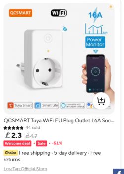
Hi. This is a look at a LoraTap branded Tuya-based EU WiFi smart plug/socket with power/energy metering. The model number is SP800WJ-EU. The official product page is here https://www.loratap.com/products/sp800wj-eu where it can also be purchased, but mine came from Ali Express at a lower price. Much cheaper if you're eligible for a Welcome Deal.
First we'll look at the product, then open it up, take it apart and solder the relevant parts up for flashing to OpenBeken, an open source Tuya replacement firmware. This conversion will cut the device off from any cloud servers for total control locally with or without HomeAssistant (and other IoT control platforms) integration.
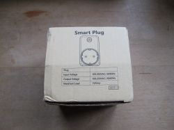
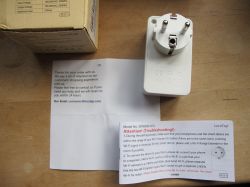
Packaging, box content, external product pictures:
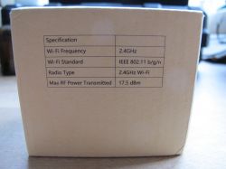
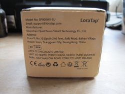
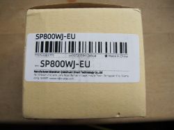
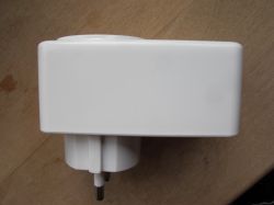
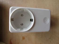
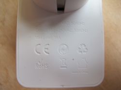
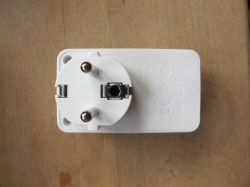
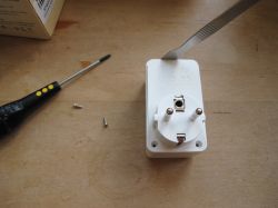
To get inside the device, the two cross-head screws on the underside need to be removed and the snap-fit casing pried open with a thin spudger
With the case apart there'll be some connections between the main parts stopping complete separation.
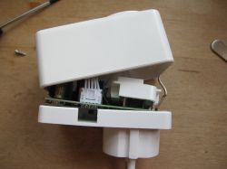
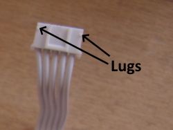
Pushing the little white lugs at the left and right of this connector allows the connector to be pushed upwards using something with a thin wedge, like a flat screwdriver or the edge of the spudger if narrow enough
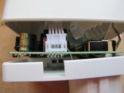
With that separated:
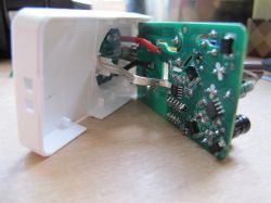
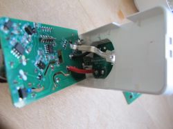
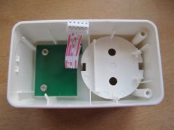
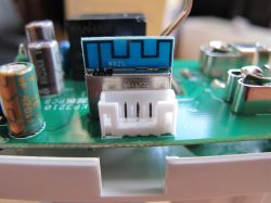
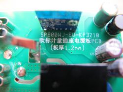
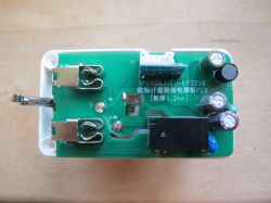
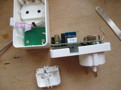
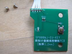
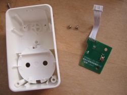
The ribbon cable went to a separate PCB where the LED and button are soldered, which itself can be freed by removing the two screws
Sticking up from the main PCB is the module we're interested in - the WB2S. Tuya WB2S has a Beken BK7231T chip under the metal RF shield.
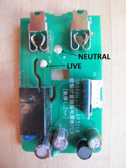
To free the main PCB completely, so we can access the WB2S properly, the mains live and neutral wires need to be de-soldered. I achieved this with a dab of flux on each solder blob and then heating each with a soldering iron until the solder melted, allowing the wires to be removed
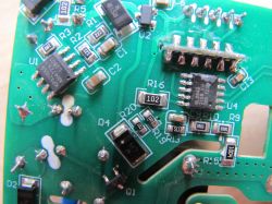
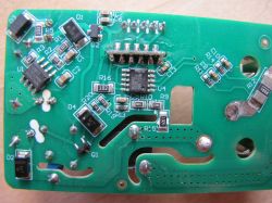
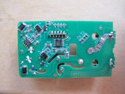
The WB2S RX/TX/3.3V and Ground points are easily accessible with the module kept in place, so no need to remove the whole module from the mainboard.
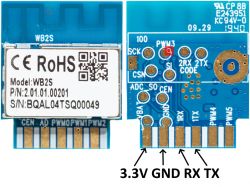
Solder those 4 up with some short thin wires
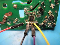
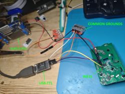
And connect as follows to your USB-TTL adaptor and external 3.3v power supply (USB-TTL's own 3.3v line will most likely not be enough for successful firmware backup and flash).
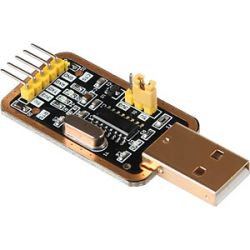
WB2S RX -> USB-TTL TX
WB2S TX -> USB-TTL RX
WB2S 3.3V -> Ext 3.3v PSU
WB2S GND -> USB-TTL GND and Ext 3.3v PSU GND
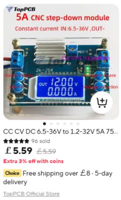
My PSU is a basic hobbyist XL4015 with LCD from Ali Express
With Easy Flasherrunning, BK7231T selected and the latest OpenBeken BK7231T firmware downloaded (EF does this for you), the backup of factory firmware and flash to OpenBeken can be started. Power on the PSU to begin the process. If the reading/writing fails, try lowering the baud rate and checking your wiring is sound and short. Ensure there is continuity between common grounds and all other points with the USB-TTL and PSU powered off.
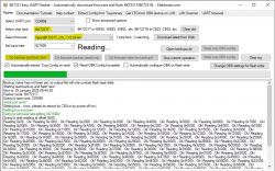
More flashing example steps: https://github.com/openshwprojects/BK7231GUIFlashTool
Your factory firmware will be backed-up to BK7231GUIFlashTool-v5\backups subdirectory. eg:

If possible, avoid pairing with the Tuya app at all so your wifi credentials are not present in the backup. These can remain even if the device is reset/removed from the app.
When flashing is complete and after an off/on of power, the OpenBeken AP broadcasts:
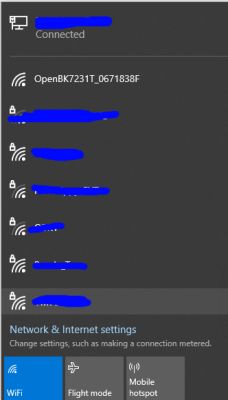
Join the AP to find OpenBeken gives you a client IP of 192.168.4.100. You can then browse to 192.168.4.1 to begin setup of OpenBeken.
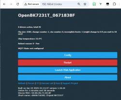
From this point you can configure OpenBeken to join your wifi, setup the template to control the device (button, relay, LED), configure MQTT and Home Assistant discovery, configure power monitoring etc, just like Tasmota.
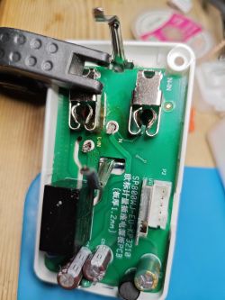
To put the device back together it is simply the reverse of the dismantle procedure, which should have been noted and remembered with care. One tip though, the live and neutral wires are a pain to line up and solder back, so I suggest soaking away with the solder from the holes on the main PCB first, poking the ends of the wires through, then soldering back up from the top with flux/solder as normal. eg:
Further configuration and general information, including how to discover the configuration specific to this device (LED GPIO, relay GPIO etc) are better served by guides that already exist:
How to automatically configure GPIO of OpenBeken device? Tuya Config template extraction, BK7231
Easy Home Assistant Discovery Pairing for BK7231T, BK7231N, BL602, XR3, W800, W600, etc. - OpenBeken
BK7231T/BK7231N WiFi, MQTT, template and IP configuration at flash time via UART - OpenBeken flasher
BK7231 datasheet, pinout, programming, specification, wiki (BK7231T, BK7231N)
How to script automatic switching off of the relay after a certain time in OBK without Home Assistant
Many more guides and information pages:
https://www.elektroda.com/rtvforum/forum517.html
https://www.youtube.com/@elektrodacom
https://github.com/openshwprojects/OpenBK7231T_App?tab=readme-ov-file#introduction
For this device, the LoraTap SP800WJ-EU, the following template will configure the basic LED, button, relay and power monitoring functions
Notes
UART TX2 P0 boot log
Firmware version 1.3.5 - CloudCutter exploitable: https://github.com/tuya-cloudcutter/tuya-clou...r/devices/loratap-sp800wj-eu-plug-v1.3.5.json
Unpaired storage area:
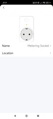
Tuya app screenshots
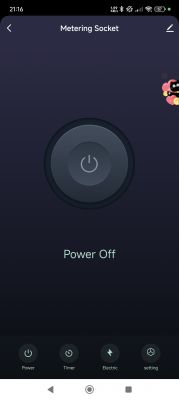
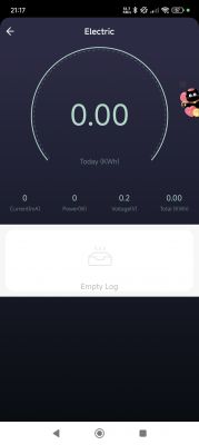
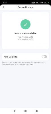
Factory backup Tuya_LoraTap_SP800WJ-EU_Plug_(schemaID-000002zjt3)_keym9qkuywghyrvs_1.3.5.bin https://github.com/openshwprojects/FlashDumps/tree/main/IoT/BK7231T
Additionally, this is only the second BK7231T with BL0942 chip in the device list, the first has the same template: https://www.elektroda.com/rtvforum/topic4041210.html
I am wondering if I could maybe turn this device into a test thing for BL0942 testing on any platform. I could route out RX/TX/GND/VCC as a minimum for use with any module- safe as long as the module is powered solely from the plug (?), no shared ground. Of course the wires on the WB2S PCB pads would need to be secure. Thoughts?

First we'll look at the product, then open it up, take it apart and solder the relevant parts up for flashing to OpenBeken, an open source Tuya replacement firmware. This conversion will cut the device off from any cloud servers for total control locally with or without HomeAssistant (and other IoT control platforms) integration.
Packaging, box content, external product pictures:


To get inside the device, the two cross-head screws on the underside need to be removed and the snap-fit casing pried open with a thin spudger

With the case apart there'll be some connections between the main parts stopping complete separation.

Pushing the little white lugs at the left and right of this connector allows the connector to be pushed upwards using something with a thin wedge, like a flat screwdriver or the edge of the spudger if narrow enough


With that separated:


The ribbon cable went to a separate PCB where the LED and button are soldered, which itself can be freed by removing the two screws


Sticking up from the main PCB is the module we're interested in - the WB2S. Tuya WB2S has a Beken BK7231T chip under the metal RF shield.
To free the main PCB completely, so we can access the WB2S properly, the mains live and neutral wires need to be de-soldered. I achieved this with a dab of flux on each solder blob and then heating each with a soldering iron until the solder melted, allowing the wires to be removed


The WB2S RX/TX/3.3V and Ground points are easily accessible with the module kept in place, so no need to remove the whole module from the mainboard.

Solder those 4 up with some short thin wires

And connect as follows to your USB-TTL adaptor and external 3.3v power supply (USB-TTL's own 3.3v line will most likely not be enough for successful firmware backup and flash).

WB2S RX -> USB-TTL TX
WB2S TX -> USB-TTL RX
WB2S 3.3V -> Ext 3.3v PSU
WB2S GND -> USB-TTL GND and Ext 3.3v PSU GND

My PSU is a basic hobbyist XL4015 with LCD from Ali Express

With Easy Flasherrunning, BK7231T selected and the latest OpenBeken BK7231T firmware downloaded (EF does this for you), the backup of factory firmware and flash to OpenBeken can be started. Power on the PSU to begin the process. If the reading/writing fails, try lowering the baud rate and checking your wiring is sound and short. Ensure there is continuity between common grounds and all other points with the USB-TTL and PSU powered off.

More flashing example steps: https://github.com/openshwprojects/BK7231GUIFlashTool
Your factory firmware will be backed-up to BK7231GUIFlashTool-v5\backups subdirectory. eg:

If possible, avoid pairing with the Tuya app at all so your wifi credentials are not present in the backup. These can remain even if the device is reset/removed from the app.
When flashing is complete and after an off/on of power, the OpenBeken AP broadcasts:

Join the AP to find OpenBeken gives you a client IP of 192.168.4.100. You can then browse to 192.168.4.1 to begin setup of OpenBeken.

From this point you can configure OpenBeken to join your wifi, setup the template to control the device (button, relay, LED), configure MQTT and Home Assistant discovery, configure power monitoring etc, just like Tasmota.
To put the device back together it is simply the reverse of the dismantle procedure, which should have been noted and remembered with care. One tip though, the live and neutral wires are a pain to line up and solder back, so I suggest soaking away with the solder from the holes on the main PCB first, poking the ends of the wires through, then soldering back up from the top with flux/solder as normal. eg:

Further configuration and general information, including how to discover the configuration specific to this device (LED GPIO, relay GPIO etc) are better served by guides that already exist:
How to automatically configure GPIO of OpenBeken device? Tuya Config template extraction, BK7231
Easy Home Assistant Discovery Pairing for BK7231T, BK7231N, BL602, XR3, W800, W600, etc. - OpenBeken
BK7231T/BK7231N WiFi, MQTT, template and IP configuration at flash time via UART - OpenBeken flasher
BK7231 datasheet, pinout, programming, specification, wiki (BK7231T, BK7231N)
How to script automatic switching off of the relay after a certain time in OBK without Home Assistant
Many more guides and information pages:
https://www.elektroda.com/rtvforum/forum517.html
https://www.youtube.com/@elektrodacom
https://github.com/openshwprojects/OpenBK7231T_App?tab=readme-ov-file#introduction
For this device, the LoraTap SP800WJ-EU, the following template will configure the basic LED, button, relay and power monitoring functions
Code: JSON
Notes
UART TX2 P0 boot log
Code: Text
Firmware version 1.3.5 - CloudCutter exploitable: https://github.com/tuya-cloudcutter/tuya-clou...r/devices/loratap-sp800wj-eu-plug-v1.3.5.json
Code: Text
Unpaired storage area:
Code: JSON
Code: Text
Tuya app screenshots


Factory backup Tuya_LoraTap_SP800WJ-EU_Plug_(schemaID-000002zjt3)_keym9qkuywghyrvs_1.3.5.bin https://github.com/openshwprojects/FlashDumps/tree/main/IoT/BK7231T
Additionally, this is only the second BK7231T with BL0942 chip in the device list, the first has the same template: https://www.elektroda.com/rtvforum/topic4041210.html
I am wondering if I could maybe turn this device into a test thing for BL0942 testing on any platform. I could route out RX/TX/GND/VCC as a minimum for use with any module- safe as long as the module is powered solely from the plug (?), no shared ground. Of course the wires on the WB2S PCB pads would need to be secure. Thoughts?
Cool? Ranking DIY


