logo elektroda
logo elektroda
X
logo elektroda

Qiachip Smart Switch - BK7231N / CB2S - interior, programming

p.kaczmarek2 64296 288
ADVERTISEMENT
Treść została przetłumaczona polish » english Zobacz oryginalną wersję tematu
  • #181 20232827
    omelchuk890
    Level 11  
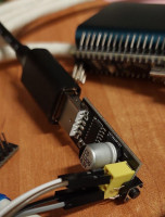
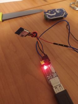
    We perform all connections to the USB adapter from the first post.
    I am using a board to connect the esp-01.
    Qiachip Smart Switch - BK7231N / CB2S - interior, programming20221012_0..117.jpg Download (103.79 kB)
    Installing python, for W7 the latest version is 3.8.10
    https://www.python.org/downloads/windows/
    When installing, note Add python 3.5 to PATH.

    Next, go to https://github.com/OpenBekenIOT/hid_download_py
    Green "CODE" button, Download ZIP.
    Qiachip Smart Switch - BK7231N / CB2S - interior, programming2022-10-12...-24-25.png Download (96.38 kB)
    I moved the archive to the root of the system disk I have, unpacked it, renamed it to hid_download_py, deleting the text "-master".
    There should be no attachments, i.e. by opening C:\hid_download_py there should be files and several folders at once.

    We go to the address https://github.com/openshwprojects/OpenBK7231T_App/releases
    Download the file BK7231N -> UART Flash-> OpenBK7231N_QIO_x.xx.xx.bin
    I created the folder BK7231 in the root of disk E, transferred the downloaded file to it.

    It remains to flash.
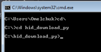
    Running the command line cmd.exe
    Going to the root of the disk: cd\
    I go to the directory with the program: cd hid_download_py
    Qiachip Smart Switch - BK7231N / CB2S - interior, programming2022-10-12...-53-38.png Download (3.35 kB)
    By this point, it is already necessary to know which port number the TTL-USB converter has.
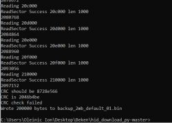
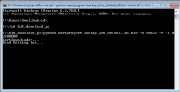
    I read the firmware, I have com-port #32, with the command: python uartprogram backup_2mb_default_01.bin -d com32 -r -l 0x200000
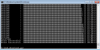
    After pressing "enter", I briefly connect CEN and GND, the firmware is read and the file specified in the command is created in the hid_download_py folder.
    After the inscription Getting BUSY ... we connect CEN and GND for a moment. If nothing has started within two to three seconds, repeat cen + gnd.
    Qiachip Smart Switch - BK7231N / CB2S - interior, programming2022-10-12...-37-57.png Download (10.3 kB)
    Qiachip Smart Switch - BK7231N / CB2S - interior, programming2022-10-12...-53-58.png Download (10.8 kB)
    After reading, we load the necessary file with the command: python uartprogram E:\BK7231\OpenBK7231N_QIO_1.12.103.bin --unprotect -d com32 -w --startaddr 0x0
    where E:\BK7231\OpenBK7231N_QIO_1.12.103.bin the path to the file and its name.
    the procedure is the same as when reading.
    Qiachip Smart Switch - BK7231N / CB2S - interior, programming2022-10-12...-58-17.png Download (12.97 kB)
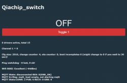
    Let's move on to testing...
    Qiachip Smart Switch - BK7231N / CB2S - interior, programming2022-10-12...-06-04.png Download (21.86 kB)
  • ADVERTISEMENT
  • #182 20232855
    gowthaml
    Level 7  
    @p.kaczmarek2 I am using my own Wi-Fi credentials method and I need mDNS to resolve ip addresses of the device .
  • #183 20234827
    kajarit
    Level 6  
    kajarit wrote:
    p.kaczmarek2 wrote:
    Ah ok @kajarit , I mistaken your post with @gowthaml
    Maybe your UART to USB converter has not enough current capability? Can you show photos? Have you tried powering it from external LDO 3.3V?


    Powering it through the "golden" CH340G which is - in theory - able to provide 150mA according to specs.

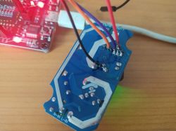
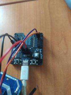
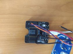
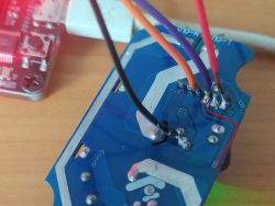
    Qiachip Smart Switch - BK7231N / CB2S - interior, programming Qiachip Smart Switch - BK7231N / CB2S - interior, programming


    Still no success, I'm trying to debug the code to find some clue why it can't write the firmware...
  • #184 20235362
    gowthaml
    Level 7  
    @kajarit While flashing firmware you need to ground the RST pin of cb3s and when flashing tool waiting for device for flashing you need to remove the ground of the RST pin it will start flashing.
  • #185 20236155
    kajarit
    Level 6  
    gowthaml wrote:
    @kajarit While flashing firmware you need to ground the RST pin of cb3s and when flashing tool waiting for device for flashing you need to remove the ground of the RST pin it will start flashing.


    Sure, I do it that way, so it starts with:
    Quote:
    UartDownloader....
    programm....
    Getting Bus...


    Then I connect GND to CEN (3), then it continues:
    Quote:
    Gotten Bus...
    Erasing
    Writing
    WriteSector 1 Failed


    Any other ideas?
  • #186 20238113
    gowthaml
    Level 7  
    @kajarit what command you are using to flash?
  • #187 20251379
    kajarit
    Level 6  
    gowthaml wrote:
    @kajarit what command you are using to flash?


    For flashing I use OpenBekenIOT/hid_download_py

    Backup FW

    This is working, however I was told to ignore the CRC check error message at the end.
    python3 uartprogram backup_2mb_default.bin -d /dev/tty.usbserial-1420 -r -l 0x200000 -b 115200


    Upload FW

    I've tried with the following QIO versions:
    - OpenBK7231N_QIO_1.12.55.bin
    - OpenBK7231N_QIO_1.12.106.bin

    With these different parameter name usage:
    python3 uartprogram ../OpenBK7231N/OpenBK7231N_QIO_1.12.55.bin -u -d /dev/tty.usbserial-1420 -w -s 0x0 -b 115200

    python3 uartprogram ../OpenBK7231N/OpenBK7231N_QIO_1.12.106.bin --unprotect -d /dev/tty.usbserial-1420 -w --startaddr 0x0 -b 115200
  • #188 20252165
    kajarit
    Level 6  
    I've succesfully flashed the OpenBK7231N_QIO_1.12.106.bin firmware using another computer.
    It seems a good-old ThinkPad is better for this purpose than a MacBook Pro 8-)

    Now I have to re-solder the previously cut tracks between the MCU and the CB3S to check if everything is fine...
  • #189 20252615
    p.kaczmarek2
    Moderator Smart Home
    Good job. So you only used different PC, but the same USB to UART dongle and it worked? Well, that's a fault scenario that I haven't experienced yet.
    Helpful post? Buy me a coffee.
  • #190 20253678
    gowthaml
    Level 7  
    @p.kaczmarek2 Is there any possible of porting mdns or can you help me to use lwip/mdns ?

    Added after 21 [minutes]:

    kajarit wrote:
    I've succesfully flashed the OpenBK7231N_QIO_1.12.106.bin firmware using another computer.
    It seems a good-old ThinkPad is better for this purpose than a MacBook Pro 8-)

    Now I have to re-solder the previously cut tracks between the MCU and the CB3S to check if everything is fine...


    @kajarit its not system issues , its due to baudrate issues try using different boardrate using your mac pro it will be flashed.
    If you get 'write sector failed', this can also be a mis-communication, so lower the baud rate. Common 'faster' baud rates are 115200, 230400, 460800, 576000, 921600, 1500000. uartprogram's default used to be 1.5Mbit, but we reduced it to 921600 for better reliability - but this may still be too high for some USB devices & connections.
  • ADVERTISEMENT
  • #191 20255222
    kajarit
    Level 6  
    kajarit wrote:
    I've succesfully flashed the OpenBK7231N_QIO_1.12.106.bin firmware using another computer.
    It seems a good-old ThinkPad is better for this purpose than a MacBook Pro 8-)

    Now I have to re-solder the previously cut tracks between the MCU and the CB3S to check if everything is fine...


    @kajarit its not system issues , its due to baudrate issues try using different boardrate using your mac pro it will be flashed.
    If you get 'write sector failed', this can also be a mis-communication, so lower the baud rate. Common 'faster' baud rates are 115200, 230400, 460800, 576000, 921600, 1500000. uartprogram's default used to be 1.5Mbit, but we reduced it to 921600 for better reliability - but this may still be too high for some USB devices & connections.[/quote]

    As you can see from my post, I used 115200, which is the lowest you mentioned.
    Also take into account that I could backup the firmware using that machine and dongle... :roll:

    Added after 10 [minutes]:

    p.kaczmarek2 wrote:
    Good job. So you only used different PC, but the same USB to UART dongle and it worked? Well, that's a fault scenario that I haven't experienced yet.


    @p.kaczmarek2 So now I have your firmware on my device, but I didn't found enough information on how should I configure it to be able to get the temperature, humidity and battery values.
    I checked your post: Energy-saving (?) Battery-operated door / window sensor for WiFi DS06
    where you state these:
    Quote:
    Configuration in OpenBeken
    To support this sensor, you need to turn on two "drivers", one TuyaMCU and the other tmSensor. TuyaMCU handles the UART communication base, and the tmSensor itself sends out state inquiries (remember - the WiFi module first responds to TuyaMCU via UART).

    And there is a command:
    backlog startDriver tuyaMCU; startDriver tmSensor; linkTuyaMCUOutputToChannel 1 val 1; setChannelType 1 ReadOnly; linkTuyaMCUOutputToChannel 3 val 3; setChannelType 3 ReadOnly;

    But I couldn't find any info on these commands:
    - startDriver
    - linkTuyaMCUOutputToChannel
    - setChannelType
  • ADVERTISEMENT
  • #193 20263286
    elo2
    Level 11  
    Hello.
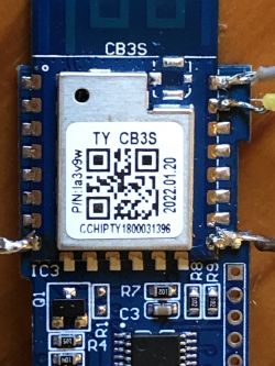
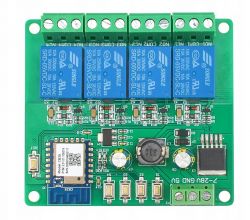
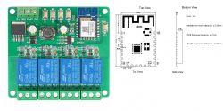
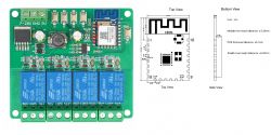
    I tried to run the Tuya module with four relays based on the CB3S WiFi system, after connecting the converter, programming using bk_writer went without any problems, I uploaded and ran the latest version of OpenBK7231N_QIO_1.14.104.bin. The soft started, I configured the WiFi but unfortunately I failed in the relay configuration, none of the saved templates worked, I ran 2, 3 and 4 logically, but e.g. the buttons on the board no longer worked, only "3" turned on the 4th relay correctly. Maybe someone has seen this board and can tell me how to configure it so that all relays work properly. Finally, I uploaded a backup of the original Tuya software and everything works, but unfortunately the Tuya local integration in HA is not satisfactory. :(

    Qiachip Smart Switch - BK7231N / CB2S - interior, programming
  • #194 20264353
    p.kaczmarek2
    Moderator Smart Home
    @kajarit uzupelniamy Readme

    @elo2 nie ma powodu by się poddawać. Przecież nawet na zdjęciu widać co jest co.
    Qiachip Smart Switch - BK7231N / CB2S - interior, programming
    Pin number Symbol I/O type Function
    1 RST I Low-level reset, high level active (the pin has been pulled high internally), correspond to CEN of the IC
    2 ADC3 AI ADC pin, which corresponds to P23 of the IC
    3 CEN I Enabling pin, which is pulled high internally to be compatible with other modules
    4 P14 I/O A common GPIO interface, which corresponds to P14 of the IC
    5 P26 I/O GPIOP_26, which corresponds to P26 of the IC, PWM 5
    6 P24 I/O GPIOP_24, which corresponds to P24 of the IC, PWM 4
    7 P6 I/O GPIOP_6, which corresponds to P6 of the IC, PWM 0
    8 VCC P Power supply pin (3.3V)
    9 GND P Power supply reference ground
    10 P9 I/O GPIOP_9, which corresponds to P9 of the IC, PWM 3
    11 TXD2 I/O UART2_TXD (used to display the module internal information), which corresponds to P0 of the IC
    12 CSN I/O Production test control pin. If it is used as a common I/O pin, it must be connected to the VCC externally. Do not connect it to the ground before the module is powered on.
    13 P8 I/O GPIOP_8, which corresponds to P8 of the IC, PWM 2
    14 P7 I/O GPIOP_7, which corresponds to P7 of the IC, PWM 1
    15 RXD1 I/O UART1_RXD (user serial interface), which corresponds to P10 of the IC. Do not connect it to the VCC. By default, the MCU serial port should be in low-level or high-impedance state.
    16 TXD1 I/O UART1_TXD (user serial interface), which corresponds to P11 of the IC. Do not connect it to the VCC. By default, the MCU serial port should be in low-level or high-impedance state.
    17 ADC3 AI (Not recommended. If needed, please use Pin 2) ADC port, which corresponds to P23 of the IC. Programmed SPI
    18 P22 I/O (Not recommended ) GPIOP_22, which corresponds to P22 of the IC. Programmed SPI
    19 CSN I/O The pull-up resistor is needed during usage of customers. Do not connect it to the ground before the module is powered on. Correspond to P21 of the IC.
    20 P20 I/O (Not recommended. ) GPIOP_20, which corresponds to P20 of the IC. Programmed SPI

    I can see where the paths are from here, I started to fill you in:
    Qiachip Smart Switch - BK7231N / CB2S - interior, programming
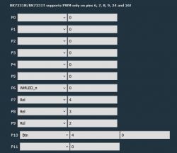
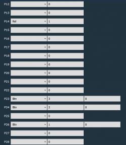
    It looks like ADC3, P26 and P24 are buttons, and e.g. P6 is an LED. You can also more or less see what goes to the relays... you can guess the rest... try it and let me know if I can help.
    PS: Where did you buy the CD?
    Helpful post? Buy me a coffee.
  • #195 20265559
    elo2
    Level 11  
    Hello,
    Thanks for the help, actually I figured it out yesterday, all I need to do is trace the paths, eventually the voltmeter and checking the states helped, the effect below is everything working.

    Qiachip Smart Switch - BK7231N / CB2S - interior, programming Qiachip Smart Switch - BK7231N / CB2S - interior, programming

    I have three such boards, two control the underfloor heating circuits and the third one controls the pumps, and the last one has already been converted and connected to the HA. All in all, the only thing missing is integration with HA, an app would be useful, as in the case of e.g. Tasmota, but after manually entering the configuration file it works beautifully, it was more fun with local tuya...
    Thank you for your help, in answer to your question, I ordered the tiles via Shopee from China for PLN 46 each.
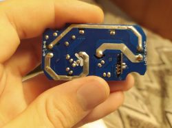
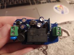
  • #196 20293493
    ionoleinic
    Level 10  
    Hi community, I am new to OpenBeken and i am using tasmota for my devices.I saw that many devices that arrived from aliexpress are with cb2s and cbu modules.and i found this topic and OpenBeken community.I am glad that people works together on these big projects as a alternative of tuya cloud firmaware, and i think that tasmota and OpenBeken should work together for a best result.
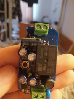
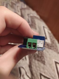
    So, i have a switch module like this https://www.elektroda.com/rtvforum/topic3874289.html based on cb2s module.My module is slightly different as pcb arangement. p.kaczmarek2 i saw that you connect power and ground to ams 1117 voltage regulator.I dont know where exactly i should connect 5V and ground on my pcb.
    Can i power cb2s module direct from usb UART module with 3.3V to cb2s pins and if not, why? i saw that somebody power through ams1117 regulator, somebody doesnt.
    And one more question about flashing cb2s module.Can i use BKwriter 1.60 for flashing OpenBK7231N_app_QIO_1.0.0.bin on cb2s module or i still use hid_download_py for this.
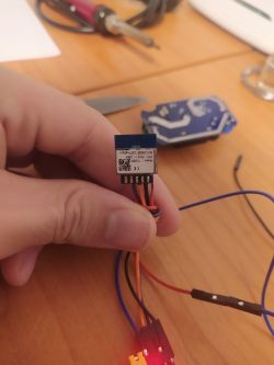
    Qiachip Smart Switch - BK7231N / CB2S - interior, programming Qiachip Smart Switch - BK7231N / CB2S - interior, programming Qiachip Smart Switch - BK7231N / CB2S - interior, programming Qiachip Smart Switch - BK7231N / CB2S - interior, programming
    Thank you very much!
    PS:Sorry for my english, I am from Moldova Republic of :))
  • #197 20293506
    p.kaczmarek2
    Moderator Smart Home
    Your English is very good, welcome to community, we are here to help.

    1. I do not recommend getting 3.3V directly from USB to UART because from my experience it is not reliable, those devices does not have current capability
    2. You can use IoT device onboard AMS1117 if one is on the board of your device. If not, then you have to use external one
    3. Never power device directly from mains while having UART connected!
    4. better use hid_download_py to flash N devices (and use QIO for N devices, offset 0)

    Depending on your soldering skills, the easiest approach for this device might be first desoldering whole CB2S, then soldering only 3.3V, GND, RX and TX and using 3.3V to do a reboot (just disconnect a power so device reboots), this is done while hid_download_py is waiting for "getting bus".

    The alternate option would be to use CEN for resetting, but this might be a bit more tricky.

    There are many approaches for that. We even have one video about similar device, but it is not translated yet - there are only subtitles.


    NOTE: the above video shows a bit more problematic case of relay - the case of relay with RX pin used for button, in that case one also has to cut the trace/remove capacitor from RX signal. Of course, there is always the "desolder whole CB2S" method as well, which I already mentioned in this post.

    In general, there are few different ways you can use to approach this.
    Helpful post? Buy me a coffee.
  • ADVERTISEMENT
  • #198 20293561
    ionoleinic
    Level 10  
    Thank you for reply.
    So, i should desolder module from pcb, flash it and solder back.Can i try to flash without desolder it? or it can be dangerous for module?
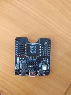
    I dont have another ams 1117 LOD regulator, but i have esp programmer. Qiachip Smart Switch - BK7231N / CB2S - interior, programming
    Can i use these pins to power cb2s module or it has low current too as USB to UART?
  • #199 20293589
    p.kaczmarek2
    Moderator Smart Home
    ionoleinic wrote:
    Thank you for reply.
    .Can i try to flash without desolder it? or it can be dangerous for module?

    I flash many times without desoldering and you can do this, but:
    1. You need to power to the module.
    METHOD 1: you need to find VIN of the LDO that is on the board and supply 5V here
    METHOD 2: supply 3.3V to CB2S directly
    2. You need to be able to RESET device in that configuration
    METHOD 1: you need to solder extra CEN wire and short CEN to GND to reset for 250ms (very tricky, I always have to attempt it 10 times before getting right)
    METHOD 2: you need to RESET/reboot device with disconnecting VDD wire from module (or from LDO) and keep USB to UART converter connected, but here comes the problem: if there is an electrolytic capacitor on board, it might take a large current when you connect wire, and it can overload your USB port . It will not damage the computer, your PC is safe, but it can temporary disconnect USB to UART dongle and cause programming to fail. This is why I used to desolder temporarily 220uF 16V caps (or similar) from devices...

    The important thing to know is that you have to RESET (either by power off/on or by CEN) after starting programming, while the programmer is trying to connect to BK.

    ionoleinic wrote:
    Qiachip Smart Switch - BK7231N / CB2S - interior, programming
    Can i use these pins to power cb2s module or it has low current too as USB to UART?

    I think they should be ok. I can see AMS1117.
    Helpful post? Buy me a coffee.
  • #200 20293707
    ionoleinic
    Level 10  
    Thank you, i will try also to save current firmware for guys from Tuya Cloudcutter.

    Added after 2 [hours] 19 [minutes]:

    I am getting this error when i am trying to read firmware
    cb2s reboots but want to read data from it.
    Qiachip Smart Switch - BK7231N / CB2S - interior, programming

    Added after 5 [minutes]:

    I tried with disconecting power and with CEN method.Same error.
    Qiachip Smart Switch - BK7231N / CB2S - interior, programming Qiachip Smart Switch - BK7231N / CB2S - interior, programming Qiachip Smart Switch - BK7231N / CB2S - interior, programming Qiachip Smart Switch - BK7231N / CB2S - interior, programming
  • #201 20294037
    p.kaczmarek2
    Moderator Smart Home
    Can you try bkWriter 1.60, at least for the reading?

    but it looks like "hid_download_py" should work. Maybe your device has button or a resistor or a capacitor connected to RX or TX pin, like the one in mentioned Youtube video?

    Dodano po 6 [minuty]:

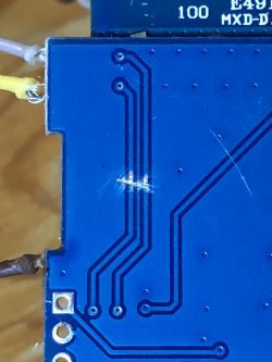
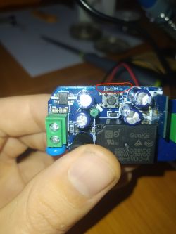
    Wait, what is this trace doing?
    Qiachip Smart Switch - BK7231N / CB2S - interior, programming
    Is it the RX pin trace? RX pin is used for something else?

    Don't you have the same issue like the one in our Youtube video?
    Helpful post? Buy me a coffee.
  • #202 20294125
    ionoleinic
    Level 10  
    OMG, there is a button :)
    Qiachip Smart Switch - BK7231N / CB2S - interior, programming Qiachip Smart Switch - BK7231N / CB2S - interior, programming [img-2]

    What should i do now? Desolder or cut trace? If i cut and not solder trace back button will not work, right?

    Added after 20 [minutes]:

    Qiachip Smart Switch - BK7231N / CB2S - interior, programming Qiachip Smart Switch - BK7231N / CB2S - interior, programming
    maybe rezistor is the problem and not button...
  • #203 20294186
    p.kaczmarek2
    Moderator Smart Home
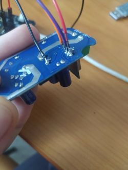
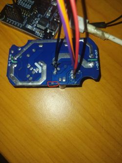
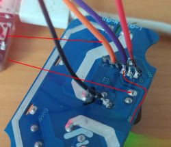
    Wait... does orange wire connects to the power supply capacitor pin?
    Qiachip Smart Switch - BK7231N / CB2S - interior, programming
    It is not clear from the photo, but maybe this module has different pinout? I am confused right now.

    Can you check that with a multimeter?
    Helpful post? Buy me a coffee.
  • #204 20294196
    ionoleinic
    Level 10  
    p.kaczmarek2 wrote:
    Wait... does orange wire connects to the power supply capacitor pin?
    Qiachip Smart Switch - BK7231N / CB2S - interior, programming
    It is not clear from the photo, but maybe this module has different pinout? I am confused right now.

    Can you check that with a multimeter?


    checked, there is ground connection of capacitor, it is not connected with rx or tx.
  • #205 20294204
    p.kaczmarek2
    Moderator Smart Home
    It is possible that this button has a pull down or up resistor that interferes with programming.
    You have two options:
    1. cut the trace and fix it later (just like on my Youtube video)
    2. choose the "desolder whole module" route, it's very easy with a flux and solder wick, and program module outside the board

    The method 2 is more reliable.
    Helpful post? Buy me a coffee.
  • #206 20296206
    ionoleinic
    Level 10  
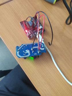
    Hi people, i flashed cb2s module with succes, but with my esp programers are hapennig strange things (I have 2 of them and both are doing same thing).I dont know if it should be that, but esp programer read from cb2s only and only if power 3.3V is not connected to cb2s and tx with rx are inversed (Tx -> Tx and Rx -> Rx).


    I didn't tried to flash with this method.

    Succesfuly flashed with USB to UART programmer.
    Qiachip Smart Switch - BK7231N / CB2S - interior, programming Qiachip Smart Switch - BK7231N / CB2S - interior, programming Qiachip Smart Switch - BK7231N / CB2S - interior, programming
    Qiachip Smart Switch - BK7231N / CB2S - interior, programming Qiachip Smart Switch - BK7231N / CB2S - interior, programming Qiachip Smart Switch - BK7231N / CB2S - interior, programming Qiachip Smart Switch - BK7231N / CB2S - interior, programming

    Thank you, p.kaczmarek2, for help.

    Added after 34 [minutes]:

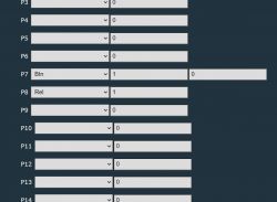
    My module has a different pinout configuration:
    P7: Btn
    P8: Rel
    P10: LED_n
  • #207 20297992
    jony4t
    Level 8  
    @p.kaczmarek2 At the end the bug that @00svd00 solved somehow for the BK731N. Has it been implemented in the new fixes? .thanks for your time
  • #208 20298791
    p.kaczmarek2
    Moderator Smart Home
    @ionoleinic very good job, it seems that in the end you've used my favourite method, and the simplest one, I'd bet (in this case simplest).

    @jony4t I have flashed multiple CB3S, CB2S and BK7231N devices and haven't managed to encounter this bug again. The only similar thing I found is that happens when you have two devices with the same MAC on network. Then the symptoms are the same, free memory goes down with each request until it's not able to even try to respond, because two devices with same MAC are fighting over the requests (at least in case of my router).
    Qiachip Smart Switch - BK7231N / CB2S - interior, programming
    Many improvements have been added in a meantime, but I am not sure if they fixed that particular case - I'd have to scroll back and find flash dump made at that time and check with new version.

    In general, LWIP should be way more stable now (no more crashes due to too many MQTT requests, or no more crashes after several days of using multiple drivers).

    And now we're addressing power save. It should be possible to run all devices in much more power saving mode than currently. Futhermore, it will be configurable so you'd be able to choose the option for you.
    Helpful post? Buy me a coffee.
  • #209 20299465
    jony4t
    Level 8  
    @p.kaczmarek2
    How Open beken has changed since August for the better. What a great job. Thanks for answering .
  • #210 20299612
    ionoleinic
    Level 10  
    @p.kaczmarek2 i saw that i can send mqtt commands like in tasmota (ex cmnd/qiachip/power on) but can't subscribe to stat/qiachip/power like in tasmota I can only subscribe only to "qiachip/1/get" but this type cause me many problems in the code.My project is based on mqtt communication, in it are involved some tasmota devices and this switch flashed with OpenBeken.Can you do this feature with 'stat/qiachip/power' like in tasmota?
    Thank you.

Topic summary

The discussion revolves around the Qiachip Smart Switch utilizing the BK7231N chip and the CB2S module, focusing on programming, firmware flashing, and integration with Home Assistant. Users share experiences with flashing the device using various tools like hid_download_py and uartprogram, troubleshooting issues such as connection problems, firmware compatibility, and device reboots. Key challenges include configuring WiFi settings, handling relay operations, and ensuring stable operation with different firmware versions. The community provides insights on soldering techniques, pin configurations, and the importance of power supply stability. Additionally, there are discussions about integrating DHT sensors and the need for improved firmware features.
Summary generated by the language model.
ADVERTISEMENT