Elektroda.com
Elektroda.com
X

Qiachip Smart Switch - BK7231N / CB2S - interior, programming

p.kaczmarek2 33771 266
This content has been translated flag-pl » flag-en View the original version here.
  • #151
    kajarit
    Level 6  
    Hello All,

    I have a temperature and humidity sensor with a CB3S module, which I'm trying to free from tuya cloud with your very promising BK7231N firmware. It works with 2 AA batteries. The article number is TW-TH002 I think.
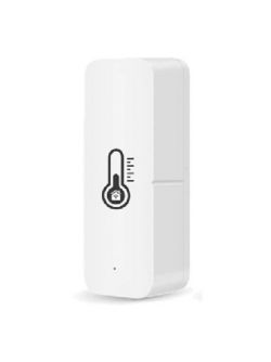
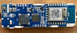
    Qiachip Smart Switch - BK7231N / CB2S - interior, programming
    Qiachip Smart Switch - BK7231N / CB2S - interior, programming

    I have a CH340G USB to TTL deivce for the task.
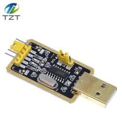
    Qiachip Smart Switch - BK7231N / CB2S - interior, programming

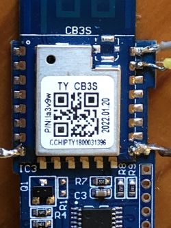
    I connected pins to the CB3S (8) VCC, (9) GND, (15) RX, (16) TX, and for resetting (3) CEN, and could download the firmware, but with CRC errors. TTL device is set to 3.3V.
    When I try to write the BK7231N (OpenBK7231N_QIO_1.12.48.bin) with -s 0x0, -u options, then I get an error right after start: "WriteSector 1 Failed"
    Do you have any idea how to continue?
  • #152
    p.kaczmarek2
    Moderator Smart Home
    What is the marking on the chip in SOIC?

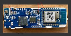
    I'd guess that's a TuyaMCU device. Most likely TuyaMCU has to be temporarily removed because it shared TX and RX lines with the lines that are used for programming.

    Second option would be to send 2MB flash dump to tuya-cloudcutter guys and wait for them to prepare OTA support for this device.

    Can you check with multimeter where the RX and TX of CB3S goes to? Is it connected to the MCU? Just to confirm...
  • #153
    kajarit
    Level 6  
    Could you clarify, I don't understand this:
    Quote:
    What is the marking on the chip in SOIC?


    Okay, I'll check next week as soon as I can, and get back to you.

    I could see a very similar device that you successfully flashed in post #100, did you cut the RX/TX connection to the MCU there?
  • #154
    p.kaczmarek2
    Moderator Smart Home
    kajarit wrote:
    Could you clarify, I don't understand this:
    Quote:
    What is the marking on the chip in SOIC?


    I am asking what is the chip name from the photo, because It's a bit blurry and it's hard for me to read.

    kajarit wrote:

    I could see a very similar device that you successfully flashed in post #100, did you cut the RX/TX connection to the MCU there?

    I had to cut RX/TX in order to flash, but it might be not necessary if you identify the chip and find if it has a reset pin in its datasheet.
    Here is more information about that device, sadly only in polish so far (use google translate):
    https://www.elektroda.pl/rtvforum/topic3914412.html
  • #155
    gowthaml
    Level 6  
    Hello All,
    I have smart switch with CB3S chip module, I am tried to establish connection with MQTT which I was hosted in remote server with Public IP and successfully connection establish with MQTT server while try to publish data to the device its started reboot without any error code's, I am tried multiple times publish data to device but its successfully subscribed to the server but starts reboot while receiving data..!!

    V:BK7231N_1.0.1
    REG:cpsr spsr r13 r14
    SVC:0000001F 00414570 0004C9F9
    IRQ:000000d2 0000003f 004037f0 000926e4
    FIR:000000d1 6000001f 00402800 00057bc8
    SYS:000000df 00414570 0004c9f9
    ST:00000000
    J 0x10000
    bk_misc_init_start_type a 0
    prvHeapInit-start addr:0x40dd90, size:139888
    [Flash]id:0x1c7015
    sctrl_sta_ps_init
    xat0_reboot


    V:BK7231N_1.0.1
    REG:cpsr spsr r13 r14
    SVC:000000D3 00401C1C 000033AC
    IRQ:000000d2 00000010 00401e0c 00005320
    FIR:000000d1 00000010 00401ffc 00057bc8
    SYS:000000df 0040192c 00000158
    ST:0001AD05
    J 0x10000
    bk_misc_init_start_type 5 1ad05
    prvHeapInit-start addr:0x40dd90, size:139888
    [Flash]id:0x1c7015
    sctrl_sta_ps_init
    cset:0 0 0 0
    bandgap_calm_in_efuse=0x62
    [load]bandgap_calm=0x62->0x22,vddig=4->5
    [FUNC]rwnxl_init
    [bk]tx_txdesc_flush
    [FUNC]intc_init
    [FUNC]calibration_main
    gpio_level=1,txpwr_state=15
    user define rfcali mode:1
    get rfcali_mode:1

    calibration_main over
    flash txpwr table:0xf
    dif g and n20 ID in flash:4
    dif g and n40 ID in flash:4
    read txpwr tab from flash success
    temp in flash is:358
    xtal in flash is:66
    xtal_cali:66
    --init_xtal = 66
    [FUNC]ps_init
    [FUNC]func_init_extended OVER!!!

    start_type:5
    Version:
    Initializing TCP/IP stack
    tcp_port:62642
    app_init finished

    Periodic reboot t[sa_sta]MM_RESET_REQ
    [bk]tx_txdesc_flush
    a
    [sa_sta]ME_CONFIG_REQ
    [sa_sta]ME_CHAN_CONFIG_REQ
    [sa_sta]MM_START_REQ
    ht in scan
    scan_start_req_handler
  • #157
    gowthaml
    Level 6  
    p.kaczmarek2 wrote:
    Hello, have you tried fixed 2MB binary from this post?
    https://www.elektroda.com/rtvforum/viewtopic.php?p=20148034#20148034


    No, I am just followed "https://www.elektroda.com/rtvforum/topic3874289.html" this post and tried to connect with MQTT and successfully connected with if data tried to received device reboots..!!!

    As you said from above reply if I removed garbages values by flashing 2MB firmware, you said to backup Mac address and how can i backup MAC address?
  • #158
    kajarit
    Level 6  
    p.kaczmarek2 wrote:
    kajarit wrote:
    Could you clarify, I don't understand this:
    Quote:
    What is the marking on the chip in SOIC?


    I am asking what is the chip name from the photo, because It's a bit blurry and it's hard for me to read.


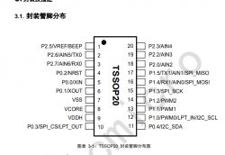
    I couldn't make a better picture, but I think this is an Unicmicro UM8005-ACTE (TSSOP20) microcontroller.
  • #159
    p.kaczmarek2
    Moderator Smart Home
    gowthaml wrote:

    As you said from above reply if I removed garbages values by flashing 2MB firmware, you said to backup Mac address and how can i backup MAC address?

    just change MAC to anything you want after doing the flashing, you can change MAC in obk settings

    kajarit wrote:
    p.kaczmarek2 wrote:
    kajarit wrote:
    Could you clarify, I don't understand this:
    Quote:
    What is the marking on the chip in SOIC?


    I am asking what is the chip name from the photo, because It's a bit blurry and it's hard for me to read.


    I couldn't make a better picture, but I think this is an Unicmicro UM8005-ACTE (TSSOP20) microcontroller.

    Qiachip Smart Switch - BK7231N / CB2S - interior, programming
    I didn't have time to read whole datasheet, but you can find one on the web, and it seems there is a RST pin. Maybe connecting this pin to ground or something will put chip in RESET mode and allow you to read and write flash from UART with no interference.
    Otherwise you will have to cut the tracks... the UART used to talk with this chip is the same as programming UART
  • #160
    gowthaml
    Level 6  
    p.kaczmarek2 wrote:

    just change MAC to anything you want after doing the flashing, you can change MAC in obk settings


    As you said flashed full firmware bin file to remove garbage values from flash and after removing all again flashed firmware and start trying to connect with MQTT but this time MQTT while trying to subscribe topic its starts reboot..!!


    MQTT client "cbs" connection cb: status 0

    MQTT client "cbs" request cb: err 0
    MQTT client "cþ
    V:BK7231N_1.0.1
    REG:cpsr spsr r13 r14
    SVC:0000001F 00414570 0004C9F9
    IRQ:000000d2 0000003f 004037f0 0004c524
    FIR:000000d1 6000001f 00402800 00057bc8
    SYS:000000df 00414570 0004c9f9
    ST:00000000
    J 0x10000
    bk_misc_init_start_type a 0
    prvHeapInit-start addr:0x40dd90, size:139888
    [Flash]id:0x1c7015
    sctrl_sta_ps_init
    xat0_reboot

    [13:52:22.004]IN¡û¡Ã´
    V:BK7231N_1.0.1
    REG:cpsr spsr r13 r14
    SVC:000000D3 00401C1C 000033AC
    IRQ:000000d2 00000010 00401e0c 00005364
    FIR:000000d1 00000010 00401ffc 00057bc8
    SYS:000000df 0040192c 00000158
    ST:0001AD05
    J 0x10000
    bk_misc_init_start_type 5 1ad05
    prvHeapInit-start addr:0x40dd90, size:139888
    [Flash]id:0x1c7015
    sctrl_sta_ps_init
    cset:0 0 0 0
    bandgap_calm_in_efuse=0x62
    [load]bandgap_calm=0x62->0x22,vddig=4->5
    [FUNC]rwnxl_init
    [bk]tx_txdesc_flush
    [FUNC]intc_init
    [FUNC]calibration_main
    gpio_level=1,txpwr_state=0
    user define rfcali mode:1
    get rfcali_mode:1

    [13:52:22.488]IN¡û¡Ã´calibration_main over
    NO TXPWR_TAB_TAB found in flash
    Load default txpwr for b:0x95844
    Load default txpwr for g:0x95852
    fit n20 table with dist:4
    Load default txpwr for n40:0x95860
    Load default txpwr for ble:0x966d9
    temp in flash is:350
    xtal in flash is:12
    xtal_cali:12
    --init_xtal = 12
    [FUNC]ps_init
    [FUNC]func_init_extended OVER!!!
  • #161
    p.kaczmarek2
    Moderator Smart Home
    Are you saying that it reboots even after @00svd00 fix?

    Ok, can you check the very same version that I have running for 18 days already?
    Qiachip Smart Switch - BK7231N / CB2S - interior, programming
    This version: Build on Aug 22 2022 23:03:50 version 1.12.41 pick that one from releases and check.
  • #162
    gowthaml
    Level 6  
    Yes, as you said I reflashed 2MB firmware and tested still reboots on subscribing topic. If not subscribed its connecting to MQTT server and can able to publish data. I am just trying to implement own MQTT connection establishment from this below example post https://www.elektroda.com/rtvforum/topic3850712.html
    I am trying your example own MQTT connection from above post and not trying to use home assistance or Tasmota.
  • #163
    p.kaczmarek2
    Moderator Smart Home
    Wait wait wait, are you saying that you're not using OpenBeken?
    You are linking to the old non-OBK tutorial of mine...
    Can you confirm, are you using OpenBeken or are you trying to write your own code?
    Can you show me your code?
  • #165
    p.kaczmarek2
    Moderator Smart Home
    gowthaml wrote:
    Yes, I am using own code to connect with server and using your example reference code from below topic
    https://www.elektroda.com/rtvforum/topic3850712.html

    Oh c'mon, you really got me worried, everyone thought you're talking about OpenBeken.

    Ok, now, I know this issue. I and @btsimonh has most likely experienced the same.
    I don't remember the fix from the top of my head, but here are 3 hints:
    1. don't start WiFi just after rebooting device, wait a 5 or so seconds (it's already in obk)
    2. don't start MQTT immediately, start it when WiFi reports a successful connection, maybe with extra delay
    3. do not do MQTT calls within MQTT callbacks - or something like that...
    4. the best now you can do is to look back at the history of my OBK drafts, maybe attachment from first post:
    https://www.elektroda.com/rtvforum/topic3866123.html
    or maybe in obk history itself:
    https://github.com/openshwprojects/OpenBK7231...h=master&qualified_name=refs%2Fheads%2Fmaster
    https://github.com/openshwprojects/OpenBK7231...d38dc670/apps/my_alpha_demo/src/tuya_device.c
  • #166
    gowthaml
    Level 6  
    Thank You so much sir, Its worked fine by adding some delay and mqtt callback in proper way solved the issues. :D
    Do you have any proper way of storing wifi cred into flash and read from flash ?
  • #167
    p.kaczmarek2
    Moderator Smart Home
    Here are my functions used to access flash memory on BK7231 platform:
    https://github.com/openshwprojects/OpenBK7231.../main/src/hal/bk7231/hal_flashConfig_bk7231.c
    Here is the abstract config that is shared between all platforms:
    https://github.com/openshwprojects/OpenBK7231T_App/blob/main/src/new_cfg.c
    Here is the Tuya method (or maybe Beken?) of saving data to flash (I used it in the past):
    https://github.com/openshwprojects/OpenBK7231..._os/beken378/func/user_driver/BkDriverFlash.c
  • #168
    kajarit
    Level 6  
    p.kaczmarek2 wrote:
    I didn't have time to read whole datasheet, but you can find one on the web, and it seems there is a RST pin. Maybe connecting this pin to ground or something will put chip in RESET mode and allow you to read and write flash from UART with no interference.
    Otherwise you will have to cut the tracks... the UART used to talk with this chip is the same as programming UART


    I couldn't achieve better results by trying to connect GND to Unicmicro UM8005-ACTE (TSSOP20) microcontroller's RST - which I think is pin 4: P0.2/NRST.
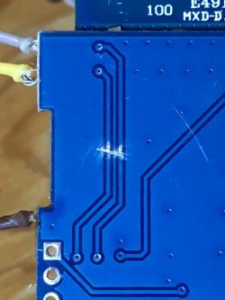
    So I cut the tracks to RX, TX on the back, checked with multimeter, definitely not connected anymore.
    However I still get CRC check failed at the end of backup.
    Any idea?
  • #169
    p.kaczmarek2
    Moderator Smart Home
    CRC error is normal in case of this flashing tool and can be ignored. There is nothing to worry about.

    If all sectors were read, and you have a 2MB file, then it's ok already.

    When in doubt, just do a backup twice.
  • #170
    kajarit
    Level 6  
    p.kaczmarek2 wrote:
    CRC error is normal in case of this flashing tool and can be ignored. There is nothing to worry about.

    If all sectors were read, and you have a 2MB file, then it's ok already.

    When in doubt, just do a backup twice.


    Okay, I thought this CRC check is working.

    Sure I think so, the file size is 2097152 bytes.

    Actually I made 4 files with the following settings, which one is the best? :)
    1. -l 0x200000 -b 115200
    2. -s 0x0 -l 0x200000 -b 115200
    3. -l 0x200000 -u -b 115200
    4. -s 0x0 -l 0x200000 -u -b 115200

    Added after 41 [minutes]:

    I tried to upload the firmware file OpenBK7231N_QIO_1.12.55.bin (options -s 0x0 -u), but after getting the bus, it stops with the below error:
    Code: text
    Log in, to see the code


    Also if I didn't set -b 115200, then it stops with:
    Code: text
    Log in, to see the code
  • #171
    p.kaczmarek2
    Moderator Smart Home
    This is the one I use and it's proven that it works (but -u is a shorthand for --unprotect):
    
    python uartprogram LastBuild.bin --unprotect -d com10 -w --startaddr 0x0
    pause


    kajarit wrote:


    I tried to upload the firmware file OpenBK7231N_QIO_1.12.55.bin (options -s 0x0 -u), but after getting the bus, it stops with the below error:
    Code: text
    Log in, to see the code


    Also if I didn't set -b 115200, then it stops with:
    Code: text
    Log in, to see the code


    Anyway, are we talking about the same device you have already programmed before?
    Regarding the problems, I need to have more information. There can be multiple reasons for such error. Can you show a photo of your setup?
    1. Was it working earlier? I am not sure as it sounded you are already flashing it correctly and now you report errors.... is it the same device?
    2. Do you have anything also connected on RX/TX lines? There are some devices that have, for example, a debouncing capacitor on RX line (I've had such relay once) that needs to be removed before flashing. Some other devices might use RX/TX lines to communicate with TuyaMCU chip, which also makes flashing a bit more problematic, because you have to remove TuyaMCU or cut the lines first (or put the MCU In reset state)
    3. How do you reset the WiFi module, by CEN or by power on/off cycle? Doing a reset is tricky, it takes several times to get it right.

    BTW: If you have successfully done a firmware backup, you can submit it here:
    https://github.com/tuya-cloudcutter/tuya-cloudcutter/issues

    EDIT: Or are you trying to say that flashing your own build worked, but flashing OBK does not?
  • #172
    kajarit
    Level 6  
    p.kaczmarek2 wrote:


    Anyway, are we talking about the same device you have already programmed before?
    Regarding the problems, I need to have more information. There can be multiple reasons for such error. Can you show a photo of your setup?
    1. Was it working earlier? I am not sure as it sounded you are already flashing it correctly and now you report errors.... is it the same device?
    2. Do you have anything also connected on RX/TX lines? There are some devices that have, for example, a debouncing capacitor on RX line (I've had such relay once) that needs to be removed before flashing. Some other devices might use RX/TX lines to communicate with TuyaMCU chip, which also makes flashing a bit more problematic, because you have to remove TuyaMCU or cut the lines first (or put the MCU In reset state)
    3. How do you reset the WiFi module, by CEN or by power on/off cycle? Doing a reset is tricky, it takes several times to get it right.


    We're talking about the same thermometer (and humidity) device, which I try to flash with your bin, couldn't flash it yet.

    1. Nope, I wrote this in my first post:
    Quote:
    When I try to write the BK7231N (OpenBK7231N_QIO_1.12.48.bin) with -s 0x0, -u options, then I get an error right after start: "WriteSector 1 Failed"


    2. Only the MCU was, I've cut the lines as the MCU RST pin grounding didn't do the trick for me.
    Quote:
    I couldn't achieve better results by trying to connect GND to Unicmicro UM8005-ACTE (TSSOP20) microcontroller's RST - which I think is pin 4: P0.2/NRST.
    So I cut the tracks to RX, TX on the back, checked with multimeter, definitely not connected anymore.


    3. By connecting CEN to ground, as I mentioned before. This is working as it starts the backup process also (until I don't ground it, it waits).
    Quote:
    I connected pins to the CB3S (8) VCC, (9) GND, (15) RX, (16) TX, and for resetting (3) CEN
  • #173
    p.kaczmarek2
    Moderator Smart Home
    Ah ok @kajarit , I mistaken your post with @gowthaml

    So you were never able to flash any binary to this device yet, right? Not even reflash back the backup of the firmware? But you can READ correctly the flash?

    Is your power connect directly to CB3S? 3.3V to 3.3V of CB3S? I am asking because this board has a transistor and TuyaMCU by default turns off the WiFI module after some time.
    Or maybe is your 3.3V connected to the battery connector? If so, it's a wrong approach, because TuyaMCU can disconnect that.
    Qiachip Smart Switch - BK7231N / CB2S - interior, programming

    Other than that, I am running out of ideas. Take a look here:
    https://www.elektroda.pl/rtvforum/topic3914412.html
    it might not be yet translated (use Google Translate) but I have easily flashed both such boards as in linked topic by cutting RX/TX traces and powering the WiFi module directly (to the 3.3V pin of CB3S)


    Maybe your UART to USB converter has not enough current capability? Can you show photos? Have you tried powering it from external LDO 3.3V?
  • #174
    kajarit
    Level 6  
    p.kaczmarek2 wrote:
    Is your power connect directly to CB3S? 3.3V to 3.3V of CB3S? I am asking because this board has a transistor and TuyaMCU by default turns off the WiFI module after some time.
    Or maybe is your 3.3V connected to the battery connector? If so, it's a wrong approach, because TuyaMCU can disconnect that.


    I've soldered wires directly to each pin on the CB3S, I'll provide photos later, when I get home.

    Added after 3 [minutes]:

    p.kaczmarek2 wrote:
    Maybe your UART to USB converter has not enough current capability? Can you show photos? Have you tried powering it from external LDO 3.3V?


    I'm using a "golden standard" :) USB to TTL dongle, as recommended "officially" for Tasmota. However I don't know how to check that for sure.

    Quote:
    Many CH340G devices will not work, the "golden CH340G" has a voltage regulator on it to supply enough power to the ESP device - many do not. The ESP requires at least 150mA, many 3.3V serial programmers do not supply this much current as many serial programming tasks do not require a large amount of power.
  • #175
    p.kaczmarek2
    Moderator Smart Home
    If you're using CEN for resetting, what about putting in the device two AAA batteries and then doing a temporary short around the power control MOSFET?
    This way you will power the CB3S from batteries and not from USB to UART converter. Also, of course, disconnect the USB to UART converter from VCC in this case.

    I have a slight feeling that I remember sometime ago having issue with writing but being able to read, and it was because of write operation requiring slightly more current, but maybe I am wrong.
  • #176
    kajarit
    Level 6  
    p.kaczmarek2 wrote:
    Ah ok @kajarit , I mistaken your post with @gowthaml
    Maybe your UART to USB converter has not enough current capability? Can you show photos? Have you tried powering it from external LDO 3.3V?


    Powering it through the "golden" CH340G which is - in theory - able to provide 150mA according to specs.

    Qiachip Smart Switch - BK7231N / CB2S - interior, programming Qiachip Smart Switch - BK7231N / CB2S - interior, programming
  • #177
    gowthaml
    Level 6  
    Hello All,
    Have any one ported mdns application for cb2s from lwip? If yes , then how can I enable mdns and use mdns?
  • #178
    p.kaczmarek2
    Moderator Smart Home
    @gowthaml why do you need that? I might look into it.

    IMPORTANT UPDATE
    The N platform instability has been fixed (or at least seriously improved).
    The LWIP version has been updated.
    The N platform should not crash anymore, at least because of LWIP.

    This addresses the issues discussed earlier in this thread.
  • #179
    gowthaml
    Level 6  
    I am using my own Wi-Fi credentials method and I need mDNS to resolve ip addresses of the device .
  • #180
    omelchuk890
    Level 10  
    I bought some more switches.
    I immediately got caught on the BK7231N ...
    The body of the product is like the previous ones, but those were on T.
    I'm thinking how to connect?
    Soldering everyone is stressful. I'll try to make a needle connector for the points on the board.


    After a while, at 18.16
    The board was stitched using soldering and the command line. the most recent at the moment OpenBK7231N_QIO_1.12.103.bin.
    It was an interesting shamanism, my hand hurts from the tambourine ...
    I will try, if the Author of the topic does not mind, tomorrow I will write a detailed, step-by-step, guide for the BK7231N firmware from under Windows using the example of W7.
    Sorry, I'm writing through a translator